Advertisement
Quick Links
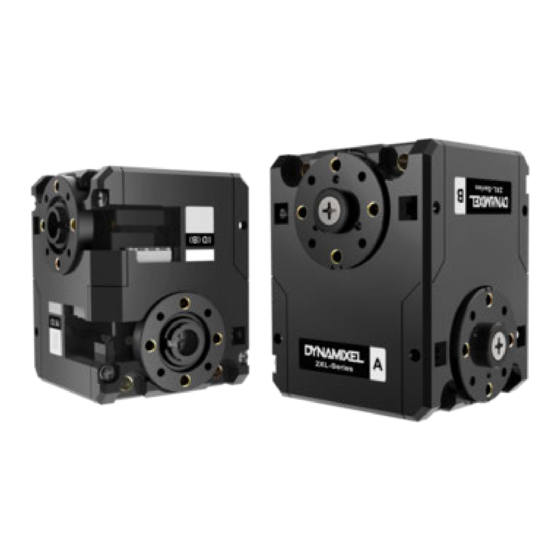
2XL430-W250
1. Specifications
2XL430-W250 is a ground breaking DYNAMIXEL that allows to control 2 axis(2 DOF) with a single
module. In order to control 2 axis at the same time, each axle should be assigned with different ID
while sharing an identical Baudrate. Since the Control Table for each axle is separated except the
Baudrate, 2XL can be applied in various applications.
The usage is identical to other DYNAMIXEL's, but be aware that Firmware Recovery will reset both
axis to factory settings.
Item
MCU
Position Sensor
Motor
Baud Rate
Control Algorithm
Resolution
Operating Modes
Weight
Dimensions (W x H x D)
Gear Ratio
Stall Torque
Specifications
ARM CORTEX-M3 (72 [MHz], 32Bit)
Contactless absolute encoder (12Bit, 360 [°])
Maker : ams(www.ams.com), Part No : AS5601
Cored
9,600 [bps] ~ 4.5 [Mbps]
PID control
4096 [pulse/rev]
Velcoity Control Mode
Position Control Mode (0 ~ 360 [°])
Extended Position Control Mode (Multi-turn)
PWM Control Mode (Voltage Control Mode)
98.2 [g]
36 x 46.5 x 36 [mm]
257.4 : 1
1.0 [N.m] (at 9.0 [V], 1.0 [A])
1.4 [N.m] (at 11.1 [V], 1.3 [A])
1.5 [N.m] (at 12.0 [V], 1.4 [A])
Advertisement

Related Manuals for Robotis 2XL430-W250


Summary of Contents for Robotis 2XL430-W250
- Page 1 2XL430-W250 1. Specifications 2XL430-W250 is a ground breaking DYNAMIXEL that allows to control 2 axis(2 DOF) with a single module. In order to control 2 axis at the same time, each axle should be assigned with different ID while sharing an identical Baudrate. Since the Control Table for each axle is separated except the Baudrate, 2XL can be applied in various applications.
- Page 2 Item Specifications 47 [rev/min] (at 9.0 [V]) No Load Speed 57 [rev/min] (at 11.1 [V]) 61 [rev/min] (at 12.0 [V]) Operating Temperature -5 ~ +72 [°C] Input Voltage 6.5 ~ 12.0 [V] (Recommended : 11.1 [V]) Command Signal Digital Packet TTL Half Duplex Asynchronous Serial Communication Protocol Type (8bit, 1stop, No Parity)
-
Page 3: Control Table
Generally, Max Torque of the Performance Graph is less than the Stall Torque. CAUTION : When supplying power It is recommended using ROBOTIS controller or SMPS2DYNAMIXEL. Do not connect or disconnect DYNAMIXEL when power is being supplied. 2. Control Table The Control Table is a structure of data implemented in the device. - Page 4 unique value when accessing a specific Data in the Control Table with Instruction Packets. In order to read or write data, users must designate a specific Address in the Instruction Packet. Please refer to Protocol 2.0 for more details about Instruction Packets. NOTE : Two’s complement is applied for the negative value.
- Page 5 Size Default Address Data Name Access Range Unit (Byte) Value Baud Rate 0 ~ 7 Return Delay Time 0 ~ 254 2 [μsec] Drive Mode 0 ~ 1 Operating Mode 0 ~ 16 Secondary(Shadow) ID 0 ~ 252 Protocol Type 1 ~ 2 -1,044,479 ~ Homing Offset...
- Page 6 Size Default Address Data Name Access Range Unit (Byte) Value Feedforward 1st Gain 0 ~ 16,383 Bus Watchdog 1 ~ 127 20 [msec] -PWM Limit(36) ~ Goal PWM PWM Limit(36) -Velocity Limit(44) ~ Goal Velocity 0.229 [rev/min] Velocity Limit(44) 0 ~ 32,767 214.577 [rev/min Profile Acceleration 0 ~ 32,737...
- Page 7 Size Default Address Data Name Access Range Unit (Byte) Value … … … … … Indirect Data 26 0 ~ 255 Indirect Data 27 0 ~ 255 Indirect Data 28 0 ~ 255 Indirect Address 29 64 ~ 661 Indirect Address 30 64 ~ 661 Indirect Address 31 64 ~ 661...
- Page 8 2. 4. 2. Firmware Version(6) This address stores firmware version of DYNAMIXEL. 2. 4. 3. ID(7) The ID is a unique value in the network to identify each DYNAMIXEL with an Instruction Packet. 0~252 (0xFC) values can be used as an ID, and 254(0xFE) is occupied as a broadcast ID.
- Page 9 2. 4. 5. Return Delay Time(9) After the DYNAMIXEL receives an Instruction Packet, it delays transmitting the Status Packet for Return Delay Time(9). For instance, if the Return Delay Time(9) is set to ‘10’, the Status Packet will be returned after 20[μsec] when the Instruction Packet is received. Unit Value Range Description...
- Page 10 Operating Value Description Mode This mode controls position and identical to the Joint Mode. Operating position range is limited by Max Position Limit(48) and Min Position 3(Default) Position Limit(52). Control Mode This mode is ideal for articulated robots that each joint rotates less than 360°.
- Page 11 Set the DYNAMIXEL’s Secondary ID. Secondary ID(12) is a value to identify each DYNAMIXEL, just like the ID(7). However, unlike ID(7), Secondary ID(12) is not a unique value. Therefore, DYNAMIXEL with the same Secondary ID value form a group. The differences between Secondary ID(12) and ID(7) are as follows : 1.
- Page 12 WARNING : In order to change the Protocol Type to Protocol 1.0, please use DYNAMIXEL Wizard 2.0 as R+ Manager 2.0 does not support Protocol 1.0. NOTE : The protocol 2.0 is greatly enhanced from the protocol 1.0. Accessing some of the Control Table area might be denied if protocol 1.0 is selected.
- Page 13 This value limits operating temperature. When the Present Temperature(146) that indicates internal temperature of DYNAMIXEL is greater than the Temperature Limit(31), the Over Heating Error Bit(0x04) and Hardware Error Bit(0x80) in the Hardware Error Status(70) will be set. If Overheating Error Bit(0x04) is configured in the Shutdown(63), Torque Enable(64) cleared to ‘0’...
- Page 14 NOTE: The default value of Velocity Limit(44) has been decreased since Firmware V42. 2. 4. 16. Min/Max Position Limit(48, 52) These values limit maximum and minimum desired positions for Position Control Mode(Joint Mode) within the range of 1 rotation(0 ~ 4,095). Therefore, Goal Position(116) should be configured within the position limit range.
- Page 15 Item Description Detect internal temperature exceeds the configured operating OverHeating Error(default) temperature Unused, Always ‘0’ Input Voltage Error Detect input voltage exceeds the configured operating voltage NOTE : 1. If Shutdown occurs, LED will flicker every second. (Firmware v41 or above) 2.
- Page 16 2. 4. 20. Status Return Level(68) This value decides how to return Status Packet when DYNAMIXEL receives an Instruction Packet. Value Responding Instructions Description PING Instruction Status Packet will not be returned for all Instructions PING Instruction Status Packet will be returned only for READ Instruction READ Instruction All Instructions Status Packet will be returned for all Instructions...
- Page 17 Item Description Unused, Always ‘0’ Overload Error(default) Detect persistent load that exceeds maximum output Electrical Shock Detect electric shock on the circuit or insufficient power to operate the Error(default) motor Motor Encoder Error Detect malfunction of the motor encoder Detect internal temperature exceeds the configured operating OverHeating Error(default) temperature Unused, Always ‘0’...
- Page 18 Goal Velocity(104) is converted to desired velocity trajectory by Profile Acceleration(108). 3. The desired velocity trajectory is stored at Velocity Trajectory(136). 4. PI controller calculates PWM output for the motor based on the desired velocity trajectory. Goal PWM(100) sets a limit on the calculated PWM output and decides the final PWM value.
- Page 19 Controller Conversion Range Description Gain Equations Feedforward 1st Feedforward Velocity Gain FF1st FF1st(TBL) Gain(90) 16,383 Below figure is a block diagram describing the position controller in Position Control Mode and Extended Position Control Mode. When the instruction from the user is received by DYNAMIXEL, it takes following steps until driving the horn.
- Page 20 Bus Watchdog (98) is available from firmware v38. It is a safety device (Fail-safe) that stops the DYNAMIXEL if the communication between the controller and DYNAMIXEL communication (RS485, TTL) is disconnected due to an unspecified error. Communication is defined as all the Instruction Packet in the DYNAMIXEL Protocol. Values Description Unit...
- Page 21 In case of PWM Control Mode, both PID controller and Feedforward controller are deactivated while Goal PWM(100) value is directly controlling the motor through an Inverter. In other control modes, this value is used to limit PWM value. This value cannot exceed Limit(36).
- Page 22 Time-based Values Description Profile ‘0’ stands for an infinite accelerating time(‘0 [msec]’). Range Profile Acceleration(108) will not exceed 50% of Profile Velocity(112) 32737 value. NOTE : Time-based Profile is available from the firmware version 42. 2. 4. 29. Profile Velocity(112) If Velocity-based Profile is selected for Drive Mode(10),...
- Page 23 When given Goal Position(116), DYNAMIXEL’s profile creates desired velocity trajectory based on present velocity(initial velocity of the Profile). When DYNAMIXEL receives updated desired position from a new Goal Position(116) while it is moving toward the previous Goal Position(116), velocity smoothly varies for the new desired velocity trajectory.
- Page 24 NOTE : Velocity Control Mode only uses Profile Acceleration(108). Step and Trapezoidal Profiles are supported. Velocity Override are supported as well. Acceleration time(t1) can be calculated as below equation. Velocity-based Profile : t = 64 * {Goal Velocity(104) Profile Acceleration(108)} Time-based Profile : t Profile Acceleration(108) NOTE : If Time-based Profile is selected,...
- Page 25 Mode Values Description Min Position Limit(52) ~ Max Position Initial Value : 0 ~ Position Control Mode Limit(48) 4,095 Extended Position Control -1,048,575 ~ 1,048,575 -256[rev] ~ 256[rev] Mode Degree Conversion Constant Description 0.088°/Value 1[rev] : 0 ~ 4,095 NOTE : Profile Velocity(112) and Profile Acceleration(108) are applied in below cases: In Position Control Mode, Profile Velocity(112) and...
- Page 26 Unit Value Range Description 1 ms 0 ~ 32,767 The value resets to ‘0’ when it exceeds 32,767 2. 4. 32. Moving(122) This value indicates whether DYNAMIXEL is in motion or not. If absolute value of Present Velocity(128) is greater than Moving Threshold(24), Moving(122) is set to ‘1’.
- Page 27 NOTE : In-Position bit will be set when the positional deviation is smaller than a predefined value under Position related control modes. 2. 4. 34. Present PWM(124) This value indicates current PWM. For more details, please refer to the Goal PWM(100).
- Page 28 1. Velocity Control Mode : When Profile reaches to the endpoint, Velocity Trajectory(136) becomes equal to Goal Velocity(104). 2. Position Control Mode, Extended Position Control Mode : Velocity Trajectory is used to create Position Trajectory(140). When Profile reaches to an endpoint, Velocity Trajectory(136) is cleared to ‘0’.
-
Page 29: How To Assemble
4. Indirect Address 5(176) : change the value to ‘119’ which is the fourth address of Goal Position. 5. Set 4 byte value ‘1,024’ to Indirect Data 2 : Goal Position(116) also becomes ‘1024’ and DYNAMIXEL moves. Indirect Address Range Description 64 ~ 661 EEPROM address can’t be assigned to Indirect Address... - Page 30 CAUTION : DYNAMIXEL X-Series cable assembly through hollow case Organize the entangled cable before assembling the back case. Do not assemble the back case with entangled cable. The entangled cable can be squashed by the case and cause communication error. Do not assemble both cables through the hollow case.
- Page 31 4. Reference NOTE Compatibility Guide Harness Compatibility 4. 1. Certifications Please inquire us for information regarding unlisted certifications. 4. 1. 1. FCC Note: This equipment has been tested and found to comply with the limits for a Class B digital device, pursuant to part 15 of the FCC Rules.
- Page 32 4. 3. Connector Information Item Pinout DATA Diagram Housing JST EHR-03 PCB Header JST B3B-EH-A Crimp Terminal JST SEH-001T-P0.6 Wire Gauge 21 AWG WARNING: Check the pinout! The pinout of DYNAMIXEL can differ from the pinout of connector manufacturer. 4. 4. Communication Circuit To control the DYNAMIXEL actuators, the main controller needs to convert its UART signals to the half duplex type.
- Page 33 WARNING: Check the pinout! The pinout of DYNAMIXEL can differ from the pinout of connector manufacturer. 4 . 5. Drawings 2XL430.pdf Download 2XL430.dwg Download 2XL430.stp Download ROBOTIS Download Center Please also checkout for software applications, 3D/2D CAD, and other useful resources! © 2020 ROBOTIS. Powered by Jekyll & Minimal Mistakes. www.pishrobot.com...
Need help?
Do you have a question about the 2XL430-W250 and is the answer not in the manual?
Questions and answers