Advertisement
Quick Links
2/22/2018
Show
ROBOTIS e-Manual v1.31.30
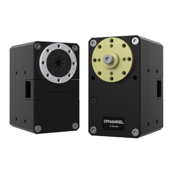
XM540-W150-T / XM540-W150-R
Part Photo
H/W Specifications
MCU : ST CORTEX-M3 ( STM32F103C8 @ 72MHZ,32BIT)
POSITION SENSOR : Contactless absolute encoder (12BIT, 360°)
Motor : Coreless
Baud Rate : 9600 bps ~ 4.5 Mbps
Control Algorithm : PID CONTROL
Degree of Precision : 0.088°
Operating Modes
Current Control Mode
Velocity Control Mode
Position Control Mode (0° ~ 360°)
Extended Position Control Mode (Multi-turn)
Current-based Position Control Mode
PWM Control Mode
Weight : 165g
Dimensions(W x H x D) : 33.5mm x 58.5mm x 44mm
Gear Ratio : 152.3 : 1
Stall Torque
6.9N.m (at 11.1V, 4.2A)
7.3N.m (at 12.0V, 4.4A)
8.9N.m (at 14.8V, 5.5A)
No load speed
50rpm (at 11.1V)
53rpm (at 12.0V)
66rpm (at 14.8V)
Operating Temperature : -5℃ ~ +80℃
Input Voltage : 10 ~ 14.8V (Recommended : 12V)
Command Signal : Digital Packet
Protocol Type
XM540-W150-T (Half duplex Asynchronous Serial Communication (8bit, 1stop, No Parity)
XM540-W150-R (RS485 Asynchronous Serial Communication (8bit, 1stop, No Parity)
Link (Physical)
XM540-W150-T (TTL Level Multi Drop Bus)
XM540-W150-R (RS485 Multi Drop Bus)
ID : 253 ID (0~252)
Feedback : Position, Velocity, Current, Real-time tick, Trajectory, Temperature, Input Voltage, etc.
Material : Full Metal Gear, Metal Body(Front, Middle), Engineering Plastic Body(Back)
http://support.robotis.com/en/product/actuator/dynamixel_x/xm_series/xm540-w150.htm
XM540-W150
Home
[XM540-W150-T / XM540-W150-R]
>
Product Information
>
Actuator
>
Dynamixel X
>
XM Series
> XM540-W150
1/17
Advertisement

Related Manuals for Robotis XM540-W150


Summary of Contents for Robotis XM540-W150
- Page 1 Input Voltage : 10 ~ 14.8V (Recommended : 12V) Command Signal : Digital Packet Protocol Type XM540-W150-T (Half duplex Asynchronous Serial Communication (8bit, 1stop, No Parity) XM540-W150-R (RS485 Asynchronous Serial Communication (8bit, 1stop, No Parity) Link (Physical) XM540-W150-T (TTL Level Multi Drop Bus)
-
Page 2: Control Table
Precautions when connecting to power supply! - For a stable power supply, it is recommended using ROBOTIS controller or SMPS2Dynamixel. - Connect your DYNAMIXEL to power supply while it’s off and turn on/off with the power switch. - Page 3 2/22/2018 XM540-W150 Protocol Version Protocol Version Homing Offset Home Position Offset Moving Threshold Velocity Threshold for Movement Detection Temperature Limit Maximum Internal Temperature Limit Max Voltage Limit Maximum Voltage Limit Min Voltage Limit Minimum Voltage Limit PWM Limit Maximum PWM Limit...
- Page 4 2/22/2018 XM540-W150 Indirect Address 28 Indirect Address 28 Indirect Data 1 Indirect Data 1 Indirect Data 2 Indirect Data 2 Indirect Data 3 Indirect Data 3 … … … … … … Indirect Data 26 Indirect Data 26 Indirect Data 27...
- Page 5 2/22/2018 XM540-W150 For instance, if the Return Delay Time(9) is set to ‘10’, the Status Packet will be returned after 20[μsec] when the Instruction Packet is received. Values Description Unit 2[μsec] Range 0 ~ 254 Default value ‘250’(500[μsec]), Maximum 508[μsec]...
- Page 6 2/22/2018 XM540-W150 This mode is identical to the Joint Mode from existing Dynamixels. Operating position range is limited by Max Position Limit(48) and Min Position Limit(52). This mode is ideal for articulated robots that each joint rotates less than 360 degrees.
- Page 7 2/22/2018 XM540-W150 This value helps to determine whether the Dynamixel is in motion or not. When the absolute value of Present Velocity(128) is greater than the Moving Threshold(24), Moving(122) is set to ‘1’, otherwise it is cleared to ‘0’. Values...
- Page 8 2/22/2018 XM540-W150 Note : Max Position Limit(48) and Min Position Limit(52) are only used in Position Control Mode with a single turn. External Port Mode 1, 2, 3 (56, 57, 58) External ports that can be used for various purposes are provided.
- Page 9 2/22/2018 XM540-W150 PING Instruction Status Packet will not be returned for all Instructions. (Exception : PING Instruction) PING Instruction Status Packet will only be returned for READ Instruction. exceptionally returns Status Packet to all Instruction. READ Instruction All Instructions Status Packet will be returned for all Instructions.
- Page 10 2/22/2018 XM540-W150 Note1) : In case of PWM Control Mode, both PID controller and Feedforward controller are deactivated while Goal PWM(100) value is directly controlling the motor through an Inverter. In this manner, users can directly control the supplying voltage to the motor.
- Page 11 2/22/2018 XM540-W150 Goal PWM (100) In case of PWM Control Mode, both PID controller and Feedforward controller are deactivated while Goal PWM(100) value is directly controlling the motor through an Inverter. In other control modes, this value is used to limit PWM value. This value cannot exceed PWM Limit(36). Please refer to the Gain section in order to see how Goal PWM(100) affects to different control modes.
- Page 12 2/22/2018 XM540-W150 V PRFL(112) = 0 Profile not used (Step Instruction) (V PRFL(112) ≠ 0) & (A PRF(108) = 0) Rectangular Profile (V PRFL(112) ≠ 0) & (A PRF(108) ≠ 0) & (V PRFL_TRI ≤ V PRFL(112) ) Triangular Profile (V PRFL(112) ≠...
- Page 13 2/22/2018 XM540-W150 This value indicates whether Dynamixel is in motion or not. If absolute value of Present Velocity(128) is greater than Moving Threshold(24), Moving(122) is set to '1'. Otherwise, it will be cleared to '0'. However, this value will always be set to '1' regardless of Present Velocity(128) while Profile is in progress with Goal Position(116) instruction.
- Page 14 2/22/2018 XM540-W150 External Port Data External Port External Port Mode Electrical Characteristics Access Details 0 ~ 3.3[V], 0 ~ 5[mA] Common : 2[kV] ESD(HBM) Converts External Port signal to digital value 0(AI) Read Resolution : 12[bit] (0 ~ 4,095) External Data = signal x (4,095 / 3.3) Output High level(V OH ) : 2.4 [V] (min)
- Page 15 2/22/2018 XM540-W150 Caution for Dynamixel X-Series cable assembly through hollow case Organize the entangled cable before assembling the back case. Do not assemble the back case with entangled cable. The entangled cable can be squashed by the case and cause communication error.
- Page 16 2/22/2018 XM540-W150 Combination http://support.robotis.com/en/product/actuator/dynamixel_x/xm_series/xm540-w150.htm 16/17...
- Page 17 2/22/2018 XM540-W150 Drawings X-540.pdf X-540.dwg dummy_X540_std.stp dummy_X540_idle.stp Frame Compatibility Guide(LINK) Error Report ROBOTIS Copyrights (c) 2010 All rights reserved. http://support.robotis.com/en/product/actuator/dynamixel_x/xm_series/xm540-w150.htm 17/17...
Need help?
Do you have a question about the XM540-W150 and is the answer not in the manual?
Questions and answers