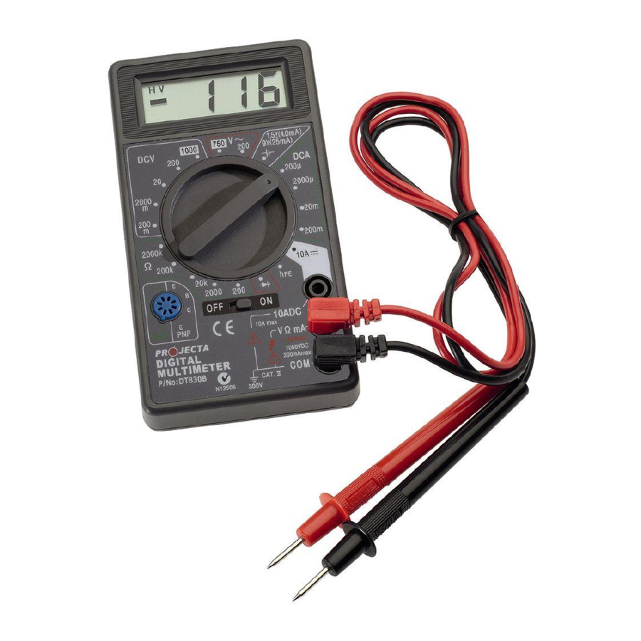
Projecta DT830B - Digital Multimeter Manual
- Information sheet (5 pages) ,
- Instruction manual (2 pages)
Advertisement
SAFETY

Do not exceed the meter's voltage or current limits. Use caution when testing voltages higher than 50VAC or 110VDC.
Do not use if the meter or test leads are damaged.
Remove test leads before replacing the battery or fuse.
NOTE: The DT830B should be stored below 60°C
SPECIFICATIONS
| Polarity: | Auto indication (-) |
| Voltage: | DCV: 200mV, 2000mV, 20V, 200V & 1000V |
| ACV: 200V & 750V (45-450Hz) | |
| Current: | DCA 200µA, 2000µA, 20mA, 200mA & 10A |
| Resistance: | 200Ohm, 2000Ohm, 20kOhm & 200kOhm |
| Dry cell battery check: | 1.5V (AAA, AA, C & D) & 9V |
| Diode test: | 1mA current for forward Vdrop |
| Transistor test: | hFE (0-1000) @ 3.2Vce |
| Accuracy: | < ± 1.0% full scale reading |
| Battery: | 9V Dry Cell |
| Internal Fuse: | M205 (F500mA) |
| Low battery warning: | 7.5V |
| Size: | 126mm X 69mm X 24mm |
| Weight: | 115g |
OPERATING INSTRUCTIONS
Controls
The 'ON/OFF' switch is used to turn the meter 'ON'. To conserve battery power, always turn the meter 'OFF' when not in use.
The parameter to be measured is selected using the rotary 'Function' switch.
For accuracy make sure the correct range is used. When the display shows '1' this indicates an over-range reading, use the next highest range.
Connecting Test Leads
There are three connection jacks, marked:
- 10ADC
- VΩmA
- COM
The BLACK test lead should be placed in the 'COM' jack.
For most measurements, except current over 200mA the RED test lead should be placed in the 'VΩmA' jack.
For current over 200mA but less than 10A the RED test lead should be placed in the '10ADC' jack.
MEASURING DC VOLTAGE
- Connect the RED test lead to the 'VΩmA' jack and the BLACK test lead to the 'COM' jack
- Set the Function switch to the correct 'DCV' range.
- Turn the meter 'ON'
- Connect the test probes across the Voltage to be measured.


MEASURING AC VOLTAGE
- Connect the RED test lead to the 'VΩmA' jack and the BLACK test lead to the 'COM' jack
- Set the Function switch to the correct 'ACV' range.
- Turn the meter 'ON'
- Connect the test probes across the Voltage to be measured.


BATTERY CHECK (DRY CELL, 1.5V & 9V)
- Connect the RED test lead to the 'VΩmA' jack and the BLACK test lead to the 'COM' jack
- Set the Function switch to the '
![]() ' setting.
' setting. - Turn the meter 'ON'
- Connect the test probes across the terminals of the battery to be measured, red probe to the (+) terminal of the battery.
- The meter will apply a small load to the battery and display the current in mA (if the reading is close to or above the following values, the battery is in good condition:
- 1.5V battery (AAA, AA, C, D) 4.0mA
- 9V battery 25mA
")
 ' setting.
")
MEASURING LOW DC CURRENT (<200MA)
- Connect the RED test lead to the 'VΩmA' jack and the BLACK test lead to the 'COM' jack
- Set the Function switch to the correct 'DCA' range.
- Turn the meter 'ON'
- Connect the test probes so that the meter becomes part of the circuit to be measured. If the load current is higher than 200mA the internal fuse will blow.
")
")
MEASURING DC CURRENT (UP TO 10A)
- Connect the RED test lead to the '10ADC' jack and the BLACK test lead to the 'COM' jack
- Set the Function switch to the '10A' setting.
- Turn the meter 'ON'
- Connect the test probes so that the meter becomes part of the circuit to be measured. Ensure that the circuit load is less than 10Amps or the meter will be damaged.
")
")
MEASURING RESISTANCE
- Connect the RED test lead to the 'VΩmA' jack and the BLACK test lead to the 'COM' jack
- Set the Function switch to the correct 'Ω' range.
- Turn the meter 'ON'
- Connect the test probes across the Resistance to be measured. Ensure that the component or circuit under test in not energised.


DIODE CHECK
- Connect the RED test lead to the 'VΩmA' jack and the BLACK test lead to the 'COM' jack
- Set the Function switch to the '
![]() ' setting.
' setting. - Turn the meter 'ON'
- Connect the test probes across the diode, Positive probe (RED) to the 'anode' and Negative probe (BLACK) to the 'Cathode'.
- If the diode is functioning the meter should display the diode forward Voltage drop, usually between 500–700mV.

 ' setting.
TRANSISTOR CHECK
- Set the Function switch to the 'hFE' setting.
- Turn the meter 'ON'
- Connect the component leads of the transistor to the correct pins of the transistor jack (Emitter, Base & Collector) depending on whether it is a NPN or PNP type; you may need the component specification sheets to help you identify this.
- The meter will display the hFE measurement.


Documents / ResourcesDownload manual
Here you can download full pdf version of manual, it may contain additional safety instructions, warranty information, FCC rules, etc.
Advertisement


Need help?
Do you have a question about the DT830B and is the answer not in the manual?
Questions and answers