Table of Contents
Advertisement
Installation, Operation, and Maintenance
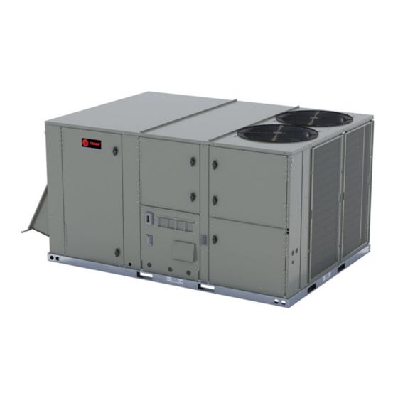
Packaged Rooftop Air Conditioners
Precedent™ Cooling and Gas/
Electric
Ultra High Efficiency
12.5 to 25 Tons – 60 Hz
Model Numbers: YZJ150* - YZJ300*
Only qualified personnel should install and service the equipment. The installation, starting up, and servicing of heating, ventilating, and air-conditioning equipment
can be hazardous and requires specific knowledge and training. Improperly installed, adjusted or altered equipment by an unqualified person could result in death or
serious injury. When working on the equipment, observe all precautions in the literature and on the tags, stickers, and labels that are attached to the equipment.
August 2023
SAFETY WARNING
RT-SVX077B-EN
Advertisement
Table of Contents

Related Manuals for Trane YZJ150


Summary of Contents for Trane YZJ150
- Page 1 Electric Ultra High Efficiency 12.5 to 25 Tons – 60 Hz Model Numbers: YZJ150* - YZJ300* SAFETY WARNING Only qualified personnel should install and service the equipment. The installation, starting up, and servicing of heating, ventilating, and air-conditioning equipment can be hazardous and requires specific knowledge and training. Improperly installed, adjusted or altered equipment by an unqualified person could result in death or serious injury.
- Page 2 (HCFCs). Not all refrigerants containing these compounds bump cap, fall protection, electrical PPE and arc have the same potential impact to the environment. Trane flash clothing). ALWAYS refer to appropriate advocates the responsible handling of all refrigerants.
- Page 3 This document and the information in it are the property of serious injury and equipment or property damage. Trane, and may not be used or reproduced in whole or in Do not store or use gasoline or other flammable part without written permission. Trane reserves the right to...
- Page 4 Table of Contents Model Number Description ....6 High Temperature Sensor (FIAHTST001*) ..... . . 11 General Information .
-
Page 5: Table Of Contents
Table of Contents Drain Pan Removal (Units with Condensate Gas Heat Units ......41 Overflow Switch Option) . - Page 6 Model Number Description Digit 1 — Unit Function Digit 12, 13 — Service Sequence Digit 18 — Through-the-Base Provisions Y = DX Cooling, Gas Heat ** = Factory Assigned 0 = No Through-the-Base Provisions A = Through-the-Base Electric B = Through-the-Base Gas Piping Digit 2 —...
- Page 7 Model Number Description Digit 25— System Monitoring Controls 0 = No Monitoring Control 1 = Clogged Filter Switch 2 = Condensate Overflow Switch 4 = Clogged Filter Switch and Condensate Overflow Switch Digit 26— Not Used Digit 27— Unit Hardware Enhancements 0 = No Enhancements 1 = Stainless Steel Drain Pan Digit 28—...
- Page 8 General Information Unit Inspection Note: Do not use the unit heater for temporary heat without first completing the start-up. To protect against loss due to damage incurred in transit, The manufacturer will not assume any responsibility for perform inspection immediately upon receipt of the unit. equipment damage resulting from condensate Check carefully for shipping damage.
- Page 9 General Information Compressor Nameplate Clogged Filter Switch (Optional) The unit mounted clogged filter switch monitors the The nameplate for the compressors are located on the side pressure differential across the return air filters. It is of the compressor. mounted in the filter section and is connected to the Fresh Air Options Module.
- Page 10 This sensor features remote zone sensing and timed When the LPC is opened for 1 continuous second, the override with override cancellation. It is used with a Trane compressor for that circuit is turned OFF. The compressor Integrated Comfort™ building management system.
- Page 11 General Information Smoke Detector Sensor High Temperature Sensor (FIAHTST001*) (Optional) This sensor connects to the Symbio™ 700 Emergency Stop Input and provides high limit “shutdown” of the unit. This sensor provides high limit shutdown of the unit and The sensor is used to detect high temperatures due to a requires a manual reset.
- Page 12 General Information – The power supply circuit is not balanced with the – The line to line voltage is not between 180 volts and proper phase sequence of L1, L2, L3 for the 3 633 volts. conductors of a 3 phase circuit. RT-SVX077B-EN...
- Page 13 Pre-Installation Precautionary Measures WARNING Fiberglass Wool! • Avoid breathing fiberglass dust. Exposure to glass wool fibers without all necessary • Use a NIOSH approved dust/mist respirator. PPE equipment could result in cancer, respiratory, • Avoid contact with the skin or eyes. Wear long-sleeved, skin or eye irritation, which could result in death or loose-fitting clothing, gloves, and eye protection.
- Page 14 Dimensions and Weights Dimensional Data Figure 2. 12.5 to 25 tons ultra high efficiency INDOOR TOP PANEL CONTROL BOX SECTION ACCESS PANEL OUTDOOR TOP PANEL COMPRESSOR SECTION ACCESS PANEL EVAPORATOR SECTION ACCESS PANEL 3/4" NPT GAS CONNECTION 2" ELECTRICAL CONNECTION 66'' HORIZONTAL ACCESS [1676]...
- Page 15 Dimensions and Weights Figure 4. 12.5 to 25 tons ultra high efficiency— gas pipe height Note: Height of gas pipe required from inside unit base to gas shut off assembly (factory provided). Dimension A Model inch YZJ (150 – 300)* 1 3/6 Figure 5.
- Page 16 Dimensions and Weights Figure 6. 12.5 to 25 tons ultra high efficiency – power exhaust 22.7 21.4 Figure 7. 12.5 to 25 tons ultra high efficiency – unit clearance and roof opening CLEARANCE 36” 914 MM UNIT OUTLINE CLEARANCE 68” 1727 MM CLEARANCE FORM TOP OF UNIT 72”...
- Page 17 Dimensions and Weights Figure 8. 12.5 to 25 tons ultra high efficiency – roof curb 116 7/8” 1” 2969 MM 25 MM 1 13/16” 1” 46 MM 25 MM 1 1/2” (38 MM) PERIMETER 22 1/4” CURB FLANGE 565 MM 23 1/4”...
- Page 18 Table 1. Model weights, corner weights (lbs) and center of gravity dimensions (in.) Model Weights Corner Weights Center of Gravity (in.) Tons Unit Model No. Shipping Length Width 12.5 YZJ150 2341 2121 YZJ180 2346 2126 17.5 YZJ210 2446 2226 YZJ240...
- Page 19 Center of Gravity Length Center of Gravity Width Center of Gravity Table 2. Factory installed options (FIOPS)/accessory net weights (lb) YZJ150-300 Accessory 12.5, 15, 17.5, 20, 25 Tons Barometric Relief Economizer Low Leak Economizer - Downflow Low Leak Economizer - Horizontal...
- Page 20 Dimensions and Weights Lifting and Rigging Figure 12. Rigging and center of gravity — 12.5 to 25 tons WARNING Heavy Object! Failure to follow instructions below could result in unit dropping which could result in death or serious injury, and equipment or property-only damage. Ensure that all the lifting equipment used is properly rated for the weight of the unit being lifted.
- Page 21 Installation Horizontal Units Elbows with turning vanes or splitters are recommended to minimize air noise due to turbulence and to reduce static If the unit is installed at ground level, elevate it above the pressure. snow line. Provide concrete footings at each support When attaching the ductwork to the unit, provide a water location with a full perimeter support structure or a slab tight flexible connector at the unit to prevent operating...
- Page 22 Installation Verify that appropriate materials were used in the Important: For unit protection, the top crate should construction of roof and ductwork. Combustible materials remain in place during lifting. If it must be should not be used in the construction of ductwork or roof removed prior to lifting, protect unit from curb that is in close proximity to heater elements or any hot damage.
- Page 23 Installation ☐ Check the unit for shipping damage and material Figure 16. Discard cover plate shortage. File a freight claim and notify appropriate sales representative. ☐ Verify correct model, options, and voltage from unit nameplate. ☐ Verify the installation location of the unit will provide the required clearance for proper operation.
- Page 24 Table 4. TCO1 tripping values – modulating gas TCO1 Tripping Values Unit Model Tons (3" Switch) Number Downflow/Horizontal 12.5 YZJ150***BH 125°F - 3" stilt YZJ180***BL 125°F - 3" stilt YZJ180***BH 140°F button Temperature Limit Switch Usage for Gas YZJ210***BL 125°F - 3" stilt Heat Units 17.5...
- Page 25 Installation Figure 19. TCO1 instructions Additional TCO1 limit switch to be used for horizontal discharge field conversion Location of TCO1 limit to be installed YZJ(150-300)***(0,A) (12.5 to 25 Ton Units) Note: The TCO1 switch is attached by two screws in the Figure 20.
- Page 26 Installation Air-Fi® Wireless Communication Note: Refer to horizontal views below of the 12.5 to 25 ton units. Interface Figure 21. Horizontal bracket installation (top view of The factory installed wireless communications interface is unit) installed in the downflow discharge position. If converting to horizontal discharge, perform the following: 1.
- Page 27 For variable frequency drives Table 5. Through-the-base gas piping dimension or other energy storing components provided by Trane or others, refer to the appropriate Dimension A (inch) Model manufacturer’s literature for allowable waiting periods...
- Page 28 (see Table 6, p. 28 Table 7, p. 28). Table 6. Gas heat data - supply and manifold pressure requirements – two-stage gas YZJ(180-300)* YZJ150* 150,000- Heating Input Rate – Btu/h 250,000 320,000 400,000 250,000 Minimum Supply Gas 4.5/11.5...
-
Page 29: Drain Pan Removal (Units With Condensate Overflow Switch Option)
Installation Figure 27. Condensate trap installation directly above the front control panel. It is not required to replace both motor pairs. Drain Pan Type Connection CABINET Figure 28. Location of outdoor motor controllers STAINLESS A/B/C 3/4" NPT 3/4" NPT Controller 1 linked to Motor 1 Controller 2 linked to Motor 2 1"... -
Page 30: Main Unit Power
Installation Main Unit Power Notes: • Black gasket is shipped from the factory and is WARNING located in the literature ship-with bag in the Proper Field Wiring and Grounding control box. Apply black gasket around conduit Required! plate on all four sides after installation to prevent air leakage from the building entering Failure to follow code could result in death or serious the electrical enclosures. -
Page 31: Controls Using 24 Vac
Installation WARNING 2. AC control wiring between the controls and the unit termination point should not exceed 2.5 ohms/ Hazardous Voltage! conductor for the length of the run. Failure to disconnect power before servicing could NOTICE result in death or serious injury. Disconnect all electric power, including remote Component Failure! disconnects before servicing. -
Page 32: Controls Using Dc Analog Input/Outputs (Standard Low Voltage Multi Conductor Wire)
Installation Figure 30. Main control panel low voltage wiring Table 8. Recommended wire lengths • Do not run the electrical wires transporting DC signals in or around conduit housing high voltage wires. Maximum recommended wire Wire Size length from unit controller to DC Conductors sensor Table 9. - Page 33 Installation sensors are required to accomplish space temperature • Example #3 illustrates the circuit required for this averaging. sensor. lists the temperature versus resistance coefficient for all sensors. Figure 31. Examples Note: Wiring pin numbers are for reference only. There are Table 10.
- Page 34 Installation Table 10. Temperature vs. resistance (continued) Table 11. Sizing natural gas pipe mains and branches (continued) Temperature Nominal Resistance Iron Pipe Size (IPS) Inches (kOhms) Degrees °F Degrees °C Length 1/2-in. 3/4-in. 1-in. 1¼-in. 1½-in. -1.1 34.85 of Pipe Pipe Pipe Pipe...
-
Page 35: Pre-Start
Pre-Start Use the checklist provided below in conjunction with the Excessive three phase voltage imbalance between General Unit Requirements checklist to confirm the unit is phases will cause motors to overheat and eventually properly installed and ready for operation. fail. The maximum allowable voltage imbalance is 2 percent. -
Page 36: Compressor Crankcase Heaters
Pre-Start WARNING switch or circuit protection switch and remove the phase sequence indicator. Hazardous Voltage w/Capacitors! Failure to disconnect power and discharge capacitors Compressor Crankcase Heaters before servicing could result in death or serious injury. • Each compressor can be equipped with a crankcase Disconnect all electric power, including remote heater (Some units include crankcase heater as disconnects and discharge all motor start/run... - Page 37 Pre-Start troubleshooting. The user can initiate Service Test Mode determine how long the controller will remain in any given through the controller user interfaces, including the Symbio state once initiated. For detailed information on how each Service and Installation mobile application. Service Test State is interpreted based on the equipment configuration, see ACC-APG002*-EN, Symbio™...
-
Page 38: Unit Start-Up
Unit Start-Up Sequence of Operation Table 13. Ignition module diagnostics (continued) See ACC-APG002*-EN, Application Guide, Symbio™ 700 System Lockout: Failed to detect or Controller with Precedent™ Packaged Rooftop Air- sustain flame. (failure to ignite, no 2 Flashes spark, low/no gas pressure, etc.) Conditioners. -
Page 39: Ignition And Operational Failures
Unit Start-Up a. < 1.5 Vdc (0% ModBus Firing Rate)]: OFF [A A 0 0 1 1 ], the controller enters an inter-purge period of 30 seconds [r r E E t t ] and then will initiate another ignition trial. b. -
Page 40: Return Air Smoke Detector
Unit Start-Up Display Code Code Type Description Additional Comments and Notes A A 0 0 3 3 Alert Insufficient Combustion Air Blocked vent with actuator position derated by >20% from FRI setting A A 0 0 4 4 Alert Limited Low Fire (due to Lost Flame Auto-Adaptation) Flame loss at low fire results in an auto-adjustment that limits the burner turn down during the rest of the current call for heat. -
Page 41: Hot Gas Reheat
Unit Start-Up 2. After the compressor and condenser fan have started 2. Follow the Test Guide in Figure 33, p. 37 to start the and operated for approximately 30 minutes, observe unit in the heating mode. the operating pressures. Compare the operating 3. -
Page 42: Maintenance
Maintenance Condensate Overflow Switch WARNING Hazardous Service Procedures! During maintenance, the switch float (black ring) must be checked to confirm free movement up and down. Failure to follow all precautions in this manual and on the tags, stickers, and labels could result in death or Cooling Season serious injury. -
Page 43: Coil Cleaning
Maintenance Microchannel (MCHE) Coils terminal connections, as well as damaged wire insulation. Make any necessary repairs. NOTICE • Verify the electric heat system operates properly. Coil Damage! Coil Cleaning Failure to follow instructions below could result in coil damage. Regular coil maintenance, including annual cleaning, DO NOT use any detergents with microchannel enhances the unit’s operating efficiency by minimizing the condenser coils. -
Page 44: Annual Maintenance
Maintenance Final Process 3. For compressor replacements and/or additional questions, contact Technical Support. For future reference, record the unit data below in the blanks provided. Annual Maintenance Clean and repaint any corroded surface. Table 14. Unit data log Complete Unit Model Number Unit Serial Number Wiring Diagram Numbers (from unit control panel) -
Page 45: Troubleshooting
Troubleshooting • Refer to the Application Guide Symbio™ 700 Controller • Refer to the Troubleshooting Guide Packaged Rooftop with Precedent™ Packaged Rooftop Air-Conditioners Air Conditioners Precedent™ eFlex™ Variable Speed (ACC-APG002*-EN). Compressor Inverter (RT-SVD008*-EN). RT-SVX077B-EN... -
Page 46: Wiring Diagrams
Wiring Diagrams Note: Wiring diagrams can be accessed using e-Library by number search field or by contacting technical entering the diagram number in the literature order support. Table 16. Wiring diagrams Schematic Type Voltage Drawing Number Description Controls SCHEMATIC; SHEET 1, POWER, DUAL COMPRESSOR, SINGLE Symbio 700 Main Unit 12134333... - Page 47 Wiring Diagrams Table 16. Wiring diagrams (continued) Schematic Type Voltage Drawing Number Description Controls Symbio 700 Main Unit 12134447 SCHEMATIC; SHEET 8, CONTROLS,STEPPER MOTOR CONTROLLER Symbio 700 SCHEMATIC; SHEET 9, CONTROLS, XM30/XM32 EXPANSION MODULES Main Unit 12134448 Symbio 700 LABEL; FUSE TABLE Main Unit X39004322 Main Unit...
- Page 48 Wiring Diagrams Table 16. Wiring diagrams (continued) Schematic Type Voltage Drawing Number Description Controls Component Location Symbio 700 12134450 DIAGRAM; COMPONENT LOCATION, GAS, B CABINET Component Location Symbio 700 DIAGRAM; COMPONENT LOCATION, COOLING/ELECTRIC, C CABINET 12134451 Component Location Symbio 700 DIAGRAM;...
-
Page 49: Piping Diagrams
Piping Diagrams Figure 34. Piping diagram – 12.5 to 15 tons ultra high efficiency (YZJ150–180) RT-SVX077B-EN... - Page 50 Piping Diagrams Figure 35. Piping diagram – 12.5 to 15 tons ultra high efficiency - hot gas reheat (YZJ150–180) RT-SVX077B-EN...
- Page 51 Piping Diagrams Figure 36. Piping diagram – 17.5 to 25 tons ultra high efficiency (YZJ210–300) RT-SVX077B-EN...
- Page 52 Piping Diagrams Figure 37. Piping diagram – 17.5 to 25 tons ultra high efficiency - hot gas reheat (YZJ210–300) RT-SVX077B-EN...
-
Page 53: Gas Heat Operation And Maintenance
Gas Heat Operation and Maintenance Gas Heat Unit General WARNING Information Safety Hazards! Failure to follow instructions below could result in WARNING death or serious injury. Hazard of Explosion or Fire! • Never perform any maintenance procedures until Failure to follow instructions could result in death or the electrical power to the unit is turned off. -
Page 54: Air Filters
(L x W x D) zone VAV operation but connected to a 20 x 24 x 2 thermostat, the control will revert to multi-speed YZJ150***(0,A,B)(L,M,H) 12.5 20 x 30 x 2 (two-speed) indoor fan control and staged compressor control. This drastically reduces... -
Page 55: Heating System Start-Up
For variable frequency drives your gas supplier, call the fire department. or other energy storing components provided by Trane or others, refer to the appropriate manufacturer’s literature for allowable waiting periods 7. Wait (five) minutes to clear out any gas. If you then for discharge of capacitors. -
Page 56: Turning Off Gas To Unit
Hazard of Explosion or Fire! equipment damage. Failure to follow instructions could result in death or Drain and vent coils when not in use. Trane serious injury and equipment or property damage. recommends glycol protection in all possible freezing Do not store or use gasoline or other flammable applications. -
Page 57: Condensate Overflow Sensor
Gas Heat Operation and Maintenance Condensate Overflow Sensor (Optional) If installed, the condensate overflow switch will shut down the unit before a drain pan overflow occurs. RT-SVX077B-EN... -
Page 58: Limited Warranty
This warranty is extended by Trane to the original be defective. purchaser and to any succeeding owner of the real... - Page 59 Notes RT-SVX077B-EN...
- Page 60 For more information, please visit trane. com or tranetechnologies.com. Trane has a policy of continuous product and product data improvements and reserves the right to change design and specifications without notice. We are committed to using environmentally conscious print practices.
Need help?
Do you have a question about the YZJ150 and is the answer not in the manual?
Questions and answers