Table of Contents
Advertisement
Quick Links
Advertisement
Table of Contents

Subscribe to Our Youtube Channel
Related Manuals for Arjo Classic Line 2


Summary of Contents for Arjo Classic Line 2
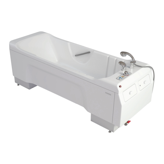
- Page 1 ASSEMBLY AND INSTALLATION INSTRUCTIONS Classic Line 2 06.ACL.00_3EN • 2023-09...
- Page 2 © Arjo 2023. As our policy is one of continuous improvement, we reserve the right to modify designs without prior notice. The content of this publication may not be copied either whole or in part without the consent of Arjo.
-
Page 3: Table Of Contents
Contents Safety instructions ............................4 Measurements and weights.......................... 5 Space requirements ............................. 7 Unpacking and assembly ..........................8 Electrical installation ........................... 10 Drain installation ............................13 Water installation ............................15 Calibration of the thermostat mixer......................18 Connecting the disinfectant bottle ......................21 .......................... -
Page 4: Safety Instructions
• • in accordance with local codes. • in accordance with local regulations. • all details are assembled corresponding to the assembly instructions. • all parts, which a user may come into contact with, are free from sharp edges. • all hoses, pipes, and connections are intact and free from water leakage. -
Page 5: Measurements And Weights
Classic Line 2 bathtub is delivered in one box. MEASUREMENTS, BOX WITH CONTENTS L = Length 2230 mm (87 3/4 in) H = Height 1059 mm (41 3/4 in) W = Width 910 mm (35 3/4 in) WEIGHT, BOX WITH CONTENTS... - Page 6 SIDE VIEW FRONT VIEW FRONT VIEW Width between feet 655 mm Width between lower covers 685 mm Max width between upper covers 805 mm Max width of bathtub 825 mm SIDE VIEW Width clearance, mid section 1285 mm Length between feet 1910 mm Length between lower covers 2040 mm...
-
Page 7: Space Requirements
The Classic Line 2 bathtub must always be installed according to the recommended space requirements, this to provide optimal working conditions for caregiver and patient. Make sure to order the requested parts depending on your setup. NOTE NOTE 300 mm / 12 in... -
Page 8: Unpacking And Assembly
1. Remove the wooden lid 2. Remove the box covering the bathtub CAUTION A. Bathtub B. Water hoses 1200 mm Article #6270395 - hot water and cold water C. Drain pipe D. Bottle with disinfectant (optional) E. Knob assembly kit F. - Page 9 Cable to main power bathtub. 2. Move the bathtub to its intended place. 3. Temporarily connect Classic Line 2 bathtub mains cable to the mains power. See Fig 2. See chapter “Electrical installation” on page 10. 4. Raise the bathtub to its highest position.
-
Page 10: Electrical Installation
WARNING WARNING WARNING WARNING WARNING WARNING WARNING WARNING WARNING WARNING ELECTRICAL INSTALLATION... - Page 11 ELECTRICAL INSTALLATION DATA Europe 230V single phase AC 50 Hz 1000VA 30mA MAINS DISCONNECTION DEVICE Permanently installed in wall. Visible and accessible at all times Mains transient voltage 4 kV* Creepage distance 3 mm* Air clearance 1.8 mm* Direction of movement Up and down, right and left, clockwise and counterclockwise * If local regulations are higher, then they have to be met.
- Page 12 If there is a requirement for a Booster Pump or a Multi Clean disinfection module then a separate 10A surface fused connection should be provided for each unit. In both instances a 5A fuse should be Refer to Arjo Technical Support in further detail is required. ELECTRICAL INSTALLATION...
-
Page 13: Drain Installation
DRAINAGE REQUIREMENTS The bathtub must be connected to a drainage. Use an air gap bracket, if needed. Connections must be done in accordance with local regulations. Recommended area 1. Cut the drain pipe to a suitable length according gap bracket, if needed. Remove the drain trap if not needed. - Page 14 the installation can be done as shown in order to shorten the distance between the water trap and the See Fig. 8 and 9. 1. Remove the water trap. Remove the two screws holding the drain bracket and turn it upside down. See Fig.
-
Page 15: Water Installation
NOTE NOTE WATER SUPPLY REQUIREMENT Max. static pressure 6 bar (600 kPa, 87 psi) Min. dynamic pressure 1 bar (100 kPa, 15 psi) 25 l/min (5.5 gal/min) 50 l/min CW + HW (11 gal/min CW + HW) Cold water temperature 8–20°C (46–68°F) Hot water temperature 60–80°C (140–176°F) - Page 16 (red handle) and other end Hot water inlet of the cold water hose to the cold bathtub inlet (blue handle). See Fig. 14. 4. Turn the handles to the open position (horizontal). 5. Push Classic Line 2 bathtub back into place. WATER INSTALLATION...
- Page 17 Due to the possibility of air in the MPA pump 6316295, after connecting the bathtub, perform the venting the following way: out. 2. After the water has been drained, close the cap and let the pump run for a few minutes. 3.
-
Page 18: Calibration Of The Thermostat Mixer
WARNING WARNING NOTE NOTE NOTE 1. Remove the calibration label fastened on the control panel. See Fig. 15. NOTE NOTE Turn the Calibration knob (A) counter clockwise and wait for the temperature display to read 43–44°C. See Fig. 17. 4. Measure the temperature with an external thermometer. - Page 19 7. Press the Shower ON/OFF button to start the shower. See Fig. 18. 8. Measure the shower water temperature with an external thermometer. Use only an calibrated external thermometer with an accuracy of ± 0.5°C. Make sure the water temperature reaches 40–41°C.
- Page 20 16. Push the Water temperature settings knob onto the Calibration knob. 17. Make sure the stop peg on the under side of the Water temperature settings knob (B) is placed right above the stop peg (E) on the black stop ring, see Fig.
-
Page 21: Connecting The Disinfectant Bottle
Fig 27. Arjo Clean (50) • Mixing ratio: Arjo Clean (50). 10. If necessary adjust the mixing ratio. See Fig. 28. 11. Put the spray handle back after use and put the covers back and lock. - Page 22 GENERAL Maximum patient weight 182 kg (400 lb) SWL Safe working load (resident + water) 415 kg (915 lb) Bathtub width 780 mm (31 in) Bathtub length 2185 mm (86 in) Bathtub weight (excluding package) 141 kg (310.9 lb) Package weight 40 kg (88.2 lb) Maximum height from tub to rim 1030 ±...
- Page 23 FUSE CONTROL BOX Fuse 6.3 A WATER 300 l 180 l 36 to 42 °C Minimum temperature range shower and disinfection shower 25 to 40 °C Thermometer display range 10 to 50 °C Accuracy of thermometer +/- 1°C 7 min 40 sec 18 min 30 sec 4 min 40 sec 11 min...
- Page 24 OPERATING CONDITIONS Air Humidity 30 to 95% Usage Temperature Range (Ambient) +5°C (41°F) to +35°C (95°F) Atmospheric Pressure 800 hPa to 1060 hPa TRANSPORT CONDITIONS Air Humidity 10% to 80% at 20 °C (68°F) Usage Temperature Range (Ambient) -20°C (-4°F) to +70°C (158°F) Atmospheric Pressure 500 hPa to 1100 hPa STORAGE CONDITIONS...
- Page 25 Intentionally left blank...
- Page 26 AUSTRALIA FRANCE Arjo Australia Arjo SAS Arjo Polska Sp. z o.o. Building B, Level 3 2 Avenue Alcide de Gasperi 11 Talavera Road CS 70133 Macquarie Park, NSW, 2113, FR-59436 RONCQ CEDEX Tel: +48 691 119 999 Australia Tél: +33 (0) 3 20 28 13 13 E-mail: arjo@arjo.com...
- Page 27 At Arjo, we believe that empowering movement within healthcare environments is essential to quality care. Our products and solutions are and the prevention of pressure injuries and venous thromboembolism. With over 6500 people worldwide and 65 years caring for patients and healthcare professionals, we are committed to driving healthier outcomes for people facing mobility challenges.
Need help?
Do you have a question about the Classic Line 2 and is the answer not in the manual?
Questions and answers