Table of Contents
Advertisement
Quick Links
Advertisement
Table of Contents

Related Manuals for Climer ECOFLEX TD EF02TD


Summary of Contents for Climer ECOFLEX TD EF02TD
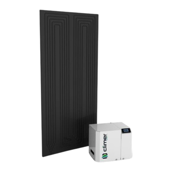
- Page 1 INSTALLATION AND USER MANUAL ECOFLEX TD EF02TD...
- Page 2 INSTALLATION AND USER MANUAL ECOFLEX TD V1REV5EN0922...
-
Page 3: Table Of Contents
INSTALLATION AND USER MANUAL ECOFLEX TD INTRODUCTION ......................1 GENERAL INDICATIONS ....................1 TECHNICAL INFORMATION .................... 3 INSTALLATION STEPS ....................5 THERMODYNAMIC SOLAR PANEL INSTALLATION ............6 PLACING ECOFLEX TD ....................8 CONNECTION BETWEEN ECOFLEX TD AND PANEL ..........10 HYDRAULIC CONNECTION .................. -
Page 4: Introduction
ECOFLEX TD 1. INTRODUCTION Thank you for buying a product manufactured by CLIMER TECHNOLOGY. This product has been manufactured according to the European Quality Standards, incorporates prime grade materials and its correct working has been tested before it leaves our facilities. - Page 5 The unit is supplied packed into a wooden pallet properly secured to prevent damage during transport. The material that CLIMER TECHNOLOGY uses to the packing are recyclables, so dispose it in an appropriate container. Use a forklift or hand pallet truck to transport the unit to the installation site, always introducing the forks into the bottom of the pallet being careful not to damage the unit.
-
Page 6: Technical Information
INSTALLATION AND USER MANUAL ECOFLEX TD 3. TECHNICAL INFORMATION 3.1. Operating Principle Figure 1. Operating principle 3.2. Dimension drawings Figure 2. Dimensions V1REV5EN0922... - Page 7 INSTALLATION AND USER MANUAL ECOFLEX TD Figure 3. Connections (removing the cover) Figure 4. Side connections A: Refrigerant outlet (1/4”) B: Refrigerant inlet (3/8”) C: Power supply D: Temperature probe / Pump connection E: Cold water inlet, 3/4’’ F: Hot water outlet, 3/4’’ V1REV5EN0922...
-
Page 8: Installation Steps
INSTALLATION AND USER MANUAL ECOFLEX TD 3.3. Technical data Model EF02TD Heat pump data Heating capacity range (1), W 1430 – 2560 Input power range (1), W 450 – 540 Energy Efficiency Class Load profile Maximum temp. HP, °C Refrigerant / Charge, kg R134A / 1.0 Minimum water flow, L/h Pressure drop (heat exchanger), kPa... -
Page 9: Thermodynamic Solar Panel Installation
INSTALLATION AND USER MANUAL ECOFLEX TD - Hydraulic installation components - Electric installation components Once it has been checked that it is available all the necessary components and tools, the installer should follow the next steps: 1. Placing and anchoring panel 2. - Page 10 INSTALLATION AND USER MANUAL ECOFLEX TD - Orientation: It is possible to install the panel both in vertical and horizontal position If the panel is installed at When the panel is installed in horizontal position, refrigerant vertical position, the inlet and inlet pipe should be connected outlet connection shall be always into the bottom connection.
-
Page 11: Placing Ecoflex Td
INSTALLATION AND USER MANUAL ECOFLEX TD - 18 x Washer 5 - 18 x Sheet Metal Screws - 18 x Blocks M6 Anchor the panel using the lateral and front holes to the suitable surface. 6. PLACING ECOFLEX TD The place where the system will be installed should allow an easy access to make maintenance work or inspection. - Page 12 INSTALLATION AND USER MANUAL ECOFLEX TD igure 6. Floor standing Figure 7. Wall mounted If the equipment is to be installed in the wall, be aware that a minimum distance between the water outlet of the tank and the outlet of ECOFLEX TD must be observed to ensure a good functioning of the pump and the equipment.
-
Page 13: Connection Between Ecoflex Td And Panel
INSTALLATION AND USER MANUAL ECOFLEX TD CONNECTION BETWEEN ECOFLEX TD AND PANEL a. Join refrigerant pipes Panels are supplied with two nuts for the inlet and outlet connection. The inlet to each panel is 1/4 inch diameter. The installer has to insert the nut into the copper pipe, flare the pipe and then use the nut to fit it. -
Page 14: Hydraulic Connection
INSTALLATION AND USER MANUAL ECOFLEX TD 8. HYDRAULIC CONNECTION The hydraulic connection depends on the existing buffer tank, if some type of connection for the recirculation or coil is available. The possible connections are detailed as follows: Figure 9. ECOFLEX TD connection on storage tank with two outlets Figure 10. - Page 15 INSTALLATION AND USER MANUAL ECOFLEX TD The installer must install the following components of the hydraulic circuit: - ECOFLEX TD (1) - Pump (8) - Gate valve (2) - Pressure gauge (9) - Check Valve (3) - Red water inlet (E) - Inclined filter (4) - DHW output (S) - Expansion vessel (5)
-
Page 16: Electrical Connection
INSTALLATION AND USER MANUAL ECOFLEX TD ELECTRICAL CONNECTION The power supply of the system is 230 V/1/50 Hz. PV: Photovoltaic connection LPS: Low pressure switch HPS: High pressure switch NTC1: Water temperature probe D: Display R: Electrical heater K: Compressor 230 VAC: Power supply P: Pump 9.1. -
Page 17: Comissioning. Controller
INSTALLATION AND USER MANUAL ECOFLEX TD COMISSIONING. CONTROLLER. S C R I P T I 10.1. User interface description Symbol Meaning when it lights Compressor switched on Defrost active. Not used. Fan switched on. Not used. Alarm active Compressor working hours exceeded Unit in ºC Unit in ºF Electric heater switched on... - Page 18 INSTALLATION AND USER MANUAL ECOFLEX TD 10.2. Installation - Switching on After full installation of the water heater (power and water pipes connected) and after the water heater tank is full of water, power can be turn ON. 1. After filling the tank of water, connect the mains plug to the mains supply.
- Page 19 INSTALLATION AND USER MANUAL ECOFLEX TD 10.4. Unlocking the keypad When 30 have elapsed without the keys being pressed, the display will show the ‘’ LOC’’ label and the keypad will lock automatically. Touch any key until the screen shows UnL, to unlock the keypad.
- Page 20 INSTALLATION AND USER MANUAL ECOFLEX TD 10.6. Changing operating mode To change the operating mode, touch the key for 4 seconds. The screen will show blinking the selectable operating modes. Use the keys to select the operating mode. Touch to confirm or to cancel.
- Page 21 INSTALLATION AND USER MANUAL ECOFLEX TD 10.7. ECO Mode ECO mode: Maximum savings. The system heats water only by heat pump technology. This is the factory default mode. Setting the ECO temperature setpoint The water temperature set point in ECO mode can be changed with the SP1 parameter. Touch key and select SP1.
- Page 22 INSTALLATION AND USER MANUAL ECOFLEX TD 10.8. AUTO Mode (ONLY IN COMBINATION WITH ELECTRICAL HEATER) It maintains a steady temperature by the heat pump and only use the electrical heater if the temperature falls drastically. Setting the AUTO temperature setpoint The water temperature set point in AUTO mode can be changed with the SP2 parameter.
- Page 23 INSTALLATION AND USER MANUAL ECOFLEX TD 10.9. OVERBOOST Mode (ONLY IN COMBINATION WITH ELECTRICAL HEATER) Select this mode to achieve a fast heating by using simultaneously heat pump and electric heater. This mode works as a rapid heating. Once the setpoint temperature is reached, the system returns to the initial mode.
- Page 24 INSTALLATION AND USER MANUAL ECOFLEX TD Parameter SP3 allows to set the minimum temperature that Overboost can be actived. To change it value, follow the procedure: Touch and select with SP3. Touch to confirm. The display will show the programmed temperature.
- Page 25 INSTALLATION AND USER MANUAL ECOFLEX TD 10.10. Photovoltaic input Working on this mode, the system automatically heats the water due to electric energy surplus or by Off Peak rate. The parameters of this mode can only be changed by the Installer’s Menu. Contact with the technician for more information.
- Page 26 INSTALLATION AND USER MANUAL ECOFLEX TD 10.12. Antilegionella The anti-legionnella feature reduces the risk of development of bacteria in the tank. The system performs a thermal shock disinfection to avoid any risk conditions that might cause the development of bacteria. The disinfection is made automatically once a week, reaching a temperature of 62 ºC.
-
Page 27: Warranty Conditions
INSTALLATION AND USER MANUAL ECOFLEX TD 11. WARRANTY CONDITIONS. WARRANTY PERIOD Component Warranty period Electrical, electronic, and mechanical removable components 2 years Evaporator panel 5 years WARRANTY CONDITIONS The warranty exclusively covers productions faults of the product, excluding any liability for any material damage or injury that results directly or indirectly from the use of this product. - Page 28 CLIMER TECHNOLOGY S.L.L. This company reserves the right to modify the information contained herein without prior notice.
Need help?
Do you have a question about the ECOFLEX TD EF02TD and is the answer not in the manual?
Questions and answers