Table of Contents
Advertisement
Quick Links
Advertisement
Table of Contents

Related Manuals for Lenovo ThinkSystem DG5000


Summary of Contents for Lenovo ThinkSystem DG5000
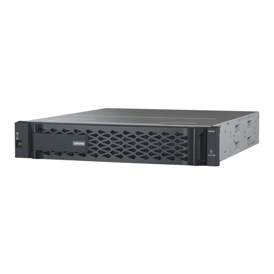
- Page 1 ThinkSystem DG5000 Hardware Installation and Maintenance Guide Machine Type: 7DE4...
- Page 2 Before using this information and the product it supports, be sure to read and understand the safety information and the safety instructions, which are available at: http://thinksystem.lenovofiles.com/help/topic/safety_documentation/pdf_files.html In addition, be sure that you are familiar with the terms and conditions of the Lenovo warranty for your system, which can be found at: http://datacentersupport.lenovo.com/warrantylookup First Edition (July 2023) ©...
-
Page 3: Table Of Contents
Scan system ....Installing the controller module ..Test system ....© Copyright Lenovo 2023... - Page 4 Before you call ....Collecting service data ... . 100 Contacting Support ... . . 100 ThinkSystem DG5000 Hardware Installation and Maintenance Guide...
-
Page 5: Safety
Vor der Installation dieses Produkts die Sicherheitshinweise lesen. Prima di installare questo prodotto, leggere le Informazioni sulla Sicurezza. Les sikkerhetsinformasjonen (Safety Information) før du installerer dette produktet. Antes de instalar este produto, leia as Informações sobre Segurança. © Copyright Lenovo 2023... - Page 6 Antes de instalar este producto, lea la información de seguridad. Läs säkerhetsinformationen innan du installerar den här produkten. ThinkSystem DG5000 Hardware Installation and Maintenance Guide...
-
Page 7: Chapter 1. Introduction
• Memory: 64 GB per node, 128 GB in total • NVRAM: 8 GB per node, 16 GB in total • Type: – DDR4-2666, dual-rank, 32 GB ECC RDIMM Note: 8 GB of NVRAM used from controller 64 GB memory. © Copyright Lenovo 2023... - Page 8 – Operating: ASHRAE class A2: 8%–80%; maximum dew point: 21°C (70°F) – Shipping or storage: 10%–95% Your storage complies with ASHARE class A2 specifications. For detailed information, see “ASHRAE class compliance information” on page 108. ThinkSystem DG5000 Hardware Installation and Maintenance Guide...
- Page 9 Chapter 1 Introduction...
-
Page 10: Management Software
Tech Tips Lenovo continually updates the support website with the latest tips and techniques that you can use to solve issues that you might have with your system. These Tech Tips (also called retain tips or service bulletins) provide procedures to work around issues related to the operation of your system. -
Page 11: Chapter 2. System Components
The system attention LED provides basic diagnostic functions for your storage system. If the system attention LED is lit, one or more LEDs elsewhere in the system might also be lit to direct you to the source of the error. © Copyright Lenovo 2023... -
Page 12: Rear View
The shelf ID is used to show the ID number of the shelf. Each shelf in a configuration needs to have a unique Rear view The rear view of the storage provides access to the system connectors and components. ThinkSystem DG5000 Hardware Installation and Maintenance Guide... - Page 13 Figure 2. Rear view with dual, high availability, nodes Top controller, node A Bottom controller, node B Figure 3. Rear view of controller nodes Host Interface Card slot 1 Host Interface Card slot 2 Power Supply RJ-45 console port USB Type-A port Micro-USB console port 1 GbE RJ-45 management port 10 Gbase-T Ethernet RJ45 ports (2)
-
Page 14: Rear View Leds
A link is established between the port and link LED some upstream device. None No link is established. RJ45 management port Blinking Green Traffic is flowing over the connection. activity LED None No traffic is flowing over the connection. ThinkSystem DG5000 Hardware Installation and Maintenance Guide... - Page 15 NVMEM discharge LED The NVMEM discharge LED provides the status of ONTAP running on the controller. Status Color Description Blinking Green NVMEM destage events are occurring. Solid Green NVMEM destage events completed successfully. None The system is running normally and the NVMEM is ready if ONTAP is running.
-
Page 16: Pcie Slots
HIC, 16/32Gb 4C57A67133 BEVP SFP+ Fibre Channel FC,4-ports 8/16/32 Gb NVMe/FC 8/ 16/32 Gb Expansion HIC, 2x100Gb 4C57A67134 BEVR QSFP28 Ethernet NVMe-RoCE,2- 100Gb ports : Used with DM240N expansion, restricted to 100 GbE only. ThinkSystem DG5000 Hardware Installation and Maintenance Guide... -
Page 17: Chapter 3. System Installation And Setup
You need to have access to the Lenovo Press for information about site requirements as well as additional information on your configured system. Lenovo Press Attention: Customers with specific power requirements must check Lenovo Press for their configuration options. -
Page 18: Installing The Hardware
DG5000 Installation and Setup Instructions Cluster Management Using ThinkSystem Storage Manager for DM Series Installing the hardware You need to install your system in a 4-post rack or Lenovo system cabinet, as applicable. Step 1. Install the rail kits, as needed. -
Page 19: Cabling Controllers
Step 3. Identify and manage cables because this system does not have a cable management device. Step 4. Place the bezel on the front of the system. Cabling controllers There is required cabling for your platform's cluster using the two-node switchless cluster method or the cluster interconnect network method. - Page 20 Cable the cluster interconnect ports to each other with the 25GbE cluster interconnect cable • e0c to e0c • e0d to e0d Cable ports 1a through 1d to data or host network switches: Cable ports 2a through 2d to the FC host network switches: ThinkSystem DG5000 Hardware Installation and Maintenance Guide...
- Page 21 Step Perform on each controller Cable the wrench ports to the management network switches with the RJ45 cables. DO NOT plug in the power cords at this point. Step 2. To complete setting up your system, see “Completing system setup and configuration” on page 20 Cabling a switched cluster All ports on the controllers are connected to switches;...
- Page 22 Cable the cluster interconnect ports to the 25 GbE cluster interconnect switches. • e0c • e0d Cable ports 1a through 1d to data or host network switches: Cable ports 2a through 2d to the FC host network switches: ThinkSystem DG5000 Hardware Installation and Maintenance Guide...
- Page 23 Step Perform on each controller Cable the wrench ports to the management network switches with the RJ45 cables. DO NOT plug in the power cords at this point. Step 2. To complete setting up your system, see “Completing system setup and configuration” on page Cabling configuration-dependant options You have configuration-dependant optional cabling to the Fibre Channel or iSCSI host networks or direct- attached storage.
- Page 24 Be sure to check the illustration arrow for the proper cable connector pull-tab orientation. Pull-tab Note: As you insert the connector, you should feel it click into place; if you do not feel it click, remove it, turn it around and try again. ThinkSystem DG5000 Hardware Installation and Maintenance Guide...
- Page 25 Step Perform on each controller module Cable ports e1a through e1d to the 10GbE host network switches. To perform other optional cabling, choose from: • “Cabling to a Fibre Channel host network” on page 17 • “Cabling the controllers to a single drive shelf” on page 19 To complete setting up your system, see “Completing system setup and configuration”...
-
Page 26: Completing System Setup And Configuration
Note: See your laptop or console's online help for how to configure the console port. Connect the console cable to the laptop or console using the console cable that came with your system, and then connect the laptop to the management switch on the management subnet . ThinkSystem DG5000 Hardware Installation and Maintenance Guide... - Page 27 Assign a TCP/IP address to the laptop or console, using one that is on the management subnet. Step 2. Plug the power cords into the controller power supplies, and then connect them to power sources on different circuits.The system begins to boot. Initial booting may take up to eight minutes Step 3.
- Page 28 ThinkSystem DG5000 Hardware Installation and Maintenance Guide...
-
Page 29: Chapter 4. Hardware Replacement Procedures
CAUTION: The power supply is short. Always use two hands to support it when removing it from the controller module so that it does not suddenly swing free from the controller module and injure you. © Copyright Lenovo 2023... -
Page 30: Completing The Replacement Process
Once power is restored to the power supply, the status LED should be green. Completing the replacement process After you replace the part, you can return the failed part to Lenovo, as described in the RMA instructions shipped with the kit.Contact technical support at... -
Page 31: Replacing A Fan
Replacing a fan Shutting down the impaired node To shut down the impaired node, you must determine the status of the node and, if necessary, take over the node so that the healthy node continues to serve data from the impaired node storage. •... -
Page 32: Replacing A Fan
Thumbscrew Controller module cover Replacing a fan To replace a fan, remove the failed fan module and replace it with a new fan module. A video for this task is available at: ThinkSystem DG5000 Hardware Installation and Maintenance Guide... -
Page 33: Reinstalling The Controller Module
• YouTube: https://www.youtube.com/playlist?list=PLYV5R7hVcs-C8THdP1nmPF25RWwGRta3v Step 1. Identify the fan module that you must replace by checking the console error messages or by locating the lit LED for the fan module on the motherboard. Step 2. Remove the fan module by pinching the locking tabs on the side of the fan module, and then lifting the fan module straight out of the controller module. - Page 34 The controller module should be fully inserted and flush with the edges of the chassis. Step 3. Recable the system, as needed. Step 4. Return the node to normal operation by giving back its storage from the running node: storage failover giveback -ofnode impaired_node_name ThinkSystem DG5000 Hardware Installation and Maintenance Guide...
-
Page 35: Completing The Replacement Process
-node local -auto-giveback true Completing the replacement process After you replace the part, you can return the failed part to Lenovo, as described in the RMA instructions shipped with the kit.Contact technical support at if you need the RMA number or Lenovo Data Center Support additional help with the replacement procedure. -
Page 36: Shutting Down The Impaired Controller
Unplug the controller module power supplies from the source. Step 3. Release the power cable retainers, and then unplug the cables from the power supplies. Step 4. Remove the storage and networking cables. ThinkSystem DG5000 Hardware Installation and Maintenance Guide... - Page 37 Step 5. Insert your forefinger into the latching mechanism on either side of the controller module, press the lever with your thumb, and gently pull the controller a few inches out of the chassis. Note: If you have difficulty removing the controller module, place your index fingers through the finger holes from the inside (by crossing your arms) Lever Latching mechanism...
- Page 38 You must move the power supplies from the impaired controller module to the replacement controller module when you replace a controller module. A video for this task is available at: • YouTube: https://www.youtube.com/playlist?list=PLYV5R7hVcs-C8THdP1nmPF25RWwGRta3v ThinkSystem DG5000 Hardware Installation and Maintenance Guide...
- Page 39 Step 1. Rotate the cam handle such that it can be used to pull power supply out of the controller module while pressing the locking tab. CAUTION: The power supply is short. Always use two hands to support it when removing it from the controller module so that it does not suddenly swing free from the controller module and injure you.
- Page 40 Use the screwdriver or your thumb to tighten the screw on the boot media. Moving the DIMMs To move the DIMMs, locate and move them from the impaired controller into the replacement controller and follow the specific sequence of steps. ThinkSystem DG5000 Hardware Installation and Maintenance Guide...
- Page 41 A video for this task is available at: • YouTube: https://www.youtube.com/playlist?list=PLYV5R7hVcs-C8THdP1nmPF25RWwGRta3v Step 1. Move the DIMMs from the impaired controller module to the replacement controller module: Important: Install each DIMM into the same slot it occupied in the impaired controller module. Slowly push apart the DIMM ejector tabs on either side of the DIMM, and slide the DIMM out of the slot.
- Page 42 Moving the NV battery When replacing the controller module, you must move the NV battery from the impaired controller module to the replacement controller module A video for this task is available at: • YouTube: https://www.youtube.com/playlist?list=PLYV5R7hVcs-C8THdP1nmPF25RWwGRta3v ThinkSystem DG5000 Hardware Installation and Maintenance Guide...
- Page 43 Step 1. Locate and move the NVMEM battery from your impaired controller module to the replacement controller module. Squeeze the clip on the face of the battery plug. Unplug the battery cable from the socket. Grasp the battery and press the blue locking tab marked PUSH. Lift the battery out of the holder and controller module.
- Page 44 You can use the following steps to install the replacement controller module in the chassis. A video for this task is available at: • YouTube: https://www.youtube.com/playlist?list=PLYV5R7hVcs-C8THdP1nmPF25RWwGRta3v Step 1. If you have not already done so, close the air duct. ThinkSystem DG5000 Hardware Installation and Maintenance Guide...
- Page 45 Step 2. Close the controller module cover and tighten the thumbscrew. Controller module cover Thumbscrew Step 3. Align the end of the controller module with the opening in the chassis, and then gently push the controller module halfway into the system. Note: Do not completely insert the controller module in the chassis until instructed to do so.
-
Page 46: Running Diagnostics
Reboot Completing the replacement process After you replace the part, you can return the failed part to Lenovo, as described in the RMA instructions shipped with the kit.Contact technical support at if you need the RMA number or Lenovo Data Center Support additional help with the replacement procedure. -
Page 47: Shutting Down The Impaired Controller
Shutting down the impaired controller You can shut down or take over the impaired controller using different procedures, depending on the storage system hardware configuration. Shutting down the impaired node To shut down the impaired node, you must determine the status of the node and, if necessary, take over the node so that the healthy node continues to serve data from the impaired node storage. - Page 48 Using both hands, grasp the controller module sides and gently pull it out of the chassis and set it on a flat, stable surface. Step 7. Turn the thumbscrew on the front of the controller module anti-clockwise and open the controller module cover. Thumbscrew Controller module cover ThinkSystem DG5000 Hardware Installation and Maintenance Guide...
-
Page 49: Replacing A Dimm
Step 8. Lift out the air duct cover. Replacing a DIMM To replace a DIMM, you must locate it in the controller module using the DIMM map label on top of the air duct or locating it using the LED next to the DIMM, and then replace it following the specific sequence of steps. -
Page 50: Installing The Controller Module
You can use the following steps to install the replacement controller module in the chassis. A video for this task is available at: • YouTube: https://www.youtube.com/playlist?list=PLYV5R7hVcs-C8THdP1nmPF25RWwGRta3v Step 1. If you have not already done so, close the air duct. ThinkSystem DG5000 Hardware Installation and Maintenance Guide... - Page 51 Chapter 4 Hardware replacement procedures...
- Page 52 Cable the management and console ports only, so that you can access the system to perform the tasks in the following sections. Note: You will connect the rest of the cables to the controller module later in this procedure. ThinkSystem DG5000 Hardware Installation and Maintenance Guide...
-
Page 53: Running Diagnostics
Reboot Completing the replacement process After you replace the part, you can return the failed part to Lenovo, as described in the RMA instructions shipped with the kit.Contact technical support at if you need the RMA number or Lenovo Data Center Support additional help with the replacement procedure. -
Page 54: Pre-Shutdown Checks For Onboard Encryption Keys
Checking LVE or LSE on systems running ONTAP 9.6 and later Before shutting down the impaired node, you need to check whether the system has either Lenovo Volume Encryption (LVE) or Lenovo Storage Encryption (LSE) enabled. If so, you need to verify the configuration. - Page 55 KeyManager external Restored Restore the external key management authentication keys to all nodes in the cluster: security If the command fails, contact Lenovo Support. key-manager external restore https://datacentersupport.lenovo.com/ Verify that the column equals for all authentication keys:...
-
Page 56: Shutting Down The Impaired Controller
You can shut down or take over the impaired controller using different procedures, depending on the storage system hardware configuration. Completing node shutdown After completing the LVE or Lenovo Storage Encryption (LSE) tasks, you need to complete the shutdown of the impaired node. ThinkSystem DG5000 Hardware Installation and Maintenance Guide... -
Page 57: Removing The Controller Module
Step 1. If the impaired node isn't at the LOADER prompt: If the impaired node displays... Then... Press Ctrl-C, and then respond when Waitingforgiveback::: prompted. Take over or halt the impaired node: System prompt or password prompt (enter system password) •... - Page 58 Using both hands, grasp the controller module sides and gently pull it out of the chassis and set it on a flat, stable surface. Step 7. Turn the thumbscrew on the front of the controller module anti-clockwise and open the controller module cover. Thumbscrew Controller module cover ThinkSystem DG5000 Hardware Installation and Maintenance Guide...
-
Page 59: Replacing The Boot Media
Step 8. Lift out the air duct cover. Replacing the boot media You locate the failed boot media in the controller module by removing the air duct on the controller module before you can replace the boot media. You need a #1 magnetic Phillips head screw driver to remove the screw that holds the boot media in-place. Due to the space constraints within the controller module, you should also have a magnet to transfer the screw on to so that you do not loose it. - Page 60 • A copy of the same image version of ONTAP as what the impaired controller was running. You can download the appropriate image from the Downloads section on the Lenovo Data Center Support Site – If NVE is enabled, download the image with Lenovo Volume Encryption, as indicated in the download button.
- Page 61 Step 2. If you have not already done so, close the air duct. Chapter 4 Hardware replacement procedures...
- Page 62 The controller module begins to boot as soon as it is fully seated in the chassis. Be prepared to interrupt the boot process. The controller module should be fully inserted and flush with the edges of the chassis. ThinkSystem DG5000 Hardware Installation and Maintenance Guide...
-
Page 63: Booting The Recovery Image
Step 9. Check that all required boot environment variables and bootargs are properly set for your system type and configuration using the command and correct any errors using the printenv bootarg name command. setenv variable-name <value> Check the boot environment variables: •... - Page 64 Connected for the target iSCSI-target (type: dr_partner, address: ip-address). 4. Select the Update flash from backup config (sync flash) option from the displayed menu. If you are prompted to continue with the update, press ThinkSystem DG5000 Hardware Installation and Maintenance Guide...
-
Page 65: Completing The Replacement Process
Completing the replacement process After you replace the part, you can return the failed part to Lenovo, as described in the RMA instructions shipped with the kit.Contact technical support at Lenovo Data Center Support if you need the RMA number or additional help with the replacement procedure. -
Page 66: Replacing The Real-Time Clock Battery
You must remove the controller module from the chassis when you replace a component inside the controller module. Make sure that you label the cables so that you know where they came from. A video for this task is available at: • YouTube: https://www.youtube.com/playlist?list=PLYV5R7hVcs-C8THdP1nmPF25RWwGRta3v ThinkSystem DG5000 Hardware Installation and Maintenance Guide... - Page 67 Step 1. If you are not already grounded, properly ground yourself. Step 2. Unplug the controller module power supplies from the source. Step 3. Release the power cable retainers, and then unplug the cables from the power supplies. Step 4. Remove the storage and networking cables.
- Page 68 Step 7. Turn the thumbscrew on the front of the controller module anti-clockwise and open the controller module cover. Thumbscrew Controller module cover Step 8. Lift out the air duct cover. ThinkSystem DG5000 Hardware Installation and Maintenance Guide...
-
Page 69: Replacing The Rtc Battery
Replacing the RTC battery To replace the RTC battery, locate it inside the controller and follow the specific sequence of steps. A video for this task is available at: • YouTube: https://www.youtube.com/playlist?list=PLYV5R7hVcs-C8THdP1nmPF25RWwGRta3v Step 1. Locate the RTC battery between the heatsink and the midplane and remove it exactly as shown in the graphic. -
Page 70: Reinstalling The Controller Module
After you replace a component within the controller module, you must reinstall the controller module in the system chassis and boot it. A video for this task is available at: • YouTube: https://www.youtube.com/playlist?list=PLYV5R7hVcs-C8THdP1nmPF25RWwGRta3v ThinkSystem DG5000 Hardware Installation and Maintenance Guide... - Page 71 Step 1. Close the controller module cover and tighten the thumbscrew. Controller module cover Thumbscrew Step 2. Insert the controller module into the chassis: Ensure the latching mechanism arms are locked in the fully extended position. Using both hands, align and gently slide the controller module into the latching mechanism arms until it stops.
-
Page 72: Completing The Replacement Process
-node local -auto-giveback true Completing the replacement process After you replace the part, you can return the failed part to Lenovo, as described in the RMA instructions shipped with the kit.Contact technical support at if you need the RMA number or Lenovo Data Center Support additional help with the replacement procedure. -
Page 73: Removing The Controller Module
If the impaired node is displaying... Then... The LOADER prompt Go to the next step. Waiting for giveback... Press Ctrl-C, and then respond Take over or halt the impaired node: System prompt or password prompt (enter storage system password) failover takeover -ofnode impaired_node_name When the impaired node shows Waiting for giveback..., press Ctrl-C, and then respond Removing the controller module... - Page 74 Using both hands, grasp the controller module sides and gently pull it out of the chassis and set it on a flat, stable surface. Step 7. Turn the thumbscrew on the front of the controller module anti-clockwise and open the controller module cover. Thumbscrew Controller module cover ThinkSystem DG5000 Hardware Installation and Maintenance Guide...
-
Page 75: Replacing Or Installing A Mezzanine Card
Step 8. Lift out the air duct cover. Replacing or installing a mezzanine card To replace a mezzanine card, which is also referred to as a host interface card (HIC), you must remove the impaired card and install the replacement card; to install a mezzanine card, you must remove the face plate and install the new card. -
Page 76: Reinstalling The Controller Module
Press your thumbs down on the orange tabs on top of the latching mechanism and gently push the controller module over the stop. Release your thumbs from the top of the latching mechanisms and continue pushing until the latching mechanisms snap into place. ThinkSystem DG5000 Hardware Installation and Maintenance Guide... -
Page 77: Completing The Replacement Process
-node local -auto-giveback true Completing the replacement process After you replace the part, you can return the failed part to Lenovo, as described in the RMA instructions shipped with the kit.Contact technical support at if you need the RMA number or Lenovo Data Center Support additional help with the replacement procedure. -
Page 78: Removing The Controller Module
Note: If you have difficulty removing the controller module, place your index fingers through the finger holes from the inside (by crossing your arms) Lever Latching mechanism ThinkSystem DG5000 Hardware Installation and Maintenance Guide... -
Page 79: Replacing The Nv Battery
Step 6. Using both hands, grasp the controller module sides and gently pull it out of the chassis and set it on a flat, stable surface. Step 7. Turn the thumbscrew on the front of the controller module anti-clockwise and open the controller module cover. -
Page 80: Installing The Controller Module
Maintenance mode. You can use the following steps to install the replacement controller module in the chassis. A video for this task is available at: ThinkSystem DG5000 Hardware Installation and Maintenance Guide... - Page 81 • YouTube: https://www.youtube.com/playlist?list=PLYV5R7hVcs-C8THdP1nmPF25RWwGRta3v Step 1. Close the controller module cover and tighten the thumbscrew. Controller module cover Thumbscrew Step 2. Insert the controller module into the chassis: Ensure the latching mechanism arms are locked in the fully extended position. Using both hands, align and gently slide the controller module into the latching mechanism arms until it stops.
-
Page 82: Running Diagnostics
Reboot Completing the replacement process After you replace the part, you can return the failed part to Lenovo, as described in the RMA instructions shipped with the kit.Contact technical support at if you need the RMA number or Lenovo Data Center Support additional help with the replacement procedure. -
Page 83: Removing The Controller Modules
Shutting down the nodes You must shut down the nodes in the chassis prior to moving them to the new chassis. • If you have a cluster with more than two nodes, it must be in quorum. If the cluster is not in quorum or a healthy node shows false for eligibility and health, you must correct the issue before shutting down the impaired node. -
Page 84: Moving Drives To The New Chassis
Be sure to close the cam handle slowly so that it aligns correctly with the front of the drive carrier. It will click when it is secure. ThinkSystem DG5000 Hardware Installation and Maintenance Guide... -
Page 85: Replacing A Chassis From Within The Equipment Rack Or System Cabinet
Step 6. Repeat the process for the remaining drives in the system. Replacing a chassis from within the equipment rack or system cabinet You must remove the existing chassis from the equipment rack or system cabinet before you can install the replacement chassis. -
Page 86: Running Diagnostics
Reboot Completing the replacement process After you replace the part, you can return the failed part to Lenovo, as described in the RMA instructions shipped with the kit.Contact technical support at if you need the RMA number or Lenovo Data Center Support additional help with the replacement procedure. -
Page 87: Chapter 5. System Level Diagnostics
When you scan the system, system-level diagnostics obtains an accurate hardware inventory of the system. You must scan the system first, before you run any tests. To execute the "Scan system" operation, type "1" and then press "Enter" to start the system scan. © Copyright Lenovo 2023... - Page 88 The scan system summary provides general information about the hardware inventory present in the system. Press "Enter" to return to the main menu after the scan is complete. ThinkSystem DG5000 Hardware Installation and Maintenance Guide...
- Page 89 Chapter 5 System level diagnostics...
-
Page 90: Test System
– Run– Run the selected tests from the Test System page – Test All– Run all available system tests – Cancel– Cancel system test and return to the main menu. • Press "Enter" to execute your choice. ThinkSystem DG5000 Hardware Installation and Maintenance Guide... -
Page 91: Test Example: Run Cpu Test
If "Run" or "Test All" is chosen, the "Configure Test Loop" page is displayed. • Enter the number of test loops for the selected tests. • Use the "Tab" key to switch the cursor between the loop input panel and the page control panel. •... -
Page 92: Test Memory
The test results are displayed on the console, as shown below. Press "Enter" to return to the main menu. Test memory The "Test memory" command allows you to run tests on part or all of system memory. To execute the "Test Memory" operation, type "3" and then press "Enter". ThinkSystem DG5000 Hardware Installation and Maintenance Guide... -
Page 93: Configure Memory Test Range
Configure Memory Test Range Use the Configure Memory Test Range to specify the start and the end addresses for the memory tests. • Fill in the "Start Address" and "End Address" fields with the desired memory address range (in hexadecimal). •... - Page 94 • Use the "space" bar to toggle an option on or off. • Use the left and right arrow keys to select "Run" or "Cancel". • Press "Enter" to execute your choice. If "Run" is chosen, the "Configure Test Loop" page is displayed. ThinkSystem DG5000 Hardware Installation and Maintenance Guide...
- Page 95 • Enter the number of test loops for the selected tests. Note: For the "Memory Random Test", this value specifies the number of seconds spent running the test. • Use the "Tab" key to switch the cursor between the loop input panel and the page control panel. •...
-
Page 96: Show Vpd Information
Show VPD information The "Show VPD information" command displays vital product data (VPD) information for components of the system. To execute the "Show VPD information" operation, type "5" and then press "Enter". ThinkSystem DG5000 Hardware Installation and Maintenance Guide... - Page 97 VPD information is displayed. Press "Enter" to return to the main menu. Chapter 5 System level diagnostics...
-
Page 98: Show Fw Revision
Show FW revision The "Show FW revision" command displays the firmware revision information for components in the system. To execute the "Show FW revision" operation, type "6" and then press "Enter". ThinkSystem DG5000 Hardware Installation and Maintenance Guide... -
Page 99: Show Mac Address
The FW revision is displayed. Press "Enter" to return to the main menu. Show MAC address The "Show MAC address" command displays the unique MAC addresses allocated to components in the system. To execute the "Show MAC address" operation, type "7" and then press "Enter". Chapter 5 System level diagnostics... -
Page 100: Show Logs
The last ten results for each scan or test command are available for review. To execute the "Show logs" operation, type "8" and then press "Enter" to go to the "Show Logs" page. ThinkSystem DG5000 Hardware Installation and Maintenance Guide... -
Page 101: Show Logs Selection
Show Logs Selection • Use the "up" and "down" arrow keys to select the log types to display. • Use the "space" bar to toggle an option on or off. • Use the left and right arrow keys to select "Show" or "Cancel". •... - Page 102 The logs are displayed, shown as below. Use the following keys to control the displayed log output: • PgUp/PgDn – Scroll up or down page by page • Up/Down Arrow keys – Scroll up or down line by line ThinkSystem DG5000 Hardware Installation and Maintenance Guide...
-
Page 103: Loader
• Home – Return to the beginning of the page • End – Go to the end of the page • / (slash) – Keyword search (enter text and press "Enter") • Q – Return to the main menu Reboot (BMC power cycle) controller to LOADER To exit system-level diagnostics and return to the LOADER prompt, type "8"... - Page 104 ThinkSystem DG5000 Hardware Installation and Maintenance Guide...
-
Page 105: Appendix A. Getting Help And Technical Assistance
Appendix A. Getting help and technical assistance If you need help, service, or technical assistance or just want more information about Lenovo products, you will find a wide variety of sources available from Lenovo to assist you. On the World Wide Web, up-to-date information about Lenovo systems, optional devices, services, and support are available at: http://datacentersupport.lenovo.com... -
Page 106: Collecting Service Data
Collecting service data To clearly identify the root cause of a system issue or at the request of Lenovo Support, you might need collect service data that can be used for further analysis. Service data includes information such as event logs and hardware inventory. - Page 107 For Lenovo support telephone numbers, see serviceprovider for your region support details. https://datacentersupport.lenovo.com/supportphonelist Appendix A. Getting help and technical assistance...
- Page 108 ThinkSystem DG5000 Hardware Installation and Maintenance Guide...
-
Page 109: Appendix B. Notice Of Privacy Practices
Appendix B. Notice of Privacy Practices Lenovo recognizes that privacy is of great importance to individuals everywhere – our customers, website visitors, product users...everyone. This is why the responsible use and protection of personal and other information under our care is a core Lenovo value. - Page 110 ThinkSystem DG5000 Hardware Installation and Maintenance Guide...
-
Page 111: Appendix C. Notices
Lenovo representative for information on the products and services currently available in your area. Any reference to a Lenovo product, program, or service is not intended to state or imply that only that Lenovo product, program, or service may be used. Any functionally equivalent product, program, or service that does not infringe any Lenovo intellectual property right may be used instead. -
Page 112: Trademarks
(TBW). A device that has exceeded this limit might fail to respond to system-generated commands or might be incapable of being written to. Lenovo is not responsible for replacement of a device that has exceeded its maximum guaranteed number of program/erase cycles, as documented in the Official Published Specifications for the device. - Page 113 on implementation of appropriate remedial measures to mitigate such environmental contamination. Implementation of such remedial measures is a customer responsibility. Table 3. Limits for particulates and gases Limits for particulates and gases Contaminant Limits Particulate • The room air must be continuously filtered with 40% atmospheric dust spot efficiency (MERV 9) according to ASHRAE Standard 52.2 •...
-
Page 114: Ashrae Class Compliance Information
This product may not be certified in your country for connection by any means whatsoever to interfaces of public telecommunications networks. Further certification may be required by law prior to making any such connection. Contact a Lenovo representative or reseller for any questions. Electronic emission notices When you attach a monitor to the equipment, you must use the designated monitor cable and any interference suppression devices that are supplied with the monitor. -
Page 115: Taiwan Region Bsmi Rohs Declaration
Taiwan region BSMI RoHS declaration Taiwan Region import and export contact information Contacts are available for Taiwan Region import and export information. Appendix C. Notices... - Page 116 ThinkSystem DG5000 Hardware Installation and Maintenance Guide...
-
Page 117: Index
FRU 44, 74 hot-swapping moving fans when replacing e controller module power supply prerequisites for replacing replacing fans shutting down 25, 30, 41, 60, 66, 71, 77 tasks for replacing controllers impaired controllers © Copyright Lenovo 2023... - Page 118 NVMEM battery considerations for replacing in a controller prerequisites for replacing safety NVRAM batteries security advisories installing service and support moving when replacing controller modules before you call removing hardware ThinkSystem DG5000 Hardware Installation and Maintenance Guide...
- Page 119 81, 84–87, 90, 92–95, 97 system configuration completing system setup completing system-level diagnostics 81, 84–87, 90, 92–95, 97 systems USB flash drive considerations for replacing DIMMs in controller copying an image to the boot media modules © Copyright Lenovo 2023...
- Page 120 ThinkSystem DG5000 Hardware Installation and Maintenance Guide...
Need help?
Do you have a question about the ThinkSystem DG5000 and is the answer not in the manual?
Questions and answers