Table of Contents
Advertisement
Manual 238 51541 00C 6/21
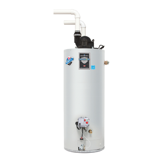
PDV Series
Power Direct Vent Gas Water Heaters
SERVICE
MANUAL
Troubleshooting Guide
and Instructions for Service
(To be performed ONLY by
qualified service providers)
Models Covered
by This Manual:
PDV Series Models:
RG2PDV40S*(N,X)
RG2PDV50S*(N,X)
RG2PDV50H*(N,X)
RG2PDV75H*(N,X)
LG2PDV50H60*(N,X)
LG2PDV75H80*(N,X)
(*) Denotes Warranty Years
Save this manual for future reference
Advertisement
Table of Contents


Need help?
Do you have a question about the LG2PDV50H60N and is the answer not in the manual?
Questions and answers