Summary of Contents for Bradford White RG1PV40SN19
Page 1
PV Series 
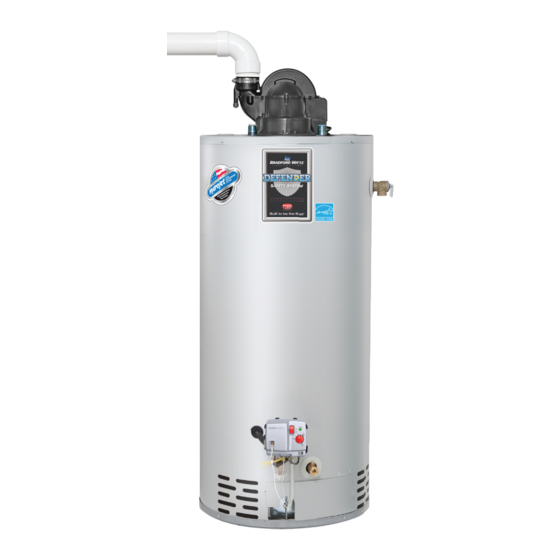
Through-The-Wall (TTW ® Gas Water Heaters - 19 Models SERVICE MANUAL Troubleshooting Guide and Instructions for Service (To be performed ONLY by qualified service providers) Models Covered by This Manual: RG1PV40S*(N,X)19 RG2PV50H*(N,X)19 RG1PV50S*(N,X)19 LG2PV50H*(N,X)19 RG1PV55H*(N,X)19 RG2PV40T*(N,X)19 LG1PV55H*(N,X)19 RG2PV50T*(N,X)19 RG2PV40S*(N,X)19 RG2PV60T*(N,X)19 RG2PV50S*(N,X)19...
The Bradford White PV Series Through-The-Wall Gas Water Heaters Table of Contents Page PV Service Procedure Introduction..........................4 How to Use This Manual ......................5 Tools Required for Service......................5 Specifications ..........................6 Control Timings ........................... 8 Sequence of Operation ........................ 9 Troubleshooting .........................
Page 3
PV Series WARNING: If the information in these instructions is not followed exactly, a fire or explosion may result causing property damage, DANGER personal injury, or death. Do not store or use gasoline or other flammable, combustible, or corrosive vapors and liquids in the vicinity of this or any other appliance.
PV Series Introduction The new Bradford White RG1PV & RG2PV water heaters are designed to provide reliable performance with enhanced standard features. New design features include reliable spark to pilot ignition system, enhanced diagnostics, simplified servicing, quiet operation, additional vent lengths, and Bradford White Defender ®...
It is intended for this manual to be used by qualified service personnel for the primary purpose of troubleshooting and repair of the Bradford White PV Series water heaters. Understanding the sequence of operation section of this manual will contribute greatly to troubleshooting the water heater.
Page 6
PV Series Power Supply Dedicated 115 VAC, 60 Hz, 15A Gas Supply Pipe Minimum 1/2” NPT (schedule 40 black iron pipe recommended) Approved Gas Natural gas, unit must match gas type supplied Type 5.0” W.C. min. for Natural Gas, 11.0” W.C. min. for Propane, Gas Pressure 14.0”...
Page 7
PV Series Vent Tables Venting Specifications for: RG1PV40S, RG2PV40T, RG2PV60T RG1PV50S, RG2PV50T TABLE 1 - VENT CONNECTOR LENGTHS FOR 2 in (5.1 cm) DIAMETER VENT PIPE # of Minimum Maximum Elbows Straight Straight Terminating (excl. vent Length ft Length terminals) ft (m) Elevation of installation 0-10100...
Page 8
PV Series Vent Tables (cont.) Venting Specifications for: RG1PV40S, RG2PV40T, RG2PV60T RG1PV50S, RG2PV50T TABLE 3 – VENT CONNECTOR LENGTHS FOR 4 in (10.1 cm) DIAMETER VENT PIPE Minimum Maximum # of Elbows Terminating (excl. vent Straight Length Straight Length terminals) ft (m) ft (m) 0-10100...
Page 9
PV Series Vent Tables (cont.) Venting Specifications for: RG2PV50H, LG2PV50H RG2PV75H, LG2PV75H RG1PV55H, LG1PV55H TABLE 1 - VENT CONNECTOR LENGTHS FOR 3 in (7.6 cm) DIAMETER VENT PIPE # of Minimum Maximum Elbows Straight Straight Terminating (excl. vent Length Length terminals) ft (m) ft (m)
PV Series Control Timings Ignition State Timing Pre-purge 2 Seconds Trial for Ignition 90 Seconds Flame Stabilization Period 3 Seconds Inter-purge 15 Seconds 1.5 Seconds (2 second maximum; 1 second Flame Failure Response Time minimum.) Post-purge 15 Seconds PS Fault Delay (failed open/close) Retry after 2 minutes Soft Lockout Retry after 5 minutes...
Page 11
PV Series Power Up Sequence 1. Start Up. Upon power up, the control runs a safe-start check with a typical start-up delay of 5 seconds. Flammable Vapor. To assure no outputs are energized if the “Flammable Vapor Sensor” (for RG1PV40S, RG1PV50S, RG2PV40T, RG2PV50T, RG2PV50H) or “Simulated Resistive Device”...
Page 12
PV Series Normal Heating Sequence (cont.) 7. Steady state operation. During steady state operation, the control monitors: Thermostat temperature sensor-when set point temperature is satisfied, gas valve is shut down and blower will post purge for 15 seconds. Control LED flashes a short flash once every 4 seconds (idle) status code.
Page 13
PV Series Abnormal Operation (cont.) times, then 3 times twice with 3 second pauses. The error self clears if the fault clears for at least 15 seconds. c. Water temperature in excess of ECO (energy cut out) limit -The gas control immediately turns off pilot &...
Page 14
PV Series Abnormal Operation (cont.) 5. Flame sensing fault: a. Flame lost during run-the gas control turns off pilot and main valves, runs blower for 15 seconds (inter-purge). The gas control increments the recycle count, if the recycle count has not reached its limit (4), another trial for ignition begins.
Page 15
PV Series Observe green LED indicator on electronic gas control. Error flash codes are displayed with a three second pause before repeating. Check and repair the system as noted in the troubleshooting table below. Service LED Status Control Status Probable Cause Procedure None, control No electrical...
Page 16
PV Series Service LED Status Control Status Probable Cause Procedure 1. Unstable pilot. Failed to light Six-one 2. Pilot tube blocked or restricted. flash, three pilot. Procedure II 3. Oxidation build up on pilot electrode. second System auto 4. Wire damage to pilot assembly or bad pause resets.
Page 17
PV Series Burner Inspection At periodic intervals (every 6 months) a visual inspection should be made of the pilot and main burner for proper operation and to assure no debris is accumulating. Pilot flame should be stable, some causes for an unstable pilot flame are: Water heater vent is less than the allowable vent length.
Page 18
PV Series Burner Cleaning Step 1. Position gas control power switch to the “OFF” position and unplug heater from wall outlet. Step 2. Turn off gas supply to water heater. Step 3. Remove outer jacket door and inner door per service procedure XV on page 41.
Page 19
PV Series Pilot Inspection, Testing and Replacement Step 1. Position gas control power switch to the “OFF” position and unplug heater from wall outlet. Step 2. Turn off gas supply to water heater. Step 3. Remove outer jacket door and inner door per service procedure XV on page 41.
Page 20
PV Series Step 15. To resume operation, follow the instructions located on the lighting instruction label or the lighting instructions located in the installation and operation manual. Pressure Switch Testing WARNING 115-volt potential exposure. Use Step 1. Position power switch on gas caution to avoid personal injury.
PV Series Pressure Switch Replacement WARNING Step 1. Position gas control power 115-volt potential exposure. Use switch to “OFF” position. caution to avoid personal injury. Step 2. Remove the three screws (T20 Torx driver) from control access cover on blower assembly and remove cover (see photo 3).
PV Series Blower Testing WARNING 115-volt potential exposure. Use Step 1. Position gas control caution to avoid personal injury. power switch to “ON” position and adjust control to call for heat. Step 2. Remove the three screws (T20 Torx driver) from control access cover on blower assembly and remove cover (see photo 7).
Page 23
PV Series Blower Removal Step 1. Position gas control power switch to “OFF” position. Unplug blower power cord from Step 2. wall outlet. Disconnect vent system from Step 3. exhaust adapter on top of blower. Remove the three blower mounting Step 4.
Page 24
PV Series Wire Harness Installation External Wire Harness Installation 1. Remove the blower assembly from the heater according to the steps outlined on page 23. 2. On the back of the blower assembly, using a ¾” bit, drill a hole through exterior molded wall. Be very careful not to drill through the interior molded wall.
Page 25
PV Series Wire Harness Installation 6. Install the blower assembly according to the steps outlined on page 21.
PV Series Blower Temperature Switch WARNING WARNING Testing 115-volt potential exposure. Use caution to avoid personal injury. Position power switch on gas control to the “OFF” position. Step 1. Remove the three screws (T20 Torx driver) from control access cover on blower and remove cover (see photo 14).
Page 27
PV Series WARNING Blower Temperature Switch 115-volt potential exposure. Use Replacement caution to avoid personal injury. Step 1. Position gas control power switch to the “OFF” position and unplug heater from wall outlet. Step 2. Remove the three screws (T20 Torx driver) from the control access cover on blower and remove cover (see photo 16).
Page 28
VIII PV Series Line Pressure The gas control is designed for a maximum line pressure of 14.0” W.C. and a minimum line pressure of 1.0” W.C. over the water heater’s rated manifold pressure (check rating plate). Line pressure must be checked with the main burner on and off to assure proper readings.
Page 29
PV Series VIII ECO (Energy Cut Out) The gas control is designed with an ECO device that will reset. To reset the gas control after an error code (4), turn the gas control knob to the “LOW” position and wait a minimum of (5) minutes before relighting following the instructions located on the lighting instruction label or the lighting instructions located in the installation and operation manual.
Page 30
VIII PV Series Gas Control Disassembly/Reassembly (cont.) Step 8. Disconnect temperature sensor from control board. Step 9. To reassemble gas control, follow the previous steps in reverse order. Once gas control is reassembled, burner assembly is reinstalled, and the gas supply line is reconnected, resume water supply to water heater.
Page 31
PV Series VIII Temperature Sensor Testing Using a multi-meter set to the ohms setting, insert one meter probe (see caution) into center wire position of temperature sensor connector, insert the second probe (see caution) into either of the outside wire positions (see photo 19). Alternate the probe on the outside position to the opposite outside wire position (see photo 20).
Page 32
PV Series VIII Determine Water Temperature Inside Tank WARNING Stored water may be HOT WHEN PERFORMING THE FOLLOWING STEPS IN THIS PROCEDURE. Take necessary precaution to prevent personal injury. Note: It is important to understand once the resistance for the temperature sensor is determined, water flow through the heater should not occur.
Page 33
PV Series Gas Control Removal from Water Heater Step 1. Position the gas control power switch to the “OFF” position and unplug heater from wall outlet. Step 2. Drain the heater to a point below the gas control level. Step 3. Turn off the gas supply to the water heater and disconnect gas piping from the gas control.
Page 34
PV Series Reinstallation of inner door assembly. Prior to reinstallation of inner door, fully inspect for the following: -Tears -Other imperfections that will inhibit proper seal -Missing material -Gasket adhesion to inner door -Cracks -Material left on combustion chamber (around opening) -Dirt or debris If the gasket is not affected by any of the above, gasket replacement may not be required.
Page 35
PV Series Flammable Vapor/Simulative Resistance Device Testing Step 1. Position power switch on gas control to the “OFF” position. Step 2. Disconnect flammable vapor sensor from gas control. Step 3. Using a multi-meter set to the ohms setting, check resistance of flammable vapor sensor.
PV Series Safety Circuit Voltage Trace NOTE: This procedure assumes a cool tank. WARNING 115-volt potential exposure. Use caution to avoid personal injury. Remove three screws (T20 Torx screwdriver) from control access cover on blower and remove cover (see photo 20) Position gas control switch on the “ON”...
PV Series 115 VAC Circuit Trace WARNING Step 1. Verify 115 VAC and proper polarity 115 volt potential exposure. Use at wall outlet. caution to avoid personal injury. Step 2. With unit plugged in and control power switch in the “ON” position verify LED status.
PV Series Diptube Inspection & Replacement WARNING Water Heater components and stored water may be HOT when performing the following steps in this procedure. Take necessary precaution to prevent personal injury. Step 1. Position on/off switch of gas control valve to “OFF” position and unplug water heater from wall outlet.
PV Series XIII Anode Inspection & Replacement WARNING Water Heater components and stored water may be HOT when performing the following steps in this procedure. Take necessary precaution to prevent personal injury. Position on/off switch of gas control valve to the “OFF” position and unplug water heater from Step 1.
PV Series DISCONNECT VENT Flue Baffle Inspection and Replacement SYSTEM FROM BLOWER Step 1. Position gas control power switch to the “OFF” position and unplug blower from wall outlet. Step 2. Disconnect vent system from the BLOWER MOUNTING blower. SCREWS Step 3.
Page 41
PV Series Inner Door Removal Procedure Step 1. Position gas control power switch to the “OFF” position. Step 2. Remove outer jacket burner access door. Step 3. Inner Door removal. Remove (2) ¼” hex drive screws from right side inner door. Remove (2) ¼”...
Page 42
PV Series Installation of Inner Door with Gasket Step 7. Clean any residual gasket residue or other debris from combustion chamber surface before installing the inner WARNING door/gasket assembly. Stripped fastener connections Step 8. Place the left side inner door into position first. Firmly may allow for seal breach of position the radiused channel of the inner door around inner door.
Page 43
PV Series Installation of Inner Door with Gasket (cont.) Step 10. Firmly place right side inner door flange against the left side inner door flange and secure with (2) ¼” hex drive screws from step 3b. DO NOT OVER TIGHTEN SCREWS. Step 11.
Page 44
PV Series ® ScreenLok Flame Arrestor Cleaning NOTICE Some models are not equipped with the ® ScreenLok Flame Arrestor. Step 1. Position Gas Control power switch to the “OFF” position. Step 2. Remove outer door. Step 3. Remove outer jacket door and inner door per service procedure XIII on page 39. Step 4.
PV Series Frozen Exhaust Vent Terminal If an exhaust vent terminal is blocked with ice or snow due to severe conditions, the pressure switch and control will not allow the burner to operate. This will result in a three-flash error code. Once the blockage is removed (through melting or other means) the controls will let the burner operate.
Page 46
PV Series 18. Left Side Inner Door 25. Mixing Valve Blower Complete 10. Flue Baffle 19. Screw #10-12 x 3/4 26. Heat Trap Kit Adapter Rubber PVC 11. Heat Trap Insert (Inlet) 20. Drain Valve 27. Gas Valve Pressure Switch Blower 12.
Need help?
Do you have a question about the RG1PV40SN19 and is the answer not in the manual?
Questions and answers