
Related Manuals for Mars Comfort-Aire Century VCD60SA


Summary of Contents for Mars Comfort-Aire Century VCD60SA
- Page 1 Service Manual - VCDxxSA Service Manual VCD-SA Series Air-Handler Air Conditioners Model VCD18, 24, 30, 36, 48, 60 SA Series 517.787.2100 • www.marsdelivers.com...
-
Page 2: Table Of Contents
Service Manual - VCDxxSA Table of Contents Safety Precautions 1. Precautions 2. Information servicing Model Reference & External Appearance 1. Model Reference 2. External Appearance Indoor Unit 1. Indoor Unit - Air Handler Type Outdoor Unit 1. Dimensional Drawings 2. Service Space 3. - Page 3 Service Manual - VCDxxSA Table of Contents Troubleshooting 1. Safety Caution 2. General Troubleshooting 3. Outdoor Unit Point Check Function 4. Information Inquiry 5. Error Diagnosis and Troubleshooting Without Error Code 6. Quick Maintenance by Error Code 7. Troubleshooting by Error Code 8.
- Page 4 Service Manual - VCDxxSA Safety Precautions Contents Precautions ......................2 Information servicing(For flammable materials) ..........3...
-
Page 5: Safety Precautions
Service Manual - VCDxxSA 1. Precautions CAUTION To prevent personal injury, or property or unit damage, • • While unpacking be careful of sharp edges around adhere to all precautionary measures and instructions the unit as well as the edges of the fins on the con- denser and evaporator. -
Page 6: Information Servicing
Service Manual - VCDxxSA 2. Information servicing(For • Prior to work taking place, the area around the equipment is to be surveyed to make sure that there are no flammable flammable materials) hazards or ignition risks. • NO SMOKING signs shall be displayed. Checks to the area Ventilated area •... - Page 7 Service Manual - VCDxxSA • that capacitors are discharged: this shall be done in shall also take into account the effects of aging or a safe manner to avoid possibility of sparking; continual vibration from sources such as compressors or fans. •...
- Page 8 Service Manual - VCDxxSA • The refrigerant charge shall be recovered into the • Before attempting the procedure ensure that: correct recovery cylinders. The system shall be flushed • mechanical handling equipment is available, if with OFN to render the unit safe. This process may required, for handling refrigerant cylinders;...
- Page 9 Service Manual - VCDxxSA • Empty recovery cylinders are evacuated and, if • The recovered refrigerant shall be returned to the possible, cooled before recovery occurs. refrigerant supplier in the correct recovery cylinder, and the relevant Waste Transfer Note arranged. Do not •...
- Page 10 Service Manual - VCDxxSA Model Reference Contents Model Reference ....................2 External Appearance .....................3...
-
Page 11: Model Reference
Service Manual - VCDxxSA 1. Model Reference Refer to the following table to determine the specific indoor and outdoor unit model number of your purchased equipment. Indoor Unit Model Outdoor Unit Model Capacity (Btu/h) Power Supply B-VCD18SA-1 A-VCD18SA-1 B-VCD24SA-1 A-VCD24SA-1 1Ph, 208/230V~, A-VCD30SA-1 B-VCD30SA-1... -
Page 12: External Appearance
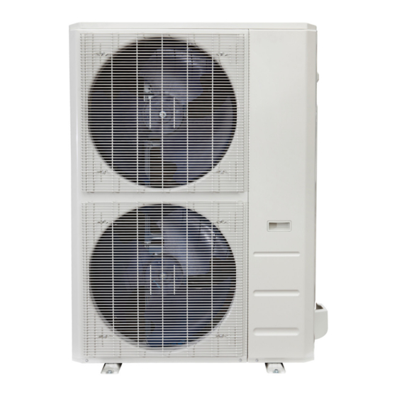
Service Manual - VCDxxSA 2. External Appearance Indoor Unit Air handler Outdoor Unit Single Fan Outdoor Unit Double Fan Outdoor Unit Model Reference ... - Page 13 Service Manual - VCDxxSA Indoor Unit-Air Handler Contents Feature........................2 Dimensional Drawings ..................3 Part names ......................4 Service Place ......................4 Accessories ......................5 Fan Performance ....................6 Noise Criterion Curves ...................9 Electrical Characteristics ..................11 Electrical Wiring Diagrams ..................12...
-
Page 14: Feature
Service Manual - VCDxxSA 1. Feature Full Multi-position installation • This AHU is capable of upflow, downflow, horizontal left, or horizontal right configurations. Installation Convenience • It simplifies the airflow volume adjustment process and saves lots of installation efforts. The traditional adjustment method needs the installers to manually set the motor speed, according to the installation instruction and ducting design. -
Page 15: Dimensional Drawings
Service Manual - VCDxxSA 2. Dimensional Drawings 18/24k 30k/36/48k Dimensions Model inch inch inch Model Height 1143 1245 1346 Model Width 17-1/2 24-1/2 Supply Air Opening Width 15-5/8 19-1/8 22-5/8 Return Air Opening Width 15-1/8 18-5/8 22-1/8 Model Depth Supply Air Opening Depth 10-1/4 10-1/4 10-1/4... -
Page 16: Part Names
Service Manual - VCDxxSA 3. Part names coil compartment (Access panel Removed) Up ow drain pan Horizontal drain pan 4. Service Place MINIMUM CLEARANCE OF 25.4mm/1″ALL SIDES FLEXIBLE DUCT COLLAR IDU-Air Handler 4 ... -
Page 17: Accessories
Service Manual - VCDxxSA 5. Accessories The air conditioning system comes with the following accessories. Use all of the installation parts and accessories to in- stall the air conditioner. Improper installation may result in water leakage, electrical shock and fire, or equipment failure. Name Shape Quantity... -
Page 18: Fan Performance
Service Manual - VCDxxSA 6. Fan Performance 0.148 External static pressure (in.w.c.) 0.1 0.148 0.2 External static pressure (in.w.c. IDU-Air Handler 6 ... - Page 19 Service Manual - VCDxxSA 1000 0.1 0.148 0.2 External static pressure (in.w.c. 1200 1000 0.148 External static pressure (in.w.c.) IDU-Air Handler 7 ...
- Page 20 Service Manual - VCDxxSA 1600 1400 1200 1000 0.148 External static pressure (in.w.c.) 1800 1600 1400 1200 1000 0.148 External static pressure (in.w.c.) IDU-Air Handler 8 ...
-
Page 21: Noise Criterion Curves
Service Manual - VCDxxSA 7. Noise Criterion Curves 1m/3.28ft 2m/6.56ft 1.5m/4.92ft Notes: -Sound measured at 1.5m/4.92ft away from the center of the unit. -Data is valid at free field condition -Data is valid at nominal operation condition -Reference acoustic pressure OdB = 20µPa -Sound level will vary depending on a range of factors such as the construction -(acoustic absorption coefficient) of particular room in which the equipment is installed. - Page 22 Service Manual - VCDxxSA B-VCD30SA-1 B-VCD36SA-1 B-VCD60SA-1 B-VCD48SA-1 IDU-Air Handler 10 ...
-
Page 23: Electrical Characteristics
Service Manual - VCDxxSA 8. Electrical Characteristics Capacity (Btu/h) 18k hyper Heat 24k hyper Heat 30k hyper Heat Phase Power (indoor) Frequency And Volt 208/230V,60Hz Phase Power (Outdoor) Frequency And Volt 208/230V,60Hz Indoor unit(A) Max. Fuse Outdoor unit(A) Indoor unit Line quantity Line diameter(AWG) 16/1.5mm²... -
Page 24: Electrical Wiring Diagrams
Service Manual - VCDxxSA 9. Electrical Wiring Diagrams IDU Capacity (Btu/h) IDU Wiring Diagram 18k~60k 16023000011626 Abbreviation Paraphrase Yellow-Green Conductor Indoor Fan Capacitor Indoor Fan Motor Indoor ECM Motor TO CCM Comm.Bus Central Controller Indoor Room Temperature Sensor Indoor Coil Inlet Temperature Sensor Indoor Coil Outlet Temperature Sensor Indoor Coil Temperature Sensor IDU-Air Handler 12... - Page 25 Service Manual - VCDxxSA...
- Page 26 Service Manual - VCDxxSA 10.1 Micro-Switch Introduce: A For ALARM terminal port CN33 1. Provide the terminal port to connect ALARM, but no voltage of the terminal port , the power from the ALARM system (not from the unit ) 2.
- Page 27 Service Manual - VCDxxSA B. For remote control (ON-OFF) terminal port CN2 and short connector of JR1 1. Remove the short connector of JR1 when you use ON-OFF function; 2. When remote switch off (OPEN); the unit would be off; 3.
- Page 28 Service Manual - VCDxxSA 10.2 Micro-Switch Introduce: FOR SETTING NETADDRESS S1+S2 CODE 0~15 16~31 32~47 48~63 NETADDRESS F A C T O R Y S E T T I N G A. Micro-switch S1 and dial-switch S2 are for address setting when you want to control this unit by a central controller. Range: 00-63 ENC1 CODE...
- Page 29 Service Manual - VCDxxSA The first group controls the electric SW2-1 heating to turn on the temperature 1°C(1.8°F) 2°C(3.6°F) difference Whether the electric heating is SW2-2 delayed Electric auxiliary heating delay start SW2-3 30min 15min time Compressor allowed to Electric heating allowed to Electric heating/compressor allow SW2-4 operate to low limit set by...
- Page 30 Service Manual - VCDxxSA Outdoor Unit Contents Dimensional Drawings ..................2 Service Place ......................7 Capacity Correction Factor for Height Difference ..........8 Noise Criterion Curves ..................14 Refrigerant Cycle Diagrams ................17 Electrical Wiring Diagrams ..................19...
-
Page 31: Dimensional Drawings
Service Manual - VCDxxSA 1. Dimensional Drawings Please check the corresponding dimensional drawing according to the panel plate. ODU Model Panel Plate A-VCD18SA-1 X330 A-VCD24SA-1 X430 A-VCD30SA-1 A-VCD36SA-1 A-VCD48SA-1 A-VCD60SA-1 Outdoor Unit 2 ... - Page 32 Service Manual - VCDxxSA Panel Plate D30 Outdoor Unit 3 ...
- Page 33 Service Manual - VCDxxSA X330(Square grille) Panel Plate Outdoor Unit 4 ...
- Page 34 Service Manual - VCDxxSA X430(Square grille) Panel Plate Outdoor Unit 5 ...
- Page 35 Service Manual - VCDxxSA Panel Plate E30 Outdoor Unit 6 ...
-
Page 36: Service Place
Service Manual - VCDxxSA 2. Service Place Outdoor Unit 7 ... -
Page 37: Capacity Correction Factor For Height Difference
Service Manual - VCDxxSA 3. Capacity Correction Factor for Height Difference Capacity(Btu/h) Pipe Length (m/ft) Cooling 7.5/24.6 10/32.8 20/65.6 30/98.4 20/65.6 0.941 0.919 Indoor Upper 10/32.8 0.974 0.951 0.928 than Outdoor 5/16.4 0.995 0.983 0.960 0.937 Height difference 1.000 0.988 0.965 0.942 H (m) - Page 38 Service Manual - VCDxxSA Capacity Pipe Length (m/ft) (Btu/h) Cooling 7.5/24.6 10/32.8 20/65.6 30/98.4 40/131.2 50/164 25/82 0.917 0.898 0.879 20/65.6 0.946 0.926 0.907 0.887 Indoor Upper than Outdoor 10/32.8 0.975 0.955 0.936 0.916 0.896 5/16.4 0.995 0.985 0.965 0.945 0.925 0.905 1.000...
- Page 39 Service Manual - VCDxxSA Capacity Pipe Length (m/ft) (Btu/h) Cooling 7.5/24.6 10/32.8 20/65.6 30/98.4 40/131.2 50/164 25/82 0.891 0.862 0.832 20/65.6 0.930 0.900 0.871 0.841 Indoor Upper than Outdoor 10/32.8 0.970 0.940 0.910 0.879 0.849 Height 5/16.4 0.995 0.980 0.949 0.919 0.888 0.858...
- Page 40 Service Manual - VCDxxSA Capacity Pipe Length (m/ft) (Btu/h) Cooling 7.5/24.6 15/49.2 25/82 35/114.8 50/164 65/213.3 30/98.4 0.889 0.850 0.812 20/65.6 0.924 0.898 0.859 0.820 Indoor Upper than Outdoor 10/32.8 0.959 0.933 0.907 0.868 0.828 5/16.4 0.995 0.969 0.942 0.916 0.876 0.837 Height...
- Page 41 Service Manual - VCDxxSA Capacity Pipe Length (m/ft) (Btu/h) Cooling 7.5/24.6 15/49.2 25/82 35/114.8 50/164 65/213.3 30/98.4 0.884 0.843 0.802 20/65.6 0.920 0.893 0.852 0.810 Indoor Upper than Outdoor 10/32.8 0.957 0.930 0.902 0.860 0.819 5/16.4 0.995 0.967 0.939 0.911 0.869 0.827 Height...
- Page 42 Service Manual - VCDxxSA Capacity Pipe Length (m/ft) (Btu/h) Cooling 7.5/24.6 15/49.2 25/82 35/114.8 50/164 65/213.3 30/98.4 0.870 0.823 0.775 20/65.6 0.911 0.879 0.831 0.783 Indoor Upper than Outdoor 10/32.8 0.953 0.920 0.888 0.840 0.791 5/16.4 0.995 0.962 0.930 0.897 0.848 0.799 Height...
-
Page 43: Noise Criterion Curves
Service Manual - VCDxxSA 4. Noise Criterion Curves 1.0m/3.28ft Note: H= 0.5 × height of outdoor unit Notes: -Sound measured at 1.0m/3.25ft away from the center of the unit. -Data is valid at free field condition -Data is valid at nominal operation condition -Reference acoustic pressure OdB=20µPa -Sound level will vary depending on arrange off actors such as the construction (acoustic absorption coefficient) of particular room in which the equipment is installed. - Page 44 Service Manual - VCDxxSA A-VCD30SA-1 A-VCD36SA-1 A-VCD48SA-1 A-VCD60SA-1 Outdoor Unit 15 ...
-
Page 45: Refrigerant Cycle Diagrams
Service Manual - VCDxxSA 5. Refrigerant Cycle Diagrams Pipe Size (Diameter:ø) Piping length (m/ft) Elevation (m/ft) mm(inch) Model No. Additional Refrigerant Liquid Rated Max. Rated Max. A-VCD18SA-1 19(3/4) 9.52(3/8) 7.5/24.6 30/98.4 20/65.6 65g/m (0.69oz/ft) Outdoor Unit 16 ... - Page 46 Service Manual - VCDxxSA Pipe Size (Diameter:ø) Piping length (m/ft) Elevation (m/ft) mm(inch) Model No. Additional Refrigerant Liquid Rated Max. Rated Max. A-VCD24SA-1 19(3/4) 9.52(3/8) 7.5/24.6 50/164 25/82 65g/m (0.69oz/ft) A-VCD30SA-1 19(3/4) 9.52(3/8) 7.5/24.6 50/164 25/82 Outdoor Unit 17 ...
- Page 47 Service Manual - VCDxxSA Pipe Size (Diameter:ø) Piping length (m/ft) Elevation (m/ft) mm(inch) Model No. Additional Refrigerant Liquid Rated Max. Rated Max. A-VCD18SA-1 19(3/4) 9.52(3/8) 7.5/24.6 30/98.4 20/65.6 A-VCD24SA-1 19(3/4) 9.52(3/8) 7.5/24.6 50/164 25/82 A-VCD30SA-1 19(3/4) 9.52(3/8) 7.5/24.6 50/164 25/82 65g/m (0.69oz/ft) A-VCD36SA-1 19(3/4)
-
Page 48: Electrical Wiring Diagrams
Service Manual - VCDxxSA 6. Electrical Wiring Diagrams ODU Model ODU Wiring Diagram A-VCD18SA-1 16022000036289 A-VCD24SA-1 16022000036171 A-VCD30SA-1 16022000036170 A-VCD36SA-1 A-VCD48SA-1 16022000036969 A-VCD60SA-1 16022000036169 ODU Main Printed Circuit Inverter Module ODU Model 24V Printed Board Board Printed Board A-VCD18SA-1 17122000046453 17122000054047 A-VCD24SA-1 17122000048064... - Page 49 Service Manual - VCDxxSA Outdoor unit wiring diagram: 16022000036289 WIRING DIAGRAM BLACK (YELLOW) BLUE Pressure Sensor BROWN (RED) Y/GY/G CN 3 CN 4 L-OUT N-OUT BLACK CN1A 24V BOARD OUTDOOR MAIN Pressure Switch :v1Gil � � POWER SUPPLY TO 24V THERMOSTAT L-y--' I UI TO INDOOR UNIT...
- Page 50 Service Manual - VCDxxSA Outdoor unit wiring diagram: 16022000036170 16022000036170 r - - - I OPTIONAL 1- - - T3 T4 TP I OPTIONAL I : OPTIONAL 1 OPTIONAL 1 I TF COMP_TOP EEV : :YEllOI 1 __ YELLOW CN29 CN42 BLACK BLUE...
- Page 51 Service Manual - VCDxxSA...
- Page 52 Service Manual - VCDxxSA...
- Page 53 Service Manual - VCDxxSA...
- Page 54 Service Manual - VCDxxSA Outdoor unit printed circuit board diagram: 17122000044714, 17122000048121,17122000046453...
- Page 55 Service Manual - VCDxxSA Name Meaning Earth: connect to Ground N_in: connect to N-line (208-230V AC input) CN1A L_in: connect to L-line (208-230V AC input) CN16 S: connect to indoor unit communication HEAT1 CN17 connect to compressor heater, 208-230V AC when is ON 4-WAY CN60 connect to 4 way valve, 208-230V AC when is ON.
- Page 56 Service Manual - VCDxxSA Outdoor unit printed circuit board diagram: 17122000048064& 17122000048066 RC 2 VU B...
- Page 57 Service Manual - VCDxxSA Name Meaning Earth: connect to Ground Power Supply N_in: connect to N-line (208-230V AC input) L_in: connect to L-line (208-230V AC input) S: connect to indoor unit communication 4-WAY CN60 connect to 4 way valve, 208-230V AC when is ON. AC-FAN connect to AC fan HEAT2...
- Page 58 Service Manual - VCDxxSA Outdoor unit printed circuit board diagram: 17122000047742...
- Page 59 Service Manual - VCDxxSA Name Meaning CN11 N_in: connect to N-line (208-230V AC input) Power Supply CN12 L_in: connect to L-line (208-230V AC input) EEV-A CN16 EEV-B CN13 EEV-C EEV-D CN15 connect to electric expansion valve EEV-E EEV-F CN17 EEV-G CN14 connect to pipe temp.
- Page 60 Service Manual - VCDxxSA Name Meaning HEAT_D CN20 connect to the heater, 208-230V AC when is ON CN21 HEAT_Y CN36 4-WAY CN38 connect to 4 way valve, 208-230V AC when is ON. CN27 connect to key board CN1 Note: This section is for reference only. Please take practicality as standard.
- Page 61 Service Manual - VCDxxSA Outdoor unit printed circuit board diagram: 17122000037804...
- Page 62 Service Manual - VCDxxSA Name Meaning L1_in: connect to L1-line (230V AC input) Power Supply L2_in: connect to L2-line (230V AC input) Exhaust temp. sensor TP TESTPORT CN35 used for testing HEAT1 CN19/CN20 connect to chassis heater, 208-230V AC when is ON HEAT2 CN24/CN25 connect to compressor heater, 208-230V AC when is ON...
- Page 63 Service Manual - VCDxxSA Outdoor unit IPM board diagram: 17122000042012...
- Page 64 Service Manual - VCDxxSA Name Meaning connect to main board L-Out Power Supply connect to main board N-Out connect to main board CN6 FAN_DC FAN_1/FAN_2 connect to outdoor DC fan 1& DC fan 2 CN_COMP connect to compressor Note: This section is for reference only. Please take practicality as standard.
- Page 65 Service Manual - VCDxxSA Outdoor unit printed circuit board diagram: 17122000054047...
- Page 66 Service Manual - VCDxxSA Name Meaning connect to one-way solenoid valve connect to pressure sensor (5VDC) CN28 connect to electric expansion valve (12VDC) TESTPORT CN45 used for testing (5VDC) connect to suction temp. sensor, cold plate temp. sensor CN11 (5VDC) H-PRO CN38 connect to high pressure switch (5VDC)
- Page 67 Service Manual - VCDxxSA Installation Contents Installation Overview Location Selection Indoor Unit Installation Outdoor Unit Installation Drainage Pipe Installation Refrigerant Pipe Installation Vacuum Drying and Leakage Checking Additional Refrigerant Charge Engineering of Insulation Engineering of Electrical Wiring Test Operation...
-
Page 68: Installation Overview
Service Manual - VCDxxSA 1. Installation Overview Indoor Unit Indoor Unit Install the indoor unit Install the outdoor unit Install the drainpipe Evacuate the refrigeration system Connect the wires Connect the refrigerant pipes Install the panel Perform a test run (only for cassette type) ... -
Page 69: Location Selection
Service Manual - VCDxxSA 2. Location selection 2.1 Unit location selection can refer to installation manual. 2.2 DO NOT install the unit in the following locations: • Where oil drilling or fracking is taking place. • Coastal areas with high salt content in the air. •... -
Page 70: Indoor Unit Installation
Service Manual - VCDxxSA 3. Indoor Unit Installation(AHU) Horizontal installation 3.1 Service space for indoor unit Horizontal installation Plenum Clearances: 24inch(min) MINIMUM CLEARANCE OF 25.4mm/1″ALL SIDES 3.2 Install the main body FLEXIBLE The unit may be installed in one of the upflow, downflow, DUCT COLLAR horizontal left or horizontal right orientations. - Page 71 Service Manual - VCDxxSA For the Horizontal left installation and vertical down installation, the direction of the evaporator should be changed and the drain pan should be removed first. Please do it according to the following steps: 1. Remove the fixed plate of the filter ,then take the filter off.
- Page 72 Service Manual - VCDxxSA 4. Unplug temperature sensors T1,T2,T2A,T2B and electronic expansion valve(EEV) from the control board. T1: Room temperature sensor T2: Evaporator central temperature sensor T2A: Evaporator input temperature sensor(only available for some models) T2B: Evaporator output temperature sensor(only available for some models) 7.
- Page 73 Service Manual - VCDxxSA Cut the foam gasket. Remove knockouts as 11. Reinstall evaporator cover plate. shown in the figure. Hook the wire into the buckle and go down from the wire slot. 12. Connect the wire according to the wiring diagram. Replace foam gaster over wires.
- Page 74 Service Manual - VCDxxSA Installation must be performed by an authorized dealer or specialist. Please make necessary protection when installing the unit. Specification series of electric auxiliary heat module: 5kW,8kW,10kW, 15kw, 20kW,25kW. The electric auxiliary heat module is only used for installation on the AHU internal machine.
- Page 75 Service Manual - VCDxxSA 3. Install the electric auxiliary heating assembly into the chassis shell from the front, and note that the front end needs to be inserted into the shell assembly hole. 4. Tighten the mounting screws. screws 2. Remove the terminal block and power cord, loosen the screws, and remove the electric auxiliary heating cover.
- Page 76 Service Manual - VCDxxSA 9. After installing the electric auxiliary heat module, apply the circuit breaker label near the silicone breaker cover that was just applied. After the electric heating wiring is connected, please confirm before power on: • Check all wiring and ensure reliable connection of wire body.
- Page 77 Service Manual - VCDxxSA Auxiliary Heater Electrical Data CIRCUIT 1 CIRCUIT 2 CIRCUIT 3 Internal Heater part Heater Circuit Heater Heater Heater MOCP MOCP MOCP Protection MCA (1) MCA (1) MCA (1) Amps Amps Amps ECD3K Ckt Bkr 10.8/12.0 14.0/16.0 15.0/20.0 ECD5K Ckt Bkr...
-
Page 78: Outdoor Unit Installation
Service Manual - VCDxxSA 4. Outdoor unit installation 4.3 Install Outdoor Unit Fix the outdoor unit with anchor bolts(M10) 4.1 Service space for outdoor unit >60cm / 23.6” Fix with bolts Caution Since the gravity center of the unit is not at its physical center, so please be careful when lifting it with a sling. - Page 79 Service Manual - VCDxxSA For Vertical drainage pipe (The following table is for 5. Drainage Pipe Installation reference) Install the drainage pipe as shown below and take Reference measures against condensation. Improperly installation Allowable value of inner could lead to leakage and eventually wet furniture and maximum water Remark pipe...
-
Page 80: Drainage Pipe Installation
Service Manual - VCDxxSA 5.3 Insulation work of drainage pipe Refer the introduction to the insulation engineering parts. • The correct installation will not cause converse water flow and the slope of the branch pipes can be adjusted freely • The false installation will cause converse water flow and the slope of the branch pipe can not be ad- justed. -
Page 81: Refrigerant Pipe Installation
Service Manual - VCDxxSA 2.Confirm the cross way of the pipes. 6. Refrigerant Pipe Installation 3.Measure the necessary pipe length. 6.1 Maximum length and drop height 4.Cut the selected pipe with pipe cutter Ensure that the length of the refrigerant pipe, the number •... -
Page 82: Vacuum Drying And Leakage Checking
Service Manual - VCDxxSA 7. Vacuum Drying and Leakage 10. Set the wall conduit Checking 11. Set the supporter for the pipe. 12. Locate the pipe and fix it by supporter 7.1 Purpose of vacuum drying • For horizontal refrigerant pipe, the distance be- •... -
Page 83: Additional Refrigerant Charge
Service Manual - VCDxxSA 4. Rain water might penetrate into pipeline during 8. Additional Refrigerant Charge construction. • After the vacuum drying process is carried out, the additional refrigerant charge process need to be performed. Procedures of special vacuum drying are as follows: •... -
Page 84: Engineering Of Insulation
Service Manual - VCDxxSA 9 . Engineering of Insulation insulation and cause easy aging of the material. 9.2 Insulation of drainage pipe 9.1 Insulation of refrigerant pipe 1. Operational procedure of refrigerant pipe 1. Operational procedure of refrigerant pipe insulation insulation Select the suitable pipe →... - Page 85 Service Manual - VCDxxSA 2. Specific wiring method Engineering of Electrical Wring Connection method A: 1. Highlights of electrical wiring installation Refer to the wiring method of internal and external • All field wiring construction should be finished by machine communication and wired controller as follows: qualified electrician.
- Page 86 Service Manual - VCDxxSA W1/E THERMOSTAT Y1 Y2 B W D W1 W2 INDOOR UNIT OUTDOOR UNIT THERMOSTAT W1 W2 Y1 Y2 B W D S4-1 DIP switch o INDOOR UNIT OUTDOOR UNIT Disconnect and short S4-2 DIP switch o S4-1 DIP switch o circuit to realize heating Perform disconnection and...
- Page 87 Service Manual - VCDxxSA signal of DH changes to 0V, the cooling system starts the dehumidification operation, and the air volume drops to 80% of the nominal cooling air volume. When the partition control, DH is connected to the DH port of the partition controller.
-
Page 88: Test Operation
Service Manual - VCDxxSA 11. Test Operation b. Remove the test cover. Add 2000ml of water to the tank through the attached tube. 1. The test operation must be carried c. Turn on the main power switch and run the air out after the entire installation has been conditioner in COOL mode. - Page 89 Service Manual - VCDxxSA Maintenance Contents First Time Installation Check .................2 Refrigerant Recharge ....................4 Re-Installation .......................5 Indoor Unit ....................5 Outdoor Unit ....................7...
-
Page 90: First Time Installation Check
Service Manual - VCDxxSA 1. First Time Installation Check Air and moisture trapped in the refrigerant system affects To prevent air and moisture from affecting the air the performance of the air conditioner by: conditioner’s performance, the indoor unit, as well as the pipes between the indoor and outdoor unit, must be be •... - Page 91 Service Manual - VCDxxSA Procedure: • If the pressure successfully reaches -0.1 MPa Tighten the flare nuts of the indoor and outdoor (14.5 Psi), fully close the Handle Lo valve, then units, and confirm that both the 2- and 3-way valves cease vacuum pump operations.
-
Page 92: Refrigerant Recharge
Service Manual - VCDxxSA 2. Refrigerant Recharge mA A Procedure: Close both 2- and 3-way valves. 3-way valves. Slightly connect the Handle Lo charge hose to the Operate the air conditioner in cooling mode to charge 3-way service port. the system with liquid refrigerant. Connect the charge hose to the valve at the bottom When the electronic scale displays the correct of the cylinder. -
Page 93: Re-Installation
Service Manual - VCDxxSA 3. Re-Installation Indoor Unit Collecting the refrigerant into the outdoor unit Procedure: Close the 3-way valve so that the gauge rests Confirm that the 2- and 3-way valves are opened. between 0.3 MPa (43.5 Psi) and 0.5 MPa (72.5 Psi). Connect the charge hose with the push pin of Handle Lo to the 3-way valve’s gas service port. - Page 94 Service Manual - VCDxxSA Air purging with vacuum pump Procedure: Tighten the flare nuts of the indoor and outdoor • If the pressure successfully reaches -0.1 MPa (14.5 Psi), fully close the Handle Lo valve, then units, and confirm that both the 2- and 3-way valves cease vacuum pump operations.
-
Page 95: Outdoor Unit
Service Manual - VCDxxSA Outdoor Unit Evacuation for the whole system Procedure: Wait for 5 minutes then check whether the gauge Confirm that the 2- and 3-way valves are opened. needle moves after turning off the vacuum pump. If Connect the vacuum pump to the 3-way valve’s the gauge needle moves backward, check whether service port. - Page 96 Service Manual - VCDxxSA Refrigerant charging mA A Procedure: Close both 2- and 3-way valves. Fully open the Handle Lo manifold valve, 2- and 3-way valves. Slightly connect the Handle Lo charge hose to the 3-way service port. Operate the air conditioner in cooling mode to charge the system with liquid refrigerant.
- Page 97 Service Manual - VCDxxSA Product Features Contents Display Function ....................2 Safety Features ......................3 Basic Functions .......................3 Abbreviation ....................3 Fan Mode ......................3 Cooling Mode ....................3 Heating Mode(Heat Pump Units) ..............4 Auto Mode ....................5 Drying Mode ....................5 Forced Operation Function ................5 Timer Function ....................6 Sleep Function ....................6 3.10 Auto-Restart Function ..................6 Remote Controller Functions ................7...
-
Page 98: Display Function
Service Manual - VCDxxSA 1. Display Function Mode Priority Y/Y2 W W1 W2 E/AUX DH/DS/BK Display Shut down Cooling Cooling 2 Dehumidification 1 Dehumidification 2 Heating 1 Heating 2 Heating 2 Electric heating 1 Electric heating 1 Electric heating 2 Heating 1+Electric heating 1 Heating 1+Electric heating 1 Heating 2 +Electric heating 1... -
Page 99: Safety Features
Service Manual - VCDxxSA 2. Safety Features Fan Mode Compressor three-minute delay at restart When fan mode is activated: • The outdoor fan and compressor are stopped. Compressor functions are delayed for up to ten seconds upon the first startup of the unit, and are delayed for up •... -
Page 100: Heating Mode(Heat Pump Units)
Service Manual - VCDxxSA • Descent curve compressor to cease operations. • When T1-Tsc is lower than or equal to 3.5°C, fan 3.4.2 Indoor Fan Control: speed reduces to high; 1) In heating mode, the indoor fan operates continuously. • When T1-Tsc is lower than or equal to 1°C, fan The fan speed can be set to low, medium, high,turbo speed reduces to medium;... -
Page 101: Auto Mode
Service Manual - VCDxxSA • The unit enters defrosting mode according to the fan-only mode on the basis of ∆T (∆T =T1-TS). temperature value of T3 and T4 as well as the ∆T Running mode compressor running time. ∆T>2°C(3.6°F) Cooling •... -
Page 102: Sleep Function
Service Manual - VCDxxSA preset time. • Timer Off. The machine turns off automatically at the preset time. • Timer On/Off. The machine turns on automatically at the preset On Time, and then turns off automatically at the preset Off Time. •... -
Page 103: Remote Controller Functions
Service Manual - VCDxxSA 4. Remote Controller Functions LCD Wired Remote Controller- KJR-120X/TFBG-E(Standard) i) Buttons and Functions 1. POWER button 6. TIMER button Turn on of turn off the unit. To set timer on and timer off time of one day MODE button 7. - Page 104 Service Manual - VCDxxSA ii) LCD Screen 1 Operation mode indication 8 Sleep mode indication 2 Fan speed indication 9 Electric Auxiliary Heat/Turbo function indication(some models) 3 Temperature display NOTE: AHU models only have turbo functions. 4 Lock indication 10 Left-right swing indication (some models) 5 °C / °F indication 11 Clock display 6 Room temperature indication...
- Page 105 Service Manual - VCDxxSA iii) Installation • Dimensions 20mm 120mm 46mm 60mm 1) Connection • Wire with the indoor unit: 60mm Wiring hole HA HB • 1: Indoor Unit. • 2: Notch the part for the wiring to pass through with a nipper tool. •...
- Page 106 Service Manual - VCDxxSA For some models: The wired controller connects to terminal board, terminal board connects to main control board. Main control board Terminal board CN40 ENC1 HA HB HA HB Wired controller 2) Address setting Unit1 Unit2 Unit16 HA HB HA HB HA HB...
-
Page 107: Centralized Controller
Service Manual - VCDxxSA Centralized Controller 1) Connection For Light commercial air conditioner with XYE port, it can be directly connected to Centralized Controller (CCM03, CCM09). 2) Address setting When setting the address, please make sure the unit is powered off. The address can be set from 0 to 63 by the switch. Turn on the unit, then the address will be effective. - Page 108 Service Manual - VCDxxSA Troubleshooting Contents Safety Caution .......................3 General Troubleshooting ..................4 Outdoor Unit Point Check Function ..............7 Information Inquiry ....................9 Error Diagnosis and Troubleshooting Without Error Code .......13 Remote maintenance ...................13 Field maintenance ..................14 Quick Maintenance by Error Code ..............19 Troubleshooting by Error Code ................21 EH 00 / EC 51 (EEPROM parameter error Diagnosis and Solution) ....21 EL 01 (Indoor and outdoor unit communication error Diagnosis and Solution) 22...
- Page 109 Service Manual - VCDxxSA Troubleshooting Contents 7.13 PC 40(Communication error between outdoor main PCB and IPM board diagnosis and solution) ................36 7.14 PC 08(Current overload protection)/PC 44(Outdoor unit zero speed protection)/ PC 46(Compressor speed has been out of control)/PC 49(Compressor overcurrent failure) diagnosis and solution ...........37 7.15 PC 0F(PFC module protection diagnosis and solution) ........39 7.16 EC 72 (Lack phase failure of outdoor DC fan motor diagnosis and solution) .40...
-
Page 110: Safety Caution
Service Manual - VCDxxSA 1. Safety Caution WARNING Be sure to turn off all power supplies or disconnect all wires to avoid electric shock. While checking indoor/outdoor PCB, please equip oneself with antistatic gloves or wrist strap to avoid damage to the board. WARNING Electricity remains in capacitors even when the power supply is off. -
Page 111: General Troubleshooting
Service Manual - VCDxxSA 2. General Troubleshooting Error Display (Indoor Unit) When the indoor unit encounters a recognized error, the operation lamp will flash in a corresponding series, the timer lamp may turn on or begin flashing, and an error code will be displayed. These error codes are described in the following table: Display Error Information... - Page 112 Service Manual - VCDxxSA PC 03 Low pressure protection (for some models) TS33 Outdoor unit malfunction TS35 ec 0 PC 0L Low ambient temperature protection TS42 Mismatch between the new and old platforms TS48 FL 09 For other errors: The display board may show a garbled code or a code undefined by the service manual. Ensure that this code is not a temperature reading.
- Page 113 Service Manual - VCDxxSA Error Display (For Some Outdoor Unit) Display Malfunction or Protection Solution Outdoor EEPROM malfunction TS21 EC 51 Indoor / outdoor units communication error TS22 EL 01 Communication malfunction between adapter board and outdoor main board TS48 EL 16 PC 00 IPM module protection...
-
Page 114: Outdoor Unit Point Check Function
Service Manual - VCDxxSA 3. Outdoor Unit Point Check Function • A check switch is included on the outdoor PCB. • Push SW1 to check the unit’s status while running. The digital display shows the following codes each time the SW1 is pushed. - Page 115 Service Manual - VCDxxSA Frequency limit caused by The display value is Bit7 IGBT radiator a hex number. For example, the digital Bit6 Reserved display show 2A, then Bit5 Reserved Bit5=1, Bit3=1, and Frequency limit caused by low Bit4 Bit1=1. temperature of T2.(LH00) Frequency limit caused by Frequency limit symbol...
-
Page 116: Information Inquiry
Service Manual - VCDxxSA 4. Information Inquiry • To enter engineer mode, in power-on or standby mode, and in non-locked state, press the key combination “ON/OFF + Air Speed” for 7s: • After entering the engineer mode, the remote control will display icons of “Auto, Cool, Dry, Heat”, and the Battery icon;... - Page 117 Service Manual - VCDxxSA press "On/Off" for 2s to enter Twins Selector, the code displayed is “Ch”, Compressor press "OK" to send the Query Twins Selector code; press the Up/Down key to Running select, 0 indicates that there is no Twins, 1 indicates the host, and 2 indicates Frequency Fr the slave.
- Page 118 Service Manual - VCDxxSA press "On/Off" for 2s to enter the Cooling Temperature Compensation Value Settings, the code displayed is “Ch”, then press "OK" to send the Query Cooling Temperature Compensation Value code; press the Up/Down key to select the cooling temperature compensation value, then press "OK"; and press "On/Off"...
- Page 119 Service Manual - VCDxxSA Error code of engineer mode Display Error Information Indoor unit EEPROM parameter error EH 00 Indoor / outdoor unit communication error EL 01 Communication malfunction between adapter board and outdoor main board EL 16 The indoor fan speed is operating outside of the normal range EH 03 Outdoor unit EEPROM parameter error EC 51...
-
Page 120: Error Diagnosis And Troubleshooting Without Error Code
Service Manual - VCDxxSA 5. Error Diagnosis and Troubleshooting Without Error Code WARNING Be sure to turn off unit before any maintenance to prevent damage or injury. Remote maintenance SUGGESTION: When troubles occur, please check the following points with customers before field maintenance. Problem Solution Unit will not start... -
Page 121: Field Maintenance
Service Manual - VCDxxSA Field maintenance Problem Solution Unit will not start TS17 - TS18 Compressor will not start but fans run TS17 - TS18 Compressor and condenser (outdoor) fan will not start TS17 - TS18 Evaporator (indoor) fan will not start TS17 - TS18 Condenser (Outdoor) fan will not start TS17 - TS18... - Page 122 Service Manual - VCDxxSA Troubleshooting 15 ...
- Page 123 Service Manual - VCDxxSA 1.Remote Maintenance Others Possible causes of trouble Unit will not start The power switch is on but fans will not start ☆ The temperature on the display board cannot be set Unit is on but the wind is not cold(hot) Unit runs, but shortly stops The unit starts up and stops frequently ☆...
- Page 124 Service Manual - VCDxxSA 2.Field Maintenance Refrigerant Circuit Others Possible causes of trouble Unit will not start Compressor will not start but fans run ☆ Compressor and condenser (outdoor) fan will not start Evaporator (indoor) fan will not start Condenser (Outdoor) fan will not start Unit runs, but shortly stops ☆...
- Page 125 Service Manual - VCDxxSA 2.Field Maintenance Electrical Circuit Possible causes of trouble Unit will not start ☆ ☆ ☆ ☆ ☆ ☆ Compressor will not start but fans run ☆ ☆ ☆ ☆ ☆ Compressor and condenser (outdoor) fan will not start ☆...
-
Page 126: Quick Maintenance By Error Code
Service Manual - VCDxxSA 6. Quick Maintenance by Error Code If you do not have the time to test which specific parts are faulty, you can directly change the required parts according the error code. You can find the parts to replace by error code in the following table. Error Code Part requiring replacement... - Page 127 Service Manual - VCDxxSA Part requiring EL 16 eh 0b pc 06 pc 08/44/ 49 pc 0a pc 0f replacement Indoor PCB Outdoor PCB Outdoor fan motor T3 Sensor TP Sensor Pressure sensor Reactor Compressor IPM module board Data adapter board High pressure valve assy High pressure protector Low pressure protector...
-
Page 128: Troubleshooting By Error Code
Service Manual - VCDxxSA 7. Troubleshooting by Error Code EH 00 / EC 51 (EEPROM Parameter Error Diagnosis and Solution) Description: Indoor or outdoor PCB main chip does not receive feedback from EEPROM chip. Recommended parts to prepare: • Indoor PCB •... -
Page 129: El 01 (Indoor And Outdoor Unit Communication Error Diagnosis And Solution)
Service Manual - VCDxxSA EL 01 (Indoor and Outdoor Unit Communication Error Diagnosis and Solution) Description: Indoor unit can not communicate with outdoor unit Recommended parts to prepare: • Signal wires • Magnet ring • Indoor PCB • Outdoor PCB Troubleshooting and repair: XYE Communication: Power off, then restart the unit 2... - Page 130 Service Manual - VCDxxSA S Communication: Power off, then restart the unit after 2 minutes. Does the error code Solved disappear? Check the wiring connection Correct the connection or between indoor and outdoor change wires unit, are they good? The value is alternative from negative to positive Check the wiring connection Measure the DC voltage between N/L2...
- Page 131 Service Manual - VCDxxSA Remarks: • Use a multimeter to test the DC voltage between 2 port(or S or L2 port) and 3 port(or N or S port) of outdoor unit. The red pin of multimeter connects with 2 port(or S or L2 port) while the black pin is for 3 port(or N or S port) . •...
-
Page 132: Eh 03 / Ec 07 (Fan Speed Is Operating Outside Of The Normal Range )/Ec
Service Manual - VCDxxSA EH 03 / EC 07 (Fan Speed Is Operating Outside of Normal Range)/EC 71(Over Current Failure of Outdoor DC Fan Motor)/ EC73(Zero-speed failure of outdoor DC fan motor) Diagnosis and Solution Description: When indoor / outdoor fan speed keeps too low or too high for a certain time, the unit ceases operation and the LED displays the failure. - Page 133 Service Manual - VCDxxSA Index: 1. Indoor DC Fan Motor(control chip is in fan motor) Power on and when the unit is in standby, measure the voltage of pin1&pin2 of CN15, pin3 of CN34 in fan motor connector. If the value of the voltage is not in the range showing in below table, the PCB must has problems and need to be replaced.
-
Page 134: Eh 60/Eh 61/Ec 53/Ec 52/Ec 54/Ec 56/Ec 57/Ec 50/Ec 5C
Service Manual - VCDxxSA EH 60/EH 61/EH 62/ EH 65/ EC 53/EC 52/EC 54/EC 56/EC 57/EC 50/EC 5C (Open Circuit or Short Circuit of Temperature Sensor Diagnosis and Solution) Description: If the sampling voltage is lower than 0.06V or higher than 4.94V, the LED displays the failure. Recommended parts to prepare: •... -
Page 135: El 0C (Refrigerant Leakage Detection Diagnosis And Solution)
Service Manual - VCDxxSA EL 0C (Refrigerant Leakage Detection Diagnosis and Solution) Description: Judging the abnormality of the refrigeration system according to the number of compressor stops and the changes in operating parameters caused by excessive exhaust temperature. Recommended parts to prepare: •... -
Page 136: Eh 0E(Water-Level Alarm Malfunction Diagnosis And Solution)
Service Manual - VCDxxSA EH 0E(Water-Level Alarm Malfunction Diagnosis and Solution) Description: If the sampling voltage is not 5V, the LED displays the failure code. Recommended parts to prepare: • Connection wires • Water-level switch • Indoor PCB Power off, then restart the unit 2 minutes later. -
Page 137: Pc 00(Ipm Malfunction Or Igbt Over-Strong Current Protection Diagnosis And Solution)
Service Manual - VCDxxSA PC 00(IPM malfunction or IGBT over-strong current protection Diagnosis and Solution) Description: When the voltage signal the IPM sends to the compressor drive chip is abnormal, the display LED shows “PC 00” and the AC turn off. Recommended parts to prepare: •... -
Page 138: Pc 01(Over Voltage Or Too Low Voltage Protection)/Pc
Service Manual - VCDxxSA PC 01(Over voltage or too low voltage protection)/PC 10(Outdoor unit low AC voltage protection)/PC 11(Outdoor unit main control board DC bus high voltage protection)/PC 12(Outdoor unit main control board DC bus high voltage protection /341 MCE error) Diagnosis and Solution Description: Abnormal increases or decreases in voltage are detected by checking the specified voltage detection circuit. -
Page 139: Pc 04(Inverter Compressor Drive Error Diagnosis And Solution)
Service Manual - VCDxxSA PC 04(Inverter compressor drive error Diagnosis and Solution) Description: An abnormal inverter compressor drive is detected by a special detection circuit, including communication signal detection, voltage detection, compressor rotation speed signal detection and so on. Recommended parts to prepare: •... -
Page 140: Pc 03/Pc 31(Low Pressure Protection Diagnosis And Solution)
Service Manual - VCDxxSA 7.10 PC 03/PC 31(Low Pressure Protection Diagnosis and Solution) Description: If the sampling voltage is not 5V, the LED displays a failure code. Recommended parts to prepare: • Connection wires • Low pressure protector • Indoor fan assembly •... -
Page 141: Protection Of Ipm Module Diagnosis And Solution)
Service Manual - VCDxxSA 7.11 PC 02/LC 06(Top temperature protection of compressor or High temperature protection of IPM module diagnosis and solution) Description: For some models with overload protection, If the sampling voltage is not 5V, the LED will display the failure. If the temperature of IPM module is higher than a certain value, the LED displays the failure code. -
Page 142: Ec 0D(Outdoor Unit Malfunction Diagnosis And Solution)
Service Manual - VCDxxSA Check the fastening screws on the PCB and IPM radiator. Replace the outdoor Are they fixed tightly? control PCB. Tighten the screws and apply silicon grease. 7.12 EC 0d(Outdoor unit malfunction Diagnosis and Solution) Description: The indoor unit detect the outdoor unit is error. Recommended parts to prepare: •... -
Page 143: Pc 40(Communication Error Between Outdoor Main Pcb And Ipm Board Diagnosis And Solution)
Service Manual - VCDxxSA 7.13 PC 40(Communication error between outdoor main PCB and IPM board diagnosis and solution) Description: The main PCB cannot detect the IPM board. Recommended parts to prepare: • Connection wires • IPM board • Outdoor main PCB •... -
Page 144: Pc 08(Current Overload Protection)/Pc 44(Outdoor Unit Zero Speed Protection)
Service Manual - VCDxxSA 7.14 PC 08(Current overload protection)/PC 44(Outdoor unit zero speed protection)/ PC 46(Compressor speed has been out of control)/PC 49(Compressor overcurrent failure) diagnosis and solution Description: An abnormal current rise is detected by checking the specified current detection circuit. Recommended parts to prepare: •... - Page 145 Service Manual - VCDxxSA Was the protection activated in standby? Is the power voltage is Restart the unit when the power normal? supply returns to normal Is outdoor terminal voltage Is the power wiring Reconnect the normal? wired correctly? power wiring Is the voltage between L and Are L and N wired Reconnect L and N...
-
Page 146: Pc 0F(Pfc Module Protection Diagnosis And Solution)
Service Manual - VCDxxSA 7.15 PC 0F PFC module protection diagnosis and solution) Description: When the voltage signal that IPM send to compressor drive chip is abnormal, the LED displays the failure code and the AC turns off. Recommended parts to prepare: •... -
Page 147: Ec 72 (Lack Phase Failure Of Outdoor Dc Fan Motor Diagnosis And Solution)
Service Manual - VCDxxSA 7.16 EC 72 (Lack phase failure of outdoor DC fan motor diagnosis and solution) Description: When the three-phase sampling current of the DC motor is abnormal, especially when the current of one or more phases is always small and almost 0, the LED displays the failure code. Recommended parts to prepare: •... -
Page 148: Pc 43 (Outdoor Compressor Lack Phase Protection Diagnosis And Solution)
Service Manual - VCDxxSA 7.17 PC 43 (Outdoor compressor lack phase protection diagnosis and solution) Description: When the three-phase sampling current of the compressor is abnormal, especially when the current of one or more phases is always small and almost 0, the LED displays the failure code Recommended parts to prepare: •... -
Page 149: Pc 45 (Outdoor Unit Ir Chip Drive Failure Diagnosis And Solution)
Service Manual - VCDxxSA 7.18 PC 45 (Outdoor unit IR chip drive failure) diagnosis and solution Description: When the IR chip detects its own parameter error, the LED displays the failure code when power on. Recommended parts to prepare: • Inverter module PCB. Troubleshooting and repair: Power off,then restart the unit 2 minutes later. -
Page 150: Ec55 (Outdoor Ipm Module Temperature Sensor Fault) Diagnosis And Solution
Service Manual - VCDxxSA 7.20 EC55 (Outdoor IPM module temperature sensor fault) diagnosis and solution Description: If the sampling voltage is 0V or 5V, the LED displays the failure code. Recommended parts to prepare: • IPM module PCB • Connection wires •... -
Page 151: Pc 30 (High Pressure Protection Diagnosis And Solution)
Service Manual - VCDxxSA 7.21 PC 30 (High pressure protection diagnosis and solution) Description: Outdoor pressure switch cut off the system because high pressure is higher than 4.4 MPa Recommended parts to prepare: • Connection wires • Pressure switch • Outdoor fan •... - Page 152 Service Manual - VCDxxSA High pressure protection High pressure protection Are the high pressure switch Are the high pressure switch Connect high pressure switch and Connect high pressure switch and and main control boar wired and main control boar wired mian control board mian control board correctly?
-
Page 153: Pc 0A (High Temperature Protection Of Condenser Diagnosis And Solution)
Service Manual - VCDxxSA 7.22 PC 0A (High temperature protection of condenser diagnosis and solution) Description: When the outdoor pipe temperature is more than 65°C, the unit stops. It starts again only when the outdoor pipe temperature is less than 52°C. Recommended parts to prepare: •... -
Page 154: Pc 06 (Discharge Temperature Protection Of Compressor Diagnosis And Solution)
Service Manual - VCDxxSA 7.23 PC 06 (Discharge temperature protection of compressor diagnosis and solution) Description: If the compressor discharge temperature exceeds a certain level for nine seconds, the compressor ceases operation, the LED displays the failure code Recommended parts to prepare: •... -
Page 155: Eh 0B(Communication Error Between Indoor Two Chips Diagnosis And Solution)
Service Manual - VCDxxSA 7.24 EH 0b(Communication error between indoor two chips diagnosis and solution) Description: Indoor PCB main chip does not receive feedback from another chip. Recommended parts to prepare: • Indoor main board • Adapter board Troubleshooting and repair: Shut off the power supply and turn it on 2 minutes later. -
Page 156: El 16(Communication Malfunction Between Adapter Board And Outdoor Main Board Diagnosis And Solution)
Service Manual - VCDxxSA 7.25 EL 16(Communication malfunction between adapter board and outdoor main board diagnosis and solution) Description: The adapter PCB cannot detect the main control board. Recommended parts to prepare: • Connection wires • Adapter board • Outdoor main PCB Troubleshooting and repair: Power off, then restart the unit after 3 minutes. -
Page 157: Pc 41(Outdoor Compressor Current Sampling Circuit Failure Diagnosis And Solution)
Service Manual - VCDxxSA 7.27 PC 41(Outdoor compressor current sampling circuit failure diagnosis and solution) Description: Three-phase sampling offset voltage error, the static bias voltage is normally 2.5V Recommended parts to prepare: • Outdoor main PCB Troubleshooting and repair: Shut off the power supply and turn it on 2 minutes later. -
Page 158: Check Procedures
Service Manual - VCDxxSA 8. Check Procedures 8.1 Temperature Sensor Check WARNING Be sure to turn off all power supplies or disconnect all wires to avoid electric shock. Operate after compressor and coil have returned to normal temperature in case of injury. 1. - Page 159 Service Manual - VCDxxSA Resistance Value ASM135D23UFZ ATM115D43UFZ2 ASN98D22UFZ ATQ360D1UMU Blue-Red Blue-Black 1.75Ω 1.87Ω 1.57Ω 0.37Ω Red-Black ATF235D22UMT Resistance Value ATF250D22UMT ATF310D43UMT KSK103D33UEZ3 ASM98D32UFZ KTF250D22UMT Blue-Red Blue-Black 0.75Ω 0.65Ω 2.13Ω 2.2Ω Red-Black ASN140D21UFZ Resistance Value ASK89D29UEZD KTM240D57UMT KSN140D58UFZ KSN140D21UFZ Blue-Red Blue-Black 1.28Ω...
- Page 160 Service Manual - VCDxxSA KTQ420D1UMU ATN150D30UFZA ATQ420D1SN5A1 Resistance Value KTF310D43UMT KTM240D46UKT2 KTM240D43UKT EAPQ420D1UMUA EAPQ440D1UMUA Blue-Red Ω Blue-Black 0.65Ω 1.03Ω 1.04Ω 0.37Ω Red-Black Note: The picture and the value are only for reference, actual condition and specific value may vary. 8.3 IPM Continuity Check WARNING Electricity remains in capacitors even when the power supply is off.
- Page 161 Service Manual - VCDxxSA Digital tester Resistance value Digital tester Resistance value (+)Red (-)Black (+)Red (-)Black ∞ ∞ (Several MΩ) (Several MΩ) Note: The picture and the value are only for reference, actual condition and specific value may vary. Normal voltage of P and N 208-240V(1-phase,3-phase) 380-415V(3-phase) In standby...
- Page 162 Service Manual - VCDxxSA 8.4 4-way Valve Check 1. Power on, use a digital tester to measure the voltage, when the unit operates in cooling, it is 0V. When the unit operates in heating, it is about 230VAC. If the value of the voltage is not in the range, the PCB must have problems and need to be replaced. 2 Turn off the power, use a digital tester to measure the resistance.
- Page 163 Service Manual - VCDxxSA 8.5 EEV Check WARNING Electricity remains in capacitors even when the power supply is off. Ensure the capacitors are fully discharged before troubleshooting. 1. Disconnect the connector from outdoor PCB. 2. Measure the resistance value of each winding using a multi-meter. 3.
- Page 164 Service Manual - VCDxxSA Indoor Unit Disassembly-Air Handler Contents Indoor Unit Disassembly ..................1 Electrical Parts ....................2 Fan Motor and Fan ..................5 Evaporator .....................7 Electric Auxiliary Heat Module (Optional) ............9...
- Page 165 Service Manual - VCDxxSA 1. Indoor Unit Disassembly Electrical Parts (Antistatic gloves must be worn.) Procedure Illustration 1) Remove 2 screws of the upper cover Plate assembly and then remove the it. (see CJ_AHU_001) CJ_AHU_001 2) Remove 2 screws and unplug the plugs. (see CJ_AHU_002) 3) Pull out the electric control box subassembly.(see CJ_AHU_002)
- Page 166 Service Manual - VCDxxSA Procedure Illustration 4) Release 2 fixing screws and 1earthing screw.(see CJ_AHU_003) 5) Unplug the plugs and then remove the main control board subassembly. (see CJ_AHU_003) CJ_AHU_003 6) Release 1 fixing screw of the data transfer module control board to remove it.
- Page 167 Service Manual - VCDxxSA Procedure Illustration 7) Release 2 screws and then remove the transformer. (see CJ_AHU_005) CJ_AHU_005 Note: This section is for reference only. Actual unit appearance may vary. Indoor Unit Disassembly 4 ...
- Page 168 Service Manual - VCDxxSA Fan Motor and Fan Procedure Illustration 1) Remove 2 screws of fan assembly (see CJ_AHU_006) CJ_AHU_006 2) Take out the fan assembly (see CJ_ AHU_007) CJ_AHU_007 Note: This section is for reference only. Actual unit appearance may vary. ...
- Page 169 Service Manual - VCDxxSA Procedure Illustration 3) Release 3 nuts fixing the fan motor and then take out the fan motor. (see CJ_AHU_008) CJ_AHU_008 4) Release the 1 nut fixing the fan and then take out the fan. (see CJ_AHU_009) CJ_AHU_009 Note: This section is for reference only.
- Page 170 Service Manual - VCDxxSA Evaporator Procedure Illustration 1) Remove the cover plate (see CJ_ AHU_010) CJ_AHU_010 2) Remove 3 screws of cover plate assembly(below) (see CJ_AHU_011) CJ_AHU_011 Note: This section is for reference only. Actual unit appearance may vary. Indoor Unit Disassembly 7 ...
- Page 171 Service Manual - VCDxxSA Procedure Illustration 3) Take out the evaporator(with water collector assembly). (see CJ_AHU_012) CJ_AHU_012 4) Remove 2 screws of water collector assembly.(see CJ_AHU_013) 4) Release evaporator and the water collector assembly. CJ_AHU_013 Note: This section is for reference only. Actual unit appearance may vary. ...
- Page 172 Service Manual - VCDxxSA Electric Auxiliary Heat Module (Optional) Procedure Illustration 1) Remove 2 screws of the upper cover Plate assembly and then remove the it. (see CJ_AHU_001) CJ_AHU_001 screws 2) Remove 3 fixing screws. (see CJ_ AHU_014) CJ_AHU_014 Note: This section is for reference only. Actual unit appearance may vary. ...
- Page 173 Service Manual - VCDxxSA Procedure Illustration 3) Pull out the auxiliary heat module. (see CJ_AHU_015) CJ_AHU_015 4) Pull out the wire connect to the fuse with needle-nose pliers(see CJ_ AHU_016) Note: Qty of EAH-03B&EAH-05B is 1, Qty of EAH-08B&EAH-10B is 2, Qty of EAH-15B is 3, Qty of EAH-20B is 4, Qty of EAH-25B is 5.
- Page 174 Service Manual - VCDxxSA Outdoor Unit Disassembly Contents Outdoor Unit Table ....................2 Outdoor Unit Disassembly ..................3 Panel Plate .....................3 Electrical Parts .....................16 Fan Assembly ....................40 Fan Motor ....................41 Sound Blanket .....................42 Four-way Valve ....................43 Compressor ....................44...
-
Page 175: Outdoor Unit Table
Service Manual - VCDxxSA 1. Outdoor Unit Disassembly Outdoor Unit Table Outdoor Unit Model Panel Plate PCB Board A-VCD18SA-1 X330 PCB Board 11 A-VCD24SA-1 X430 PCB Board 3 A-VC30SA-1 PCB Board 14 A-VCD36SA-1 PCB Board 14 A-VCD48SA-1 PCB Board 8 A-VCD60SA-1 PCB Board 8 ... -
Page 176: Panel Plate
Service Manual - VCDxxSA 2. Outdoor Unit Disassembly 2.1 Panel Plate 1. . X230/X3 Procedure Illustration 1) Turn off the air conditioner and the power breaker. 2) Remove the screw of the big handle and then remove the big handle (1 screws) (see CJ_X230_001). - Page 177 Service Manual - VCDxxSA Procedure Illustration 4) Remove the screws of water collecting cover and then remove the water collecting cover (2 screws) (see CJ_ X230_003). Water Collecting Cover CJ_X230_003 5) Remove the screws of the front panel and then remove the front panel (7 screws(onoff models) or 9 screws(inverter models) (see CJ_ X230_004).
- Page 178 Service Manual - VCDxxSA Procedure Illustration 6) Remove the screws of the right panel and then remove the right panel (5 screws) (see CJ_X230_005). Right Panel CJ_X230_005 Note: This section is for reference only. Actual unit appearance may vary. Outdoor Unit Disassembly 5 ...
- Page 179 Service Manual - VCDxxSA 2.X430 Procedure Illustration 1) Turn off the air conditioner and the power breaker. 2) Remove the screw of the big handle and then remove the big handle (1 screw) (see CJ_X430_001). Big Handle CJ_X430_001 Top Cover 3) Remove the screws of the top cover and then remove the top cover (3 screws).
- Page 180 Service Manual - VCDxxSA Procedure Illustration 4) Remove the screws of water collecting cover and then remove the water collecting cover (2 screws) (see CJ_ X430_003). Water Collecting Cover CJ_X430_003 5) Remove the screws of the front panel and then remove the front panel (7 screws(onoff models) or 9 screws(inverter models) (see CJ_ X430_004).
- Page 181 Service Manual - VCDxxSA Procedure Illustration 6) Remove the screws of the right panel and then remove the right panel (6 screws) (see CJ_X430_005). Right Panel CJ_X430_005 Note: This section is for reference only. Actual unit appearance may vary. Outdoor Unit Disassembly 8 ...
- Page 182 Service Manual - VCDxxSA 3. D30 Procedure Illustration 1) Turn off the air conditioner and the Big Handle power breaker. 2) Remove the screws of the big handle and then remove the big handle (2 screws) (see CJ_D30_001). CJ_D30_001 3) Remove the screws of the top cover and then remove the top cover (4 Top Cover screws).
- Page 183 Service Manual - VCDxxSA Procedure Illustration 4) Remove the screws of the front right panel and then remove the front right panel (2 screws) (see CJ_D30_003). Front Right Panel CJ_D30_003 5) Remove the screws of the front panel and then remove the front panel (9 screws) (see CJ_D30_004).
- Page 184 Service Manual - VCDxxSA Procedure Illustration 6) Remove the screws of water collecting cover and then remove the water collecting cover (2 screws) (see CJ_ D30_005). Water Collecting Cover CJ_D30_005 7) Remove the screws of the rear net and then remove the rear net (2 screws) (see CJ_D30_006).
- Page 185 Service Manual - VCDxxSA Procedure Illustration 8) Remove the screws of the right panel and then remove the right panel (8 screws) (see CJ_D30_007). Right Panel CJ_D30_007 Note: This section is for reference only. Actual unit appearance may vary. Outdoor Unit Disassembly 12 ...
- Page 186 Service Manual - VCDxxSA 4. E30/590 Procedure Illustration 1) Turn off the air conditioner and the power breaker. 2) Remove the screws of the big handle and then remove the big handle (2 screws) (see CJ_E30_001). CJ_E30_001 3) Remove the screws of the top cover and then remove the top cover (4 screws).
- Page 187 Service Manual - VCDxxSA Procedure Illustration 5) Remove the screws of the front right panel and then remove the front right panel (2 screws) (see CJ_E30_004). CJ_E30_004 Note: This section is for reference only. Actual unit appearance may vary. Outdoor Unit Disassembly 14 ...
- Page 188 Service Manual - VCDxxSA Procedure Illustration 1) Remove the screws of the front panel and then remove the front panel (7 screws) (see CJ_E30_005). CJ_E30_005 2) Remove the screws of the right panel and then remove the right panel (10 screws) (see CJ_E30_006). CJ_E30_006 Note: This section is for reference only.
-
Page 189: Electrical Parts
Service Manual - VCDxxSA Electrical parts Antistatic gloves must be worn when you disassemble the electronic box. WARNING: Note: Remove the air outlet grille(refer to 3.1 Panel Plate) before disassembling electrical parts. 1. PCB board 1 Procedure Illustration 1) Remove the screws of the top cover. (2 screws) (see CJ_ODU_PCB_001- 1 ). - Page 190 Service Manual - VCDxxSA 2. PCB board 2 Procedure Illustration 1) Unfix the hooks and then open the electronic control box cover (4 hooks) (see CJ_ODU_PCB_002-1 ). 4-Way Valve 2) Disconnect the connector for fan CJ_ODU_PCB_002-1 motor from the electronic control board (see CJ_ODU_PCB_002-2 ).
- Page 191 Service Manual - VCDxxSA 3. PCB board 3 Procedure Illustration 1) Remove the screws and unfix the hooks, then open the electronic control box cover (5 screws and 2 hooks )(see CJ_ODU_PCB_003-1 ). Note:Electric control box cover cannot be removed, so the voltage between P and N cannot be measured.
- Page 192 Service Manual - VCDxxSA 4. PCB board 4 Procedure Illustration 1) Remove the screws of the top cover. (1 screws) (see CJ_ODU_PCB_004- 1 ). CJ_ODU_PCB_004-1 2) Unfix the hooks and then open the electronic control box cover (5 hooks) (see CJ_ODU_PCB_004-2 ). CJ_ODU_PCB_004-2 3) Disconnect the connector for fan motor from the IPM board (see CJ_...
- Page 193 Service Manual - VCDxxSA Procedure Illustration 5) Pull out the wire connected with the terminal. (see CJ_ODU_PCB_004-4 ). T3/T4 6) Pull out connectors of the condenser coil temp. sensor(T3),outdoor ambient temp. sensor(T4) and discharge temp. sensor(TP) (see CJ_ODU_PCB_004-4 ). 7) Disconnect the electronic expansion valve wire (see Fig CJ_ODU_PCB_004- 4 ).
- Page 194 Service Manual - VCDxxSA 5. PCB board 5 Procedure Illustration 1) Unfix the hooks and then open the electronic control box cover (4 hooks) (see CJ_ODU_PCB_005-1 ). 2) Disconnect the connector for outdoor DC fan from the electronic control board (see CJ_ODU_ PCB_005-2 ).
- Page 195 Service Manual - VCDxxSA 6. PCB board 6 Procedure Illustration 1) Unfix the hooks and then open the electronic control box cover (4 hooks) (see CJ_ODU_PCB_006-1 ). CJ_ODU_PCB_006-1 2) Remove 8 screws on the electronic control board and then turn over the electronic control board (see CJ_ODU_PCB_006-2 ).
- Page 196 Service Manual - VCDxxSA Procedure Illustration 3) Pull out the two blue wires connected with the four way valve. connect to IPM board PFC Inductor (see CJ_ODU_PCB_006-3 )(for heat T3&T4 Compressor pump models) 4) Pull out connectors of the condenser coil temp.
- Page 197 Service Manual - VCDxxSA 7. PCB board 7 Procedure Illustration 1) Unfix the hooks and then open the electronic control box cover (4 hooks) (see CJ_ODU_PCB_007-1 ). CJ_ODU_PCB_007-1 2) Remove 4 screws on the electronic control board and then remove the electronic control box subassembly.
- Page 198 Service Manual - VCDxxSA Procedure Illustration 3) Remove two screws and then remove the electronic control box subassembly on partition board assembly. (see CJ_ODU_PCB_007- 3 ). CJ_ODU_PCB_007-3 Note: This section is for reference only. Actual unit appearance may vary. Outdoor Unit Disassembly 25 ...
- Page 199 Service Manual - VCDxxSA Procedure Illustration 6) Remove two screws and two connectors and then remove the inverter control board (see CJ_ODU_ PCB_007-4 ). Connect to CN301 Connect to FM1 CJ_ODU_PCB_007-4 Note: This section is for reference only. Actual unit appearance may vary. Outdoor Unit Disassembly 26 ...
- Page 200 Service Manual - VCDxxSA 8. PCB board 8 Procedure Illustration 1) Remove 2 screws to disconnect the power supply wires. (see CJ_ODU_ PCB_008-1) 2) Remove 3 screws to disconnect ground wires. (see CJ_ODU_ PCB_008-1) 3) Disconnect the wires connected to main control board.
- Page 201 Service Manual - VCDxxSA Procedure Illustration 1) Remove 2 screws to disconnect the power supply wires. (see CJ_ODU_ PCB_008-2) 2) Remove 3 screws to disconnect the wires connected to the compressor. (see CJ_ODU_PCB_008-2) 3) Remove 3 screws to remove the radiator.(see CJ_ODU_PCB_008-2) 4) Disconnect the wires between IPM module board and main control...
- Page 202 Service Manual - VCDxxSA Procedure Illustration 1) Remove the 1 screw and disconnect the wires and then remove the key board.(see CJ_ODU_PCB_008-4 )(for some models) CJ_ODU_PCB_008-4(for some models) Note: This section is for reference only. Actual unit appearance may vary. 9.
- Page 203 Service Manual - VCDxxSA Procedure Illustration 7) Remove 3 screws to disconnect the power supply wires. (see CJ_ODU_ PCB_009-1) 8) Remove 3 screws to disconnect ground wires. (see CJ_ODU_ PCB_009-1) 9) Disconnect the wires connected to main control board. (see CJ_ODU_ PCB_009-2) 10) Remove the 4 screws and unfix the 4 hooks and then remove the filter...
- Page 204 Service Manual - VCDxxSA 10. PCB board 10 Procedure Illustration 1) Unfix the hooks and then open the electronic control box cover (4 hooks) (see CJ_ODU_PCB_010-1 ). CJ_ODU_PCB_010-1 2) Remove 6 screws on the electronic control board and then remove the electronic control box subassembly.
- Page 205 Service Manual - VCDxxSA Procedure Illustration 3) Pull out the connector, remove one screw and then remove the key board subassembly on terminal board. (see CJ_ODU_PCB_010-3 ) (for some models). CJ_ODU_PCB_010-3 Note: This section is for reference only. Actual unit appearance may vary. Outdoor Unit Disassembly 32 ...
- Page 206 Service Manual - VCDxxSA 11. PCB board 11 Procedure Illustration 1) Disconnect the connector for compressor and release the ground wire(1 screw). (see CJ_ODU_ PCB_011-1 ). 2) Remove the electronic control box subassembly. (see CJ_ODU_ CJ_ODU_PCB_011-1 PCB_011-2 ). Note:Electric control box cover cannot be removed, so the voltage between P and N cannot be measured.
- Page 207 Service Manual - VCDxxSA 12. PCB board 12 Procedure Illustration 1) Pull out the connectors (see CJ_ ODU_PCB_012-1 ). 2) Remove the 9 screws and unfix the 3 hooks and then remove the electronic control board(see CJ_ ODU_PCB_012-2 ). CJ_ODU_PCB_012-1 3) Disconnect the wires connected to main control board.
- Page 208 Service Manual - VCDxxSA 13. PCB board 13 Procedure Illustration 1) Remove 4 screws unfix the radiator. (see CJ_ODU_PCB_013-1) 2) Remove 3 screws unfix the electronic control box assembly and partition board. (see CJ_ODU_PCB_013-1) 3) Remove 2 screws unfix the electronic control box assembly and terminal board subassembly.
- Page 209 Service Manual - VCDxxSA Procedure Illustration 5) Disconnect the wires connected to main control board. (see CJ_ODU_ PCB_013-3) 6) Remove the 4 screws and then remove the main control board.(see CJ_ODU_PCB_013-3 ) 7) Remove 1 screw to remove the key board .(see CJ_ODU_PCB_013-3 ).
- Page 210 Service Manual - VCDxxSA Procedure Illustration 10) Remove the 2 screws and then remove the DR module box subassembly.(see CJ_ODU_ PCB_013-5 )(DR module box subassembly is on the back of the electronic control box assembly)(for some models) CJ_ODU_PCB_013-5(for some models) 11) Remove the 2 screws and then remove the DR module board.(see CJ_ODU_PCB_013-6 )(for some...
- Page 211 Service Manual - VCDxxSA 14. PCB board 14 Procedure Illustration 1) Unfix the hooks and then open the electronic control box cover (4 hooks) (see CJ_ODU_PCB_014-1 ). CJ_ODU_PCB_014-1 2) Remove 6 screws on the electronic control board and then remove the electronic control box subassembly.
- Page 212 Service Manual - VCDxxSA Procedure Illustration 3) Remove the 1 screw and disconnect the wires and then remove the 24V board.(see CJ_ODU_PCB_014-3 )(for some models) CJ_ODU_PCB_014-3(for some models) Note: This section is for reference only. Actual unit appearance may vary. Outdoor Unit Disassembly 39 ...
-
Page 213: Fan Assembly
Service Manual - VCDxxSA 2.3 Fan Assembly Note: Remove the panel plate (refer to 3.1 Panel Plate) before disassembling fan. Procedure Illustration 1) Remove the nut securing the fan with a spanner (see CJ_ODU_ FAN_001-1&2). 2) Remove the fan. CJ_ODU_FAN_001-1 CJ_ODU_FAN_001-2 Note: This section is for reference only. -
Page 214: Fan Motor
Service Manual - VCDxxSA Fan Motor Note: Remove the panel plate and the connection of fan motor on PCB (refer to 3.1 Panel Plate and 3.2 Electrical parts) before disassembling fan motor. Procedure Illustration 3) Remove the fixing screws of the fan motor (4 screws) (see CJ_ODU_MOTOR_001). -
Page 215: Sound Blanket
Service Manual - VCDxxSA Sound blanket Note: Remove the panel plate (refer to 3.1 Panel plate) before disassembling sound blanket. Procedure Illustration 1) Remove the sound blanket (side and top) (see CJ_ODU_BLANKET_001). Sound Blanket(top) (Applicable to models with blanket) Sound Blanket(side) (Applicable to models with blanket) CJ_ODU_BLANKET_001 Note: This section is for reference only. -
Page 216: Four-Way Valve
Service Manual - VCDxxSA Four-way valve (for heat pump models) WARNING: Evacuate the system and confirm that there is no refrigerant left in the system before removing the four-way valve and the compressor. (For R32 & R290, you should evacuate the system with the vacuum pump; flush the system with nitrogen;... -
Page 217: Compressor
Service Manual - VCDxxSA 2.7 Compressor WARNING: Evacuate the system and confirm that there is no refrigerant left in the system before removing the four-way valve and the compressor. (For R32 & R290, you should evacuate the system with the vacuum pump; flush the system with nitrogen;... - Page 218 Service Manual - VCDxxSA Procedure Illustration 3) Remove the hex nuts and washers securing the compressor, located on the bottom plate (see CJ_ODU_COMP_003). CJ_ODU_COMP_003 Suction Pipe 4) Heat up the brazed parts and then remove the the discharge pipe and the suction pipe (see CJ_ODU_COMP_004).
- Page 219 Service Manual - VCDxxSA Appendix Contents Temperature Sensor Resistance Value Table for T1, T2, T3, and T4 (°C – K) ..2 Temperature Sensor Resistance Value Table for TP (for some units)(°C --K) ..3 iii) Pressure On Service Port ..................4...
- Page 220 Service Manual - VCDxxSA i) Temperature Sensor Resistance Value Table for T1,T2,T3 and T4 (°C – K) °C °F K Ohm °C °F K Ohm °C °F K Ohm °C °F K Ohm 115.266 12.6431 2.35774 0.62973 108.146 12.0561 2.27249 0.61148 101.517 11.5...
- Page 221 Service Manual - VCDxxSA ii) Temperature Sensor Resistance Value Table for TP(for some units) (°C --K) °C °F K Ohm °C °F K Ohm °C °F K Ohm °C °F K Ohm °C °F K Ohm °C °F K Ohm °C °F K Ohm...
- Page 222 Service Manual - VCDxxSA iii) Pressure On Service Port Cooling chart(R410A): ODU(DB) °F(°C) 0(-17) 5(-15) 95 (35) (-9.44) (7.22) (23.89) (29.44) (40.56) (46.11) (48.89) IDU(DB/WB) 70/59 (21.11/15) 10.1 10.6 75/63 (23.89/17.22) 10.7 11.2 80/67 (26.67/19.44) 11.2 11.9 90/73 (32.22/22.78) 10.5 10.3 10.0 10.6...
- Page 223 Service Manual - VCDxxSA Heating chart(R410A): ODU(DB/WB) 57/53 47/43 37/33 27/23 17/13 (-8.33/- 0/-2 -17/-18 °F(°C) (13.89/11.67) (8.33/6.11) (2.78/0.56) (-2.78/-5) 10.56) (-17/-19) (-27/-28) IDU(DB) 55(12.78) 30.3 28.5 25.3 22.8 20.8 18.5 16.5 65(18.33) 32.5 30.0 26.6 25.4 23.3 20.5 19.0 75(23.89) 33.8 31.5...
- Page 224 Service Manual - VCDxxSA Cooling chart(R22): ODU(DB) °F(°C) 0(-17) 5(-15) 95 (35) (-9.44) (7.22) (23.89) (29.44) (40.56) (46.11) (48.89) IDU(DB/WB) 70/59 (21.11/15) 75/63 (23.89/17.22) 80/67 (26.67/19.44) 90/73 (32.22/22.78) 70/59 (21.11/15) 75/63 (23.89/17.22) 80/67 (26.67/19.44) 90/73 (32.22/22.78) 70/59 (21.11/15) 0.40 0.41 0.46 0.50 0.51...
- Page 225 Service Manual - VCDxxSA Heating chart(R22): ODU(DB/WB) 57/53 47/43 37/33 27/23 17/13 (-8.33/- 0/-2 -17/-18 °F(°C) (13.89/11.67) (8.33/6.11) (2.78/0.56) (-2.78/-5) 10.56) (-17/-19) (-27/-28) IDU(DB) 55(12.78) 18.9 17.8 15.8 14.3 13.0 11.6 10.3 65(18.33) 20.3 18.8 16.6 15.9 14.6 12.8 11.9 75(23.89) 21.1 19.7...
- Page 226 Service Manual - VCDxxSA Cooling chart(R32): ODU(DB) °F(°C) 0(-17) 5(-15) 95 (35) (-9.44) (7.22) (23.89) (29.44) (40.56) (46.11) (48.89) IDU(DB/WB) 70/59 (21.11/15) 10.3 10.8 75/63 (23.89/17.22) 10.9 11.4 80/67 (26.67/19.44) 11.4 12.1 90/73 (32.22/22.78) 10.7 10.5 10.2 10.8 12.6 13.3 70/59 (21.11/15) 75/63 (23.89/17.22) 80/67 (26.67/19.44)
- Page 227 Service Manual - VCDxxSA Heating chart(R32): ODU(DB/WB) 57/53 47/43 37/33 27/23 17/13 (-8.33/- 0/-2 -17/-18 °F(°C) (13.89/11.67) (8.33/6.11) (2.78/0.56) (-2.78/-5) 10.56) (-17/-19) (-27/-28) IDU(DB) 55(12.78) 30.9 29.1 25.8 23.3 21.2 18.9 16.8 65(18.33) 33.2 30.6 27.1 25.9 23.8 20.9 19.4 75(23.89) 34.5 32.1...
- Page 228 Service Manual - VCDxxSA System Pressure Table-R22 Pressure Temperature Pressure Temperature °C °F °C °F 14.5 -41.091 -41.964 1600 41.748 107.146 21.75 -32.077 -25.739 1650 16.5 239.25 43.029 109.452 -25.177 -13.319 1700 246.5 44.281 111.706 36.25 -19.508 -3.114 1750 17.5 253.75 45.506 113.911...
- Page 229 Service Manual - VCDxxSA System Pressure Table-R410A Pressure Temperature Pressure Temperature °C °F °C °F 14.5 -51.623 -60.921 2350 23.5 340.75 38.817 101.871 21.75 -43.327 -45.989 2400 39.68 103.424 -36.992 -34.586 2450 24.5 355.25 40.531 104.956 36.25 -31.795 -25.231 2500 362.5 41.368 106.462...
- Page 230 Service Manual - VCDxxSA System Pressure Table-R32 Pressure Temperature Pressure Temperature °C °F °C °F 14.5 -51.909 -61.436 1850 18.5 268.25 28.425 83.165 21.75 -43.635 -46.543 1900 275.5 29.447 85.005 -37.323 -35.181 1950 19.5 282.75 30.448 86.806 36.25 -32.15 -25.87 2000 31.431 88.576...
- Page 231 NOTES __________________________________ __________________________________ __________________________________ __________________________________ __________________________________ __________________________________ __________________________________ __________________________________ __________________________________ __________________________________ __________________________________ __________________________________ __________________________________ __________________________________ __________________________________ __________________________________ __________________________________ __________________________________ __________________________________...
- Page 232 Service Manual - VCDxxSA 7/2023...
Need help?
Do you have a question about the Comfort-Aire Century VCD60SA and is the answer not in the manual?
Questions and answers