Table of Contents
Advertisement
Quick Links
Installation Manual - VMHxxSV
SPLIT-TYPE ROOM AIR CONDITIONER
Single-Multi Zone Mini-Splits
Owner's Manual &
Installation Manual
IMPORTANT NOTE:
Read this manual carefully before installing
or operating your new air conditioning
unit. Make sure to save this manual for
future reference.
Please check the applicable models, technical
data, F-GAS(if any) and manufacturer information
from the "Owner's Manual - Product Fiche "
in the packaging of the outdoor unit.
INSTALLATION MANUAL
VMH06, 09,12, 18, 24 SV Series
517.787.2100 • www.marsdelivers.com
Model
Advertisement
Table of Contents

Related Manuals for Mars Comfort-Aire Century VMH09 SV Series


Summary of Contents for Mars Comfort-Aire Century VMH09 SV Series
- Page 1 Installation Manual - VMHxxSV INSTALLATION MANUAL SPLIT-TYPE ROOM AIR CONDITIONER Single-Multi Zone Mini-Splits Owner’s Manual & Installation Manual Model VMH06, 09,12, 18, 24 SV Series IMPORTANT NOTE: Read this manual carefully before installing or operating your new air conditioning unit. Make sure to save this manual for future reference.
-
Page 2: Table Of Contents
Installation Manual - VMHxxSV Table of Contents Safety Precautions ................04 Owner’s Manual Unit Specifications and Features ............08 1. Indoor unit display.........................08 2. Operating temperature........................09 3. Other features ..........................10 4. Setting angle of airflow.........................11 5. Manual operation (without Remote)....................11 Care and Maintenance ..............12 Troubleshooting .................14... - Page 3 Installation Manual - VMHxxSV Installation Manual Accessories ...................17 Installation Summary - Indoor Unit ..........18 Unit Parts .....................19 Indoor Unit Installation ...............20 1. Select installation location......................20 2. Attach mounting plate to wall......................20 3. Drill wall hole for connective piping....................21 4. Prepare refrigerant piping.......................22 5.
-
Page 4: Safety Precautions
Installation Manual - VMHxxSV Safety Precautions Read Safety Precautions Before Operation and Installation Incorrect installation due to ignoring instructions can cause serious damage or injury. The seriousness of potential damage or injuries is classified as either a WARNING or CAUTION. CAUTION WARNING This symbol indicates the possibility of... - Page 5 Installation Manual - VMHxxSV CAUTION Turn off the air conditioner and disconnect the power if you are not going to use it for a long time. • Turn off and unplug the unit during storms. • Make sure that water condensation can drain unhindered from the unit. •...
-
Page 6: Owner's Manual
Installation Manual - VMHxxSV WARNINGS FOR PRODUCT INSTALLATION 1. Installation must be performed by an authorized dealer or specialist. Defective installation can cause water leakage, electrical shock, or fire. 2. Installation must be performed according to the installation instructions. Improper installation can cause water leakage, electrical shock, or fire. - Page 7 Installation Manual - VMHxxSV WARNING for Using R32/R290 Refrigerant When flammable refrigerant are employed, appliance shall be stored in a well -ventilated area where the room size corresponds to the room area as specific for operation. For R32 frigerant models: Appliance shall be installed, operated and stored in a room with a floor area larger than 4m .
-
Page 8: Unit Specifications And Features
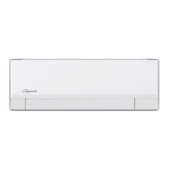
Installation Manual - VMHxxSV Unit Specifications and Features Indoor unit display Air Filter (pull up) Front Panel Power Cable (Some Units) Remote Control Louver Boost Humidity Remote Control ECO intelligent eye Holder (Some Units) (some units) Display window “ ” “ ”Displays temperature, operation feature and Error codes: “... -
Page 9: Operating Temperature
Installation Manual - VMHxxSV Operating temperature When your air conditioner is used outside of the following temperature ranges, certain safety protection features may activate and cause the unit to disable. Inverter Split Type FOR OUTDOOR UNITS COOL mode HEAT mode DRY mode WITH BASEPAN HEATER 17°C - 32°C... -
Page 10: Other Features
Installation Manual - VMHxxSV A guide on using the infrared remote is in a Refrigerant Leakage Detection • (some units) separate manual. Not all the functions are The indoor unit will automatically display “EL0C” when it detects refrigerant leakage. available for the air conditioner, please check the indoor display and remote control of the ECO Intelligent eye •... -
Page 11: Setting Angle Of Airflow
Installation Manual - VMHxxSV Setting Angle of Air Flow • Setting vertical angle of air flow While the unit is on, use the SWING button on remote control to set the direction (vertical angle) of airflow. Please refer to the Remote Control Manual for details. -
Page 12: Care And Maintenance
Installation Manual - VMHxxSV Care and Maintenance Rinse the filter with fresh water, then shake Cleaning Your Indoor Unit off excess water. Dry it in a cool, dry place, and refrain from BEFORE CLEANING OR exposing it to direct sunlight. MAINTENANCE When dry, re-clip the air freshening filter to ALWAYS TURN OFF YOUR AIR CONDITIONER... - Page 13 Installation Manual - VMHxxSV Maintenance – CAUTION Long Periods of Non-Use Before changing the filter or cleaning, • turn off the unit and disconnect its power If you plan not to use your air conditioner for an extended period of time, do the following: supply.
-
Page 14: Troubleshooting
Installation Manual - VMHxxSV Troubleshooting SAFETY PRECAUTIONS If ANY of the following conditions occurs, turn off your unit immediately! The power cord is damaged or abnormally warm • You smell a burning odor • The unit emits loud or abnormal sounds •... - Page 15 Installation Manual - VMHxxSV Issue Possible Causes The outdoor unit The unit will make different sounds based on its current operating mode. makes noises Dust is emitted from The unit may accumulate dust during extended periods of non-use, which will be either the indoor or emitted when the unit is turned on.
- Page 16 Installation Manual - VMHxxSV Problem Possible Causes Solution Wait for the power to be restored Power failure The power is turned off Turn on the power The unit is not The fuse is burned out Replace the fuse working Replace batteries Remote control batteries are dead The Unit’s 3-minute protection Wait three minutes after restarting...
-
Page 17: Accessories
Installation Manual - VMHxxSV Accessories The air conditioning system comes with the following accessories. Use all of the installation parts and accessories to install the air conditioner. Improper installation may result in water leakage, electrical shock and fire, or cause the equipment to fail. The items are not included with the air conditioner must be purchased separately. -
Page 18: Installation Summary - Indoor Unit
Installation Manual - VMHxxSV Installation Summary - Indoor Unit M M i i n n i i m m u u m m c c l l e e a a r r a a n n c c e e - - 3 3 " " 0"... -
Page 19: Unit Parts
Installation Manual - VMHxxSV Unit Parts NOTE: The installation must be performed in accordance with the requirement of local and national standards. The installation may be slightly different in different areas. Air-break switch Boost Humidity (1) (2) Remote Controller Air filter(pull it out) Wall Mounting Plate Remote Controller Holder Drainage Pipe... -
Page 20: Indoor Unit Installation
Installation Manual - VMHxxSV Indoor Unit Installation Refer to the following diagram to ensure Refer to the following diagram to ensure Installation Instructions – Indoor unit proper distance from walls and ceiling: proper distance from walls and ceiling: M M i i n n i i m m u u m m c c l l e e a a r r a a n n c c e e - - 3 3 " " PRIOR TO INSTALLATION R R e e c c o o m m e e n n d d e e d d c c l l e e a a r r a a n n c c e e - - 6 6 "... -
Page 21: Drill Wall Hole For Connective Piping
Installation Manual - VMHxxSV Step 3: Drill wall hole for connective piping Unit: mm(inch) 1. Determine the location of the wall hole based Horizontal direction ruler on the position of the mounting plate. Refer to Mounting Plate Dimensions. Vertical direction 2. -
Page 22: Prepare Refrigerant Piping
Installation Manual - VMHxxSV Step 4: Prepare refrigerant piping If refrigerant piping is already embedded in The refrigerant piping is inside an insulating the wall, do the following: sleeve attached to the back of the unit. You must Step 1:Hook the indoor unit on the mounting prepare the piping before passing it through the plate: hole in the wall. - Page 23 Installation Manual - VMHxxSV If there is no refrigerant piping embedded in the wall, do the following: Open the cover and unscrew the Based on the position of the wall hole relative screws to the mounting plate, choose the side from which the piping will exit the unit.
-
Page 24: Connect Drain Hose
Installation Manual - VMHxxSV Step 5: Connect drain hose BEFORE PERFORMING ANY By default, the drain hose is attached to the left- ELECTRICAL WORK, READ THESE hand side of unit (when you’re facing the back REGULATIONS of the unit). However, it can also be attached to the right-hand side. -
Page 25: Connect Signal And Power Cables
Installation Manual - VMHxxSV Step 6: Connect signal and power cables WARNING The signal cable enables communication between the indoor and outdoor units. You must first choose ALL WIRING MUST BE PERFORMED the right cable size before preparing it for connection. STRICTLY IN ACCORDANCE WITH THE Cable Types WIRING DIAGRAM LOCATED ON THE... -
Page 26: Wrap Piping And Cables
Installation Manual - VMHxxSV DO NOT INTERTWINE SIGNAL CABLE WITH OTHER WIRES While bundling these items together, do not intertwine or cross the signal cable with any other wiring. 2. Using adhesive vinyl tape, attach the drain hose to the underside of the refrigerant pipes. Using insulation tape, wrap the signal wire, refrigerant pipes, and drain hose tightly CAUTION... -
Page 27: Outdoor Unit Installation
Installation Manual - VMHxxSV Outdoor Unit Installation Install the unit by following local codes and install unit in the following locations: DO NOT regulations , there may be differ slightly between different regions. Near an obstacle that will block air inlets Outdoor Unit Installation and outlets Near a public street, crowded areas, or... -
Page 28: Install Drain Joint
Installation Manual - VMHxxSV Step 2: Install drain joint(Heat pump unit only) Step 3: Anchor outdoor unit Before bolting the outdoor unit in place, you must The outdoor unit can be anchored to the install the drain joint at the bottom of the unit. ground or to a wall-mounted bracket with Note that there are two different types of drain bolt(M10). - Page 29 Installation Manual - VMHxxSV Outdoor Unit Dimensions (mm) Mounting Dimensions W x H x D Distance A (mm) Distance B (mm) 681x434x285 (26.8”x 17.1”x 11.2”) 460 (18.1”) 292 (11.5”) 700x550x270 (27.5”x 21.6”x 10.6”) 450 (17.7”) 260 (10.2”) 450 (17.7”) 260 (10.2”) 700x550x275 (27.5”x 21.6”x 10.8”) 720x495x270 (28.3”x 19.5”x 10.6”) 255 (10.0”)
-
Page 30: Connect Signal And Power Cables
Installation Manual - VMHxxSV Step 4: Connect signal and power cables 7. Insulate unused wires with PVC electrical tape. Arrange them so that they do not touch any The outside unit’s terminal block is protected by electrical or metal parts. an electrical wiring cover on the side of the unit. -
Page 31: Refrigerant Piping Connection
Installation Manual - VMHxxSV Refrigerant Piping Connection When connecting refrigerant piping, do not let substances or gases other than the specified refrigerant enter the unit. The presence of other gases or substances will lower the unit’s capacity, and can cause abnormally high pressure in the refrigeration cycle. This can cause explosion and injury. -
Page 32: Remove Burrs
Installation Manual - VMHxxSV Step 2: Remove burrs PIPING EXTENSION BEYOND FLARE FORM Burrs can affect the air-tight seal of refrigerant Outer Diameter of A (mm) piping connection. They must be completely Max. Pipe (mm) Min. Max. removed. Ø 6.35 (Ø 0.25”) 0.7 (0.0275”) 1.3 (0.05”) Hold the pipe at a downward angle to prevent... - Page 33 Installation Manual - VMHxxSV Tighten the flare nut as tightly as possible by hand. Using a spanner, grip the nut on the unit tubing. While firmly gripping the nut on the unit tubing, use a torque wrench to tighten the flare nut according to the torque values in the Torque Requirements table below.
-
Page 34: Air Evacuation
Installation Manual - VMHxxSV Air Evacuation If there is a change in system pressure, refer Preparations and Precautions to Gas Leak Check section for information Air and foreign matter in the refrigerant circuit can on how to check for leaks. If there is no change in system pressure, cause abnormal rises in pressure, which can damage unscrew the cap from the packed... -
Page 35: Note On Adding Refrigerant
Installation Manual - VMHxxSV Note on Adding Refrigerant Some systems require additional charging depending on pipe lengths. The standard pipe length varies according to local regulations. For example, in North America, the standard pipe length is 7.5m (25’). In other areas, the standard pipe length is 5m (16‘). The refrigerant should be charged from the service port on the outdoor unit’s low pressure valve. -
Page 36: Electrical And Gas Leak Checks
Installation Manual - VMHxxSV Electrical and Gas Leak Checks Before Test Run WARNING – RISK OF ELECTRIC SHOCK Only perform test run after you have completed ALL WIRING MUST COMPLY WITH LOCAL the following steps: AND NATIONAL ELECTRICAL CODES, Electrical Safety Checks – Confirm that •... -
Page 37: Test Run
Installation Manual - VMHxxSV Test Run DOUBLE-CHECK PIPE CONNECTIONS Test Run Instructions During operation, the pressure of the You should perform the Test Run for at least 30 refrigerant circuit will increase. This may minutes. reveal leaks that were not present during your Connect power to the unit. - Page 38 Installation Manual - VMHxxSV NOTES __________________________________ __________________________________ __________________________________ __________________________________ __________________________________ __________________________________ __________________________________ __________________________________ __________________________________ __________________________________ __________________________________ __________________________________ __________________________________ __________________________________ __________________________________ __________________________________ __________________________________ __________________________________ __________________________________...
- Page 39 If for any reason the replacement part/product is no longer available during for normal use and maintenance for ten (10) years from the date of purchase the warranty period, MARS shall have the right to allow a credit in the by the original consumer for the original installation. This Express Limited...
- Page 40 Installation Manual - VMHxxSV 1/2023...
Need help?
Do you have a question about the Comfort-Aire Century VMH09 SV Series and is the answer not in the manual?
Questions and answers