Table of Contents
Advertisement
13-9-663
Version: 02
June 15, 2009
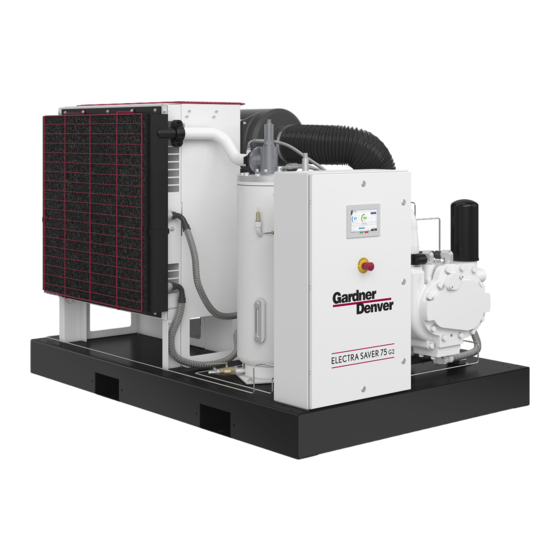
ELECTRA SCREW
ELECTRA-SAVER
ELECTRA-SAVER II
STATIONARY BASE-MOUNTED
COMPRESSOR
®
AUTO SENTRY
-- ES+ CONTROLS
EAH99C, EBH99G - 40, 50 HP
EAM99C, EBM99K - 60, 75 HP
ERH99E, EAP99J, EBP99J - 100 HP
INTERNATIONAL MODELS
EBM99L 60, 75, 100 HP (45, 56, 75 KW)
OPERATING AND
SERVICE MANUAL
Advertisement
Table of Contents


Need help?
Do you have a question about the EAH99C and is the answer not in the manual?
Questions and answers
I have an electra-saver II and the tag on the base says EBE99N11, I'm wondering what manual is the right one