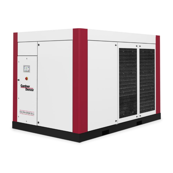
Gardner Denver ELECTRA SAVER Operating & Service Manual
Base mounted compressor
Hide thumbs
Also See for ELECTRA SAVER:
- Operating and service manual (105 pages) ,
- Operating and service manual (82 pages) ,
- Operating and service manual (20 pages)


Need help?
Do you have a question about the ELECTRA SAVER and is the answer not in the manual?
Questions and answers