Sign In
Upload
Manuals
Brands
Gardner Denver Manuals
Air Compressor
ERH99E
Gardner Denver ERH99E Rotary Compressor Manuals
Manuals and User Guides for Gardner Denver ERH99E Rotary Compressor. We have
1
Gardner Denver ERH99E Rotary Compressor manual available for free PDF download: Operating And Service Manual
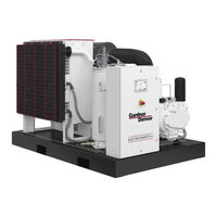
Gardner Denver ERH99E Operating And Service Manual (76 pages)
STATIONARY BASE-MOUNTED COMPRESSOR
Brand:
Gardner Denver
| Category:
Air Compressor
| Size: 1.14 MB
Table of Contents
Maintain Compressor Reliability and Performance with Genuine Gardner Denver Compressor Parts and Support Services
2
Instructions for Ordering Repair Parts/Remanufactured Airends
2
Warning - Prohibition - Mandatory Label Information
3
Safety Precautions
5
Table of Contents
6
Index
7
List of Illustrations
9
Section 1, General Information
10
Figure 1-1 - Compression Cycle
10
Figure 1-2 - Starter Box
11
Figure 1-3 - Control Box
11
Figure 1-4 - Compressor / Motor Side
12
Figure 1-5 - Cooler / Reservoir Side
12
Figure 1-6 - Air/Oil Flow Diagram
13
Section 2, Installation
14
Figure 2-1 - Typical Compressor Room
15
Figure 2-2 - Air Flow Chart
15
Figure 2-3 - Cold Weather Installation
17
Figure 2-4 - Inlet Line Lengths
18
Figure 2-5 - Heat Exchanger (Oil Cooler) Approximate Water Flow
19
Figure 2-6 - Aftercooler Approximate Water Flow
20
Figure 2-7 - Series Piping
21
Figure 2-8 - Parallel Piping
21
Section 3, Starting & Operating Procedures
24
Section 4, Controls & Instrumentation
27
Figure 4-1 - Schematic Tubing Diagram
28
Figure 4-2 - Blowdown Valve
29
Figure 4-3 - Minimum Discharge Pressure/Check Valve
29
Figure 4-4 - Inlet Valve
30
Figure 4-5 - Shuttle Valve
31
Figure 4-6 - Turn Valve - Electra-Saver Only
32
Figure 4-7 - Control Schematic - Compressor Unloaded - Constant Speed Mode
35
Figure 4-8 - Control Schematic - Compressor at Full Load - Constant Speed Mode
36
Figure 4-9 - Control Schematic - Compressor Unloaded - Low Demand Mode or Auto Mode
37
Figure 4-10 - Control Schematic - Compressor at Full Load
38
Figure 4-11 - Control Schematic - Compressor Fully Unloaded - Low Demand Mode Switch off
39
Figure 4-12 - Control Schematic - Compressor Fully Loaded - Low Demand Mode Switch on
40
Figure 4-13 - Wiring Diagram - Wye Delta
41
Figure 4-14 - Wiring Diagram - Full Voltage
42
Figure 4-15 - Wiring Diagram - Wye Delta
43
Figure 4-16 - Wiring Diagram - Full Voltage
44
Section 5, Lubrication, Oil Cooler, Oil Filter & Separator
45
Figure 5-1 - Dew Point Chart °F
47
Figure 5-2 - Dew Point Chart °C
47
Figure 5-3 - Flow Diagram - Air/Oil System
48
Figure 5-4 - Oil Flow Diagram - Remote Overhead Mounted Cooler
49
Figure 5-5 - Cooler Drain Detail
50
Figure 5-6 - Oil Level Gauge
53
Figure 5-7 - Oil Change Interval
54
Figure 5-8 - Approximate Oil System Capacities
55
Figure 5-9 - Thermostatic Mixing Valve Element
57
Figure 5-10 - Water Control Valve
58
Figure 5-11 - Dew Point Temperature Vs. Ambient Temperature
59
Figure 5-12 - Oil Separator
60
Section 6, Air Filter
64
Figure 6-1 - Heavy Duty Air Filter
64
Section 7, Coupling
66
Figure 7-1 - Installation of Coupling Cushions
66
Section 8, Maintenance Schedule
69
Section 9, Troubleshooting
71
Advertisement
Advertisement
Related Products
Gardner Denver ELECTRA-SCREW EDEQHJ
Gardner Denver ELECTRA-SAVER EBQ99M
Gardner Denver EDF-LB
Gardner Denver EBU99D
Gardner Denver EBM99M 60
Gardner Denver AUTO SENTRY EAU99R
Gardner Denver EBHQHC
Gardner Denver EBMSKE
Gardner Denver EBMSME
Gardner Denver ELECTRA-SAVER EAQQM
Gardner Denver Categories
Air Compressor
Water Pump
Dehumidifier
Controller
Blower
More Gardner Denver Manuals
Login
Sign In
OR
Sign in with Facebook
Sign in with Google
Upload manual
Upload from disk
Upload from URL