Baumer VCXG.2 Series Operating Manual
Hide thumbs
Also See for VCXG.2 Series:
- Operating manual (220 pages) ,
- Operating instructions manual (240 pages)

Related Manuals for Baumer VCXG.2 Series


Summary of Contents for Baumer VCXG.2 Series
- Page 1 Operating Manual VCXG.2 / VCXG.2.XC / VCXG.2.I / VCXU.2 EN-US (Gigabit Ethernet / USB3.0)
-
Page 2: Table Of Contents
List of contents Baumer List of contents 1 About this document ..........................11 Purpose............................... 11 Warnings in this manual........................11 Labels in this manual .......................... 12 Liability limitation ..........................12 Copyright............................. 12 2 General information ............................ 13 3 Description..............................14 VCXG.2 ............................... - Page 3 9 Troubleshooting ............................75 Support..............................75 Accessories............................75 10 Software ............................... 76 10.1 Baumer GAPI ............................76 10.2 Baumer neoAPI........................... 76 10.3 Baumer Camera Explorer ........................76 10.4 3 Party Software..........................76 V1.2 | VCXG.2 / VCXG.2.XC / VCXG.2.I / VCXU.2 Operating Manual...
- Page 4 List of contents Baumer 11 GenICam Camera Features ........................77 11.1 Category: AcquisitionControl....................... 77 11.1.1 AcquisitionAbort ........................77 11.1.2 AcquisitionFrameCount......................78 11.1.3 AcquisitionFrameRate......................78 11.1.4 AcquisitionFrameRateEnable ....................78 11.1.5 AcquisitionMode........................79 11.1.6 AcquisitionStart ........................79 11.1.7 AcquisitionStatus ........................79 11.1.8 AcquisitionStatusSelector .....................
- Page 5 Baumer List of contents 11.4.12 ExposureAutoMinValue ......................106 11.4.13 GainAutoMaxValue ....................... 106 11.4.14 GainAutoMinValue ........................ 106 11.5 Category: ChunkDataControl ......................107 11.5.1 ChunkEnable ........................108 11.5.2 ChunkModeActive......................... 108 11.5.3 ChunkSelector ........................108 11.6 Category: ColorTransformationControl (color cameras only).............. 110 11.6.1 ColorTransformationAuto......................
- Page 6 List of contents Baumer 11.9.15 DeviceSFNCVersionMajor ....................125 11.9.16 DeviceSFNCVersionMinor ....................126 11.9.17 DeviceSFNCVersionSubMinor....................126 11.9.18 DeviceScanType........................126 11.9.19 DeviceSensorType........................ 126 11.9.20 DeviceSerialNumber ......................127 11.9.21 DeviceStreamChannelCount ....................127 11.9.22 DeviceStreamChannelEndianness ..................127 11.9.23 DeviceStreamChannelSelector..................... 127 11.9.24 DeviceStreamChannelType ....................128 11.9.25 DeviceTLType........................
- Page 7 Baumer List of contents 11.11.1 EventNotification ........................150 11.11.2 EventSelector........................150 11.11.3 LostEventCounter ......................... 151 11.12 Category: ImageFormatControl......................151 11.12.1 BinningHorizontal........................155 11.12.2 BinningHorizontalMode......................158 11.12.3 BinningSelector........................158 11.12.4 BinningVertical ........................158 11.12.5 BinningVerticalMode ......................161 11.12.6 Category: ImageFormatControl → CalibrationControl (MP cameras only)......161 11.12.6.1...
- Page 8 List of contents Baumer 11.15.3 SequencerFeatureSelector ....................190 11.15.4 SequencerMode ........................191 11.15.5 SequencerPathSelector ......................191 11.15.6 SequencerSetActive ......................192 11.15.7 SequencerSetLoad ....................... 192 11.15.8 SequencerSetNext........................ 192 11.15.9 SequencerSetSave ....................... 192 11.15.10SequencerSetSelector ......................193 11.15.11SequencerSetStart ....................... 193 11.15.12SequencerTriggerActivation ....................193 11.15.13SequencerTriggerSource......................
- Page 9 Baumer List of contents 11.17.2.35 GevSCPSFireTestPacket ................. 205 11.17.2.36 GevSCPSPacketSize ..................205 11.17.2.37 GevSCSP ......................206 11.17.2.38 GevSecondURL ....................206 11.17.2.39 GevStreamChannelSelector................206 11.17.2.40 GevSupportedOption..................206 11.17.2.41 GevSupportedOptionSelector ................207 11.17.2.42 InterfaceSpeedMode ..................207 11.17.3 PayloadSize .......................... 207 11.17.4 Category: PtpControl ......................208 11.17.4.1...
- Page 10 List of contents Baumer 13 GigE interface functionality........................225 13.1 packet size and Maximum Transmission Unit (MTU)................225 13.2 Inter Packet Gap (IPG)........................225 13.3 Frame Transmission Delay ......................... 227 13.4 Multicast .............................. 230 13.5 IP-Konfiguration ..........................231 13.5.1 Persistent IP.......................... 231 13.5.2...
-
Page 11: About This Document
In addition, the local occupational health and safety regulations and general safety regulations apply. The illustrations in this manual are examples only. Deviations are at the discretion of Baumer at all times. Warnings in this manual Warnings draw attention to potential personal injury or material damage. -
Page 12: Labels In This Manual
Any duplication or reprinting of this documentation, in whole or in part, and the reproduction of the illustrations even in modified form is permitted only with the written approval of Baumer. The information in this document is subject to change without notice. -
Page 13: General Information
Used electrical and electronic devices may not be disposed of in household waste. The product contains valuable raw materials that can be recycled. There- fore dispose of this product at the appropriate collection point. For additional in- formation visit www.baumer.com. V1.2 | VCXG.2 / VCXG.2.XC / VCXG.2.I / VCXU.2 Operating Manual... -
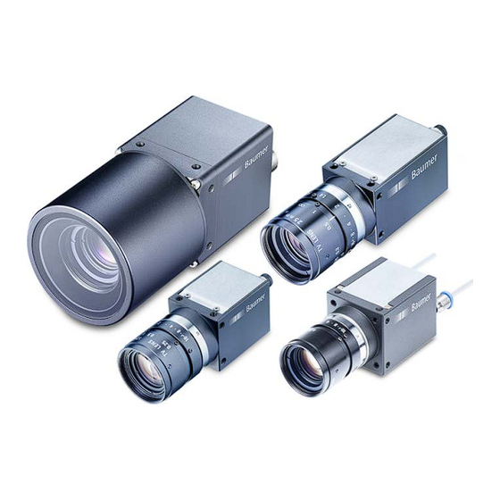
Page 14: Description
Description Baumer Description VCXG.2 3.1.1 Conception Lens mount (C-mount) Power supply / Digital IO Network connection with LEDs 3.1.2 LED status indicator Signal Meaning green Connection active green flashing receiving data yellow Error yellow flashing Transmitting data Operating Manual VCXG.2 / VCXG.2.XC / VCXG.2.I / VCXU.2 | V1.2... -
Page 15: Camera Models
Baumer Description 3.1.3 Camera models Camera type Sensor size Resolution Max. FPS (Width × Height) Monochrom VCXG.2-13M 1/2" 1280 × 1024 145 | 94 VCXG.2-15M 1/1.8" 1440 × 1080 120 | 79 VCXG.2-25M 2/3" 1920 × 1200 59 | 53 VCXG.2-32M... -
Page 16: Dimensional Drawing
Description Baumer 3.1.4 Dimensional drawing 2 x M3 x 4 8 x M3 x 4 C-mount 48,9 6,6 ±0,35 4,45 Ill. 1: Dimensional drawing - VCXG Operating Manual VCXG.2 / VCXG.2.XC / VCXG.2.I / VCXU.2 | V1.2... -
Page 17: Vcxg.2.Xc
Baumer Description VCXG.2.XC 3.2.1 Conception Lens mount (C-mount) Cooling channel (inlet) Cooling channel (outlet) Network connection Power supply / Digital IO 3.2.2 LED status indicator Signal Meaning green Connection active green flashing receiving data yellow Error yellow flashing Transmitting data V1.2 | VCXG.2 / VCXG.2.XC / VCXG.2.I / VCXU.2... -
Page 18: Camera Models
Description Baumer 3.2.3 Camera models Camera type Sensor size Resolution Max. FPS (Width × Height) Monochrom VCXG.2-51M.XC 2/3" 2448 × 2048 35.5 | 23.5 VCXG.2-241M.XC 1.2" 5312 × 4592 5 | 5 Image is acquired to the camera's internal memory | Interface 3.2.4... -
Page 19: Vcxg.2.I
Baumer Description VCXG.2.I 3.3.1 Conception Lens mount (C-mount) 4 x tube adapter with front mounting threads Power supply / Digital IO Network connection GigE status indicator 3.3.2 LED status indicator Signal Meaning yellow Error yellow flashing Transmitting data green Connection active... -
Page 20: Camera Models
Description Baumer 3.3.3 Camera models Camera type Sensor size Resolution Max. FPS (Width × Height) Monochrom VCXG.2-15M.I 1/1.8" 1440 × 1080 120 | 79 VCXG.2-32M.I 1/1.8" 2048 × 1536 55.5 | 39.5 VCXG.2-51M.I 2/3" 2448 × 2048 35.5 | 23.5 VCXG.2-57M.I... -
Page 21: Dimensional Drawing
Baumer Description 3.3.4 Dimensional drawing 38,4 8,33 2 x M3 x 5 8 x M3 x5 temperature measurement point Ø 28,7 18,6 10,7 12,9 10,2 50,8 6,95 Ill. 3: Dimensional drawing - VCXG.I V1.2 | VCXG.2 / VCXG.2.XC / VCXG.2.I / VCXU.2... -
Page 22: Vcxu.2
Description Baumer VCXU.2 3.4.1 Conception Lens connection (C-mount) Digital-IO USB3.0 3.4.2 LED status indicator Signal Meaning green flashing Power on green continuous Connection via USB 3.0 Connection via USB 2.0 yellow Data traffic red flashing Update Operating Manual VCXG.2 / VCXG.2.XC / VCXG.2.I / VCXU.2 | V1.2... -
Page 23: Camera Models
Baumer Description 3.4.3 Camera models Camera type Sensor size Resolution Max. FPS (Width × Height) Monochrom VCXU.2-13.M 1/2" 1280 × 1024 VCXU.2-15.M 1/2.9" 1440 × 1080 VCXU.2-31.M 1/1.8" 2048 × 1536 VCXU.2-32.M 1/1.8" 2048 × 1536 55.5 VCXU.2-50.M 2/3" 2448 × 2048 VCXU.2-50.MP... -
Page 24: Dimensional Drawing
Description Baumer 3.4.4 Dimensional drawing 2 x M3 x 4 8 x M3 x 4 C-mount 37,8 6,6 ±0,35 6,15 Ill. 4: Dimensional drawing - VCXU Operating Manual VCXG.2 / VCXG.2.XC / VCXG.2.I / VCXU.2 | V1.2... -
Page 25: Transport And Storage
Baumer Transport and storage Transport and storage Transport NOTICE Material damage due to improper transport. a) Ensure maximum diligence when unloading the delivered packages as well as when trans- porting them inside the company. b) Note the information and symbols on the packaging. -
Page 26: Installation
Installation Baumer Installation Environmental requirements Storage temperature VCXG.2 -10 °C (+14 °F) ... +70 °C (+158 °F) VCXG.2.XC -10 °C (+14 °F) ... +70 °C (+158 °F) VCXG.2.I -10 °C (+14 °F) ... +70 °C (+158 °F) VCXU.2 -10 °C (+14 °F) ... +70 °C (+158 °F) Operating tempera- VCXG.2... -
Page 27: Mechanical Tests
Baumer Installation Mechanical Tests Baumer cameras are tested towards the following standards to ensure industrial suitability. Test environment Standard Parameter Vibration, sinusoidal IEC 60068-2-6 Continuous oscillation 10-2000 Hz Amplitude underneath 1.5 mm crossover frequencies Acceleration 10 g Test duration 150 min (axis) -
Page 28: Emergency Shutdown At Overtemperature
Installation Baumer Emergency shutdown at Overtemperature To prevent damage on the hardware due to high temperatures, the camera features emergency shutdown. Function DeviceTemperatureStatusTransitionSelector (Category: DeviceControl) is to select temperature thresholds: NormalToHigh: freely programmable value HighToExeeded: fixed value (camera shutdown if exceeded) - Page 29 Baumer Installation Temperatures for emergency-off As soon as the temperature measured at the internal temperature sensor is exceeding the val- ues specified in the table below, function DeviceTemperatureExceeded is set to True and image acquisition stops. VCXG.2 Camera type max. temperature (internal sensor) Monochrom / Color VCXG.2-13M / VCXG.2-13C...
- Page 30 Installation Baumer VCXU.2 Camera type Max. temperature (internal sensor) Monochrom / Color VCXU.2-13M / VCXU.2-13C 75 °C (167 °F) VCXU.2-15M / VCXU.2-15C 72 °C (161.6 °F) VCXU.2-31M / VCXU.2-31C 72 °C (161.6 °F) VCXU.2-32M / VCXU.2-32C 72 °C (161.6 °F) VCXU.2-50M / VCXU.2-50C...
-
Page 31: Heat Dissipation
Heat accumulation in the device Heat can damage the device. Provide adequate dissipation of heat. As there are numerous pos- sibilities for installation, Baumer recommends no specific method for proper heat dissipation, but suggest the following principle: a) Every form of convection around the device and mounting helps reduce temperature. Pre- vent heat from becoming trapped! b) Mounting in combination with forced convection may provide proper heat dissipation. -
Page 32: Cooling Channel (Vcxg.2.Xc Only)
Installation Baumer 5.4.1 Cooling channel (VCXG.2.XC only) The camera features a housing-integrated cooling channel. This is to feed compressed air or tempering fluid for camera temperature control. For compressed air / tempering fluid connection (inlet (1) / outlet (2)) use male threaded M3 push-in fittings and plastic hoses, e.g. - Page 33 Baumer Installation Class Particle Water ≤ 5 ≤ 10 > 10 > 10 > 5 Cooling with tempering fluid The tempering fluid efficiently takes the heat away from the camera. cold air Heat exchanger Tank Pump Cooling channel (inlet) Cooling channel (outlet)
-
Page 34: Lens Mount
Installation Baumer Lens mount Avoid contamination of the sensor and the lens by dust and airborne particles when mounting the lens to the device! Therefore the following points are very important: Install the camera in an environment that is as dust free as possible! Keep the lens mount covered if no lens is attached Hold the camera downwards with unprotected sensor. -
Page 35: Modular Tube System (Please Order Separately)
Instruction: a) Mount the Modular Tube System as shown in the illustration below. b) Baumer recommends ELKALUB GLS 867 grease for easier installation of the sealing rings (5). c) Tighten the screws (3) with a torque wrench to 0.9 Nm. - Page 36 Installation Baumer Tube adapter M 47 M 62 3,25 3,25 2,75 2,75 5,25 5,25 Art. No.: 11185373 Art. No.: 11185377 M 92 3,25 2,75 5,25 11704311 Art. No.: Operating Manual VCXG.2 / VCXG.2.XC / VCXG.2.I / VCXU.2 | V1.2...
- Page 37 Baumer Installation Spacer M 47 M 62 O-Ring O-Ring Art. No.: 11185376 Art. No.: 11185372 O-Ring O-Ring Art. No.: 11185375 Art. No.: 11185371 O-Ring O-Ring Art. No.: 11198906 Art. No.: 11211571 V1.2 | VCXG.2 / VCXG.2.XC / VCXG.2.I / VCXU.2...
- Page 38 Installation Baumer M 92 O-Ring Art. No.: 11704395 7.25 O-Ring Art. No.: 11704397 7.25 O-Ring Art. No.: 11704394 Operating Manual VCXG.2 / VCXG.2.XC / VCXG.2.I / VCXU.2 | V1.2...
- Page 39 Baumer Installation Tube M 47 M 62 54,5 40,5 Art. No.: 11185374 (Cover Glass: Acryl) Art. No.: 11185370 (Cover Glass: Acryl) Art. No.: 11195426 (Cover Glass: restistant laminated safety cover glass) Art. No.: 11195425 (Cover Glass: restistant laminated safety cover glass) M 92 66.5...
- Page 40 Installation Baumer M 92 Operating Manual VCXG.2 / VCXG.2.XC / VCXG.2.I / VCXU.2 | V1.2...
-
Page 41: Optical Specification
Baumer Optical specification Optical specification VCXG.2 6.1.1 Sensor position accuracy Typical precision under assumption of the average square root value is shown in the figure and table(s) below. ± XM ± XR photosensitive surface of the sensor front filter glass... -
Page 42: Filter Glass Color Cameras
Optical specification Baumer 6.1.2 Filter glass color cameras 100% 1000 1100 1200 Wavelength in nm Filter glass of color cameras Filter glass color cameras 6.1.3 Spectral sensitivity The following diagrams show the spectral sensitivity characteristics for this camera series. The characteristic curves for the sensors do not take the characteristics of lenses and light sources without filters into consideration. - Page 43 Baumer Optical specification 6000 6000 5000 5000 4000 4000 3000 3000 2000 2000 1000 1000 1000 1100 1000 1100 ® ® ON Semiconductor PYTHON 2000 mono ON Semiconductor PYTHON 2000 color Wave Length [nm] Wave Length [nm] Spectral sensitivity VCXG.2-25M Spectral sensitivity VCXG.2-25C...
- Page 44 Optical specification Baumer 1000 1000 ® ® Sony IMX 548 mono Sony IMX 548 color Wave Length [nm] Wave Length [nm] Spectral sensitivity VCXG.2-57M Spectral sensitivity VCXG.2-57C ® ® (Sony IMX548) (Sony IMX548) 1000 ® Sony IMX 178 mono Wave Length [nm] Sony ®...
- Page 45 Baumer Optical specification 1000 1000 ® ® Sony 304 mono Sony 304 color Wave Length [nm] Wave Length [nm] Spectral sensitivity VCXG.2-124M Spectral sensitivity VCXG.2-124C ® ® (Sony IMX304) (Sony IMX304) 1000 1000 ® ® Sony IMX 545 mono Sony...
- Page 46 Optical specification Baumer 1000 1000 ® ® Sony IMX 541 mono Sony IMX 541 color Wave Length [nm] Wave Length [nm] Spectral sensitivity VCXG.2-204M Spectral sensitivity VCXG.2-204C ® ® (Sony IMX541) (Sony IMX541) 1000 1000 ® ® Sony IMX 540 mono...
-
Page 47: Vcxg.2.Xc
Baumer Optical specification VCXG.2.XC 6.2.1 Sensor position accuracy Typical precision under assumption of the average square root value is shown in the figure and table(s) below. ± XM ± XR photosensitive surface of the sensor front filter glass for color cameras thickness: 1 ±... -
Page 48: Spectral Sensitivity
Optical specification Baumer 6.2.2 Spectral sensitivity The following diagrams show the spectral sensitivity characteristics for this camera series. The characteristic curves for the sensors do not take the characteristics of lenses and light sources without filters into consideration. The values refer to the related data sheets. -
Page 49: Vcxg.2.I
Baumer Optical specification VCXG.2.I 6.3.1 Sensor position accuracy Typical precision under assumption of the average square root value is shown in the figure and table(s) below. ± XM ± XR photosensitive surface of the sensor front filter glass for color cameras thickness: 1 ±... -
Page 50: Filter Glass Color Cameras
Optical specification Baumer 6.3.2 Filter glass color cameras 100% 1000 1100 1200 Wavelength in nm Filter glass of color cameras Filter glass color cameras 6.3.3 Cover glasses Tubes 100% 100% 1000 1100 1200 1000 1100 1200 Wavelength in nm Wavelength in nm... - Page 51 Baumer Optical specification 1000 1000 ® Sony IMX 265 color Wave Length [nm] Sony ® IMX 250 mono Wave Length [nm] Spectral sensitivity VCXG.2-32M.I Spectral sensitivity VCXG.2-32C.I ® ® (Sony IMX265) (Sony IMX265) 1000 1000 Sony ® IMX 264 mono ®...
- Page 52 Optical specification Baumer 1000 1000 ® ® Sony IMX 546 mono Sony IMX 546 color Wave Length [nm] Wave Length [nm] Spectral sensitivity VCXG.2-82M.I Spectral sensitivity VCXG.2-82C.I ® ® (Sony IMX546) (Sony IMX546) 1000 1000 ® ® Sony IMX 545 mono...
- Page 53 Baumer Optical specification 1000 1000 ® ® Sony IMX 540 mono Sony IMX 540 color Wave Length [nm] Wave Length [nm] Spectral sensitivity VCXG.2-241M.I Spectral sensitivity VCXG.2-241C.I ® ® (Sony IMX540) (Sony IMX540) V1.2 | VCXG.2 / VCXG.2.XC / VCXG.2.I / VCXU.2...
-
Page 54: Vcxu.2
Optical specification Baumer VCXU.2 6.4.1 Sensor position accuracy Typical precision under assumption of the average square root value is shown in the figure and table(s) below. ± XM ± XR photosensitive surface of the sensor front filter glass for color cameras thickness: 1 ±... -
Page 55: Filter Glass Color Cameras
Baumer Optical specification 6.4.2 Filter glass color cameras 100% 1000 1100 1200 Wavelength in nm Filter glass of color cameras Filter glass color cameras 6.4.3 Spectral sensitivity The following diagrams show the spectral sensitivity characteristics for this camera series. The characteristic curves for the sensors do not take the characteristics of lenses and light sources without filters into consideration. - Page 56 Optical specification Baumer 1000 1000 Sony ® IMX 252 mono Sony ® IMX 252 color Wave Length [nm] Wave Length [nm] Spectral sensitivity VCXU.2-31M Spectral sensitivity VCXU.2-31C ® ® (Sony IMX252) (Sony IMX252) 1000 1000 Sony ® IMX 265 color...
- Page 57 Baumer Optical specification 1000 ® Sony IMX 250MZR-C Wave Length [nm] Spectral sensitivity VCXU.2-50MP ® (Sony IMX250MZR-C) 1000 1000 ® Sony IMX 264 mono Wave Length [nm] Sony ® IMX 264 color Wave Length [nm] Spectral sensitivity VCXU.2-51M Spectral sensitivity VCXU.2-51C ®...
- Page 58 Optical specification Baumer 1000 ® Sony IMX 178 mono Wave Length [nm] Sony ® IMX 178 color Wave Length [nm] Spectral sensitivity VCXU.2-65M.R Spectral sensitivity VCXU.2-65C.R ® ® (Sony IMX178) (Sony IMX178) 1000 1000 ® ® Sony IMX 253 mono...
- Page 59 Baumer Optical specification 1000 ® Sony IMX 183 mono Wave Length [nm] Sony ® IMX 183 color Wave Length [nm] Spectral sensitivity VCXU.2-201M.R Spectral sensitivity VCXU.2-201C.R ® ® (Sony IMX183) (Sony IMX183) 1000 1000 Sony ® IMX 540 mono Sony ®...
-
Page 60: Electrical Installation
Electrical installation Baumer Electrical installation General instructions for electric installation NOTICE Device damage due to faulty power supply. The device can be damaged due to faulty power supply. a) Operate the device only with protected low voltage and safe electrical isolation of protection class III. - Page 61 Baumer Electrical installation NOTICE Ethernet interface damage by inappropriate connectors The camera features TYPE090 Ethernet interface. Using any other connector than TYPE090 could damage the connection. a) Only use cables with TYPE090 connector. Ground connection (1) TYPE090 TYPE110 (Do not use!) 9.0 mm (-0.50 + 0.00)
-
Page 62: Digital Io
Electrical installation Baumer 7.2.2 Digital IO Camera Customer Device Camera Customer Device IO Power V CC IO Power V CC I OUT Out (n) I OUT IO GND IO GND Digital Output: Low Active Digital Output: High Active Customer Device... -
Page 63: Gpio (General Purpose Input / Output)
Baumer Electrical installation 7.2.3 GPIO (General Purpose Input / Output) Line1 and Line2 are GPIOs and can be both Input and Output. Input: (0 ..0.8 V low, 2.0 ... 30 V high). Output:(0 ..0.4 V low, 2.4 ... 3.3 V high), @ 1 mA load (high) / 50 mA sink (low) -
Page 64: Vcxg.2.Xc
Electrical installation Baumer VCXG.2.XC 7.3.1 Pin assignment Power supply / Digital IO GPIO (Line2) Power V (12 … 24 VDC ± 20%) IN1 (Line0) GND IN1 Power V (OUT1) OUT1 (Line3) GND (Power, GPIO) GPIO (Line1) Cable core colors (cable not included in delivery) WH –... - Page 65 Baumer Electrical installation Ground connection (1) TYPE090 TYPE110 (Do not use!) 9.0 mm (-0.50 + 0.00) 11.0 mm (-0.47 + 0.00) 4.25 mm (-1.00 + 0.25) 4.25 mm (-1.00 + 0.25) Ground female connector (2) TYPE090 9.0 mm (-0.00 + 1.00) 4.5 mm (-0.00 + 1)
-
Page 66: Digital Io
Electrical installation Baumer 7.3.2 Digital IO Camera Customer Device Camera Customer Device IO Power V CC IO Power V CC I OUT Out (n) I OUT IO GND IO GND Digital Output: Low Active Digital Output: High Active Customer Device... -
Page 67: Gpio (General Purpose Input / Output)
Baumer Electrical installation 7.3.3 GPIO (General Purpose Input / Output) Line1 and Line2 are GPIOs and can be both Input and Output. Input: (0 ..0.8 V low, 2.0 ... 30 V high). Output:(0 ..0.4 V low, 2.4 ... 3.3 V high), @ 1 mA load (high) / 50 mA sink (low) -
Page 68: Vcxg.2.I
Electrical installation Baumer VCXG.2.I 7.4.1 Pin assignment Stromversorgung / Digital-IO Power V (12 … 24 VDC ± 20%) GND (Power) IN1 (Line0) OUT1 (Line4) IN2 (Line1) OUT2 (Line5) OUT3 (Line6) IN3 (Line2) OUT4 (Line7) IN4 (Line3) GND (IO) Power (IO) Cable core colors (cable not included in delivery) BN –... -
Page 69: Digital-Io
Baumer Electrical installation 7.4.2 Digital-IO Camera Pin 1 Power Vcc 12 – 24 V Pin 2 GND (Power) Line0 IN 1 Pin 3 current limiter cable termination IN 2 Line1 Pin 5 current limiter cable termination Pin 8 IN 3... -
Page 70: Vcxu.2
Electrical installation Baumer VCXU.2 7.5.1 Pin assignment Digital IO GPIO (Line2) not connected IN1 (Line0) GND IN1 Power V (OUT1) OUT1 (Line3) GND (Power, GPIO) GPIO (Line1) Cable core colors (cable not included in delivery) WH – White BN – Brown GN –... -
Page 71: Digital Io
Baumer Electrical installation 7.5.2 Digital IO Camera Customer Device Camera Customer Device IO Power V CC IO Power V CC I OUT Out (n) I OUT IO GND IO GND Digital Output: Low Active Digital Output: High Active Customer Device... -
Page 72: Gpio (General Purpose Input / Output)
Electrical installation Baumer 7.5.3 GPIO (General Purpose Input / Output) Line1 and Line2 are GPIOs and can be both Input and Output. Input: (0 ..0.8 V low, 2.0 ... 30 V high). Output:(0 ..0.4 V low, 2.4 ... 3.3 V high), @ 1 mA load (high) / 50 mA sink (low) -
Page 73: Preventive Maintenance
Baumer Preventive maintenance Preventive maintenance The sensor is maintenance-free. No special preventive maintenance is required. Regular clean- ing and regular checking of the plug connections are recommended. Cleaning Due to its compact design, the device is characterized by almost maintenance-free operation. - Page 74 Preventive maintenance Baumer Tube cover glass For cleaning, use a soft, lint-free cloth to clean the surface of the tube cover glass with a gentle pressure, without scratching. To clean stubborn dirt, commonly available window cleaning agent is recommended. Ensure that no residues of the cleaning agent or scratches remain on the glass. These can permanently damage the reproducibility of the results from the device.
-
Page 75: Troubleshooting
Baumer Troubleshooting Troubleshooting Support In case of any questions please contact our Technical & Application Support Center. Worldwide Baumer Optronic GmbH Badstrasse 30 DE - 01454 Radeberg www.baumer.com Tel.: +49 (0)3528 4386 845 support.cameras@baumer.com Accessories You can find accessories at the website at: https://www.baumer.com... -
Page 76: Software
Baumer Camera Explorer Easy-to-use Baumer Camera Explorer allows for camera evaluation and configuration within the least amount of time. It helps get to know and try the diversified functions of the Baumer cam- eras for configuration to the application. ®... -
Page 77: Genicam Camera Features
Baumer GenICam Camera Features GenICam Camera Features A GenICam™-compliant XML-description file presents the camera's Features. The following chapter describes all included and accessible functions. Most of the camera's functions are standardized in GenICam™ SFNC and must use the name defined in there. Particular Fea- tures, which cannot be assigned to an existing GenICam™... -
Page 78: Acquisitionframecount
GenICam Camera Features Baumer 11.1.2 AcquisitionFrameCount Number of frames to acquire in MultiFrame Acquisition mode. Name AcquisitionFrameCount Category AcquisitionControl Interface IInteger Access Read / Write Unit Values 1 - 65535 (Increment: 1) 11.1.3 AcquisitionFrameRate Controls the acquisition rate (in Hertz) at which the frames are captured. -
Page 79: Acquisitionmode
Baumer GenICam Camera Features 11.1.5 AcquisitionMode Sets the acquisition mode of the device. It defines mainly the number of frames to capture dur- ing an acquisition and the way the acquisition stops. INFO The camera must be stopped before this feature can be edited. -
Page 80: Acquisitionstatusselector
GenICam Camera Features Baumer 11.1.8 AcquisitionStatusSelector Selects the internal acquisition signal to be read by AcquisitionStatus. Name AcquisitionStatusSelector Category AcquisitionControl Interface IEnumeration Access Read / Write Unit Values Acquisition Ac- Device is currently doing an acquisition of one or many frames. -
Page 81: Exposuremode
Baumer GenICam Camera Features 11.1.11 ExposureMode Sets the operation mode of the Exposure. Name ExposureMode Category AcquisitionControl Interface IEnumeration Access Read / Write Unit Values Timed Time-controlled exposure. The exposure duration time is set using the ExposureTime or ExposureAuto features and the ex- posure starts with the FrameStart or LineStart. - Page 82 GenICam Camera Features Baumer INFO Sequencer will not be accessible if function ShortExposureTimeEnable is enabled. VCXG.2 Texposure Tnon- Texposure Texposure selectable [μsec] range [μsec] [sec] [μsec] (Default) Monochrom VCXG.2-13M VCXG.2-15M VCXG.2-25M VCXG.2-32M VCXG.2-51M VCXG.2-51MP VCXG.2-57M 4-19 VCXG.2-65M.R 16* / 34** 16.3* / 60**...
- Page 83 Baumer GenICam Camera Features VCXG.2.XC Texposure Tnon- Texposure Texposure selectable [μsec] range [μsec] [sec] [μsec] (Default) Monochrom VCXG.2-51M.XC VCXG.2-241M.XC 4 - 38 only if ShortExposureTimeEnable is enabled Range (ExposureTimeGapMin – ExposureTimeGapMax) only relevant if ShortExposure- TimeEnable is enabled VCXG.2.I Texposure...
- Page 84 GenICam Camera Features Baumer VCXU.2 Texposure Tnon- Texposure Texposure selectable [μsec] range [μsec] [sec] [μsec] (Default) Monochrom VCXU.2-13.M VCXU.2-15.M VCXU.2-31.M VCXU.2-32.M VCXU.2-50.M VCXU.2-50.MP VCXU.2-51.M VCXU.2-57.M 4 - 9 VCXU.2-65.M.R 10* / 22** 10.16* / 60** VCXU.2-123.M VCXU.2-127.M 4 – 14 VCXU.2-201.M.R...
-
Page 85: Exposuretimegapmax
Baumer GenICam Camera Features 11.1.13 ExposureTimeGapMax Returns the maximum value of the exposure time gap. Name ExposureTimeGapMax Category AcquisitionControl Interface IFloat Access Read only Unit µs Values 0 - 2,000,000.000000 (Increment: 1.00) 11.1.14 ExposureTimeGapMin Returns the minimum value of the exposure time gap. -
Page 86: Readoutmode
GenICam Camera Features Baumer 11.1.15 ReadoutMode Specifies the operation mode of the readout for the acquisition. Image acquisition consists of two separate procedures carried out in succession. Exposing the pixels on the photosensitive surface of the sensor is only the first part of the image acquisition process. -
Page 87: Triggeractivation
Baumer GenICam Camera Features 11.1.17 TriggerActivation Specifies the activation mode of the trigger. Name TriggerActivation Category AcquisitionControl Interface IEnumeration Access Read / Write Unit Values FallingEdge Trigger valid at falling edge of source signal. RisingEdge Trigger valid at rising edge of source signal. -
Page 88: Triggeroverlap
GenICam Camera Features Baumer 11.1.20 TriggerOverlap Specifies the type trigger overlap permitted with the previous frame. Name TriggerOverlap Category AcquisitionControl Interface IEnumeration Access Read / Write Unit Values Read Out Trigger is adopted immediately after exposure time. 11.1.21 TriggerSelector Selects the type of trigger to configure. -
Page 89: Triggersource
Baumer GenICam Camera Features 11.1.23 TriggerSource Specifies the internal signal or physical input Line to use as the trigger source. The selected trigger must have its TriggerMode set to On. Name TriggerSource Category AcquisitionControl Interface IEnumeration Access Read / Write... -
Page 90: Actiondevicekey
GenICam Camera Features Baumer Example: Triggering multiple cameras The following illustration shows three cameras with synchronous trigger by software application. 11.2.1 ActionDeviceKey Provides the device key that allows the device to check the validity of action commands. The device internal assertion of an action signal is only authorized if the ActionDeviceKey and the action device key value in the protocol message are equal. -
Page 91: Actiongroupmask
Baumer GenICam Camera Features 11.2.3 ActionGroupMask Provides the mask that the device will use to validate the action on reception of the action proto- col message. Name ActionGroupMask Category ActionControl Interface IInteger Access Read / Write Unit HexNumber Values 0 - 4294967295 (Increment: 1) 11.2.4... -
Page 92: Blacklevel
GenICam Camera Features Baumer 11.3.2 BlackLevel Controls the analog black level as an absolute physical value. This represents a offset applied to the video signal. Name BlackLevel Category AnalogControl Interface IFloat Access Read / Write Unit Values see table(s) below VCXG.2... -
Page 93: Blacklevelselector
Baumer GenICam Camera Features Camera type BlackLevel VCXG.2-82M.I / VCXG.2-82C.I 0 ... 255 DN12 VCXG.2-127M.I / VCXG.2-127C.I 0 ... 255 DN12 VCXG.2-201M.R.I / VCXG.2-201C.R.I 0 ... 255 DN12 VCXG.2-241M.I / VCXG.2-241C.I 0 ... 255 DN12 VCXU.2 Camera type BlackLevel Monochrom / Color VCXU.2-13M / VCXU.2-13C... -
Page 94: Gain
GenICam Camera Features Baumer 11.3.4 Gain Motion blur is unacceptable in high quality image acquisition. Exposure times are therefore lim- ited. However, this results in low output signals from the camera and dark images. To solve this issue, the signals can be amplified by a user-defined gain factor within the camera. - Page 95 Baumer GenICam Camera Features VCXG.2.I Camera type Gain [db] Monochrom / Color VCXG.2-15M.I / VCXG.2-15C.I 0 ... 48 VCXG.2-32M.I / VCXG.2-32C.I 0 ... 48 VCXG.2-51M.I / VCXG.2-51C.I 0 ... 48 VCXG.2-57M.I / VCXG.2-57C.I 0 ... 48 VCXG.2-82M.I / VCXG.2-82C.I 0...18 VCXG.2-127M.I / VCXG.2-127C.I...
-
Page 96: Gainauto
GenICam Camera Features Baumer 11.3.5 GainAuto Sets the automatic gain control (AGC) mode. The exact algorithm used to implement AGC is device-specific. Name GainAuto Category AnalogControl Interface IEnumeration Access Read / Write Unit Values Continuous Gain is constantly adjusted by the device. -
Page 97: Gamma
Baumer GenICam Camera Features 11.3.7 Gamma This function compensates any nonlinearity in human eye light perception. For this correction, the corrected pixel intensity (Y') is calculated from the original intensity of the sensor's pixel (Y ) and correction factor ɣ using the following formula (in oversimplified ver- original ɣ... -
Page 98: Category: Autofeaturecontrol
GenICam Camera Features Baumer 11.4 Category: AutoFeatureControl Category containing the functions for automatic adjustment. General Information Various auto functions are available to affect the automatic adjustment of image brightness. Two methods are described below. BrightAutoPriority = ExposureAuto Example 1 Brightness... - Page 99 Baumer GenICam Camera Features AutoFeature ROI – General Information Function AutoFeature Region of Interest (ROI) is used to define a so-called Region of Interest ROI. The ROI is a defined range of sensor pixels. This function is used if only the image data (e.g. brightness) of a particular region of the image is of interest.
- Page 100 GenICam Camera Features Baumer AutoFeature ROI in an ROI INFO AutoFeature ROI can be set in ROI (Category: ImageFormatControl). The settings permitted for AutoFeature ROI are adjusted accordingly. Starting point for AutoFeatureOffsetX and AutoFeatureOffsetY is defined by ROI (Category: Im- ageFormatControl).
-
Page 101: Autofeatureheight
Baumer GenICam Camera Features 11.4.1 AutoFeatureHeight Height of the selected Auto Feature Region (in pixels). Start AutoFeature ROI End AutoFeature ROI Name AutoFeatureHeight Category AutoFeatureControl Interface IInteger Access Read / Write Unit Values Height [} 165] 11.4.2 AutoFeatureOffsetX Horizontal offset from the origin to the Auto Feature Region (in pixels). -
Page 102: Autofeatureoffsety
GenICam Camera Features Baumer 11.4.3 AutoFeatureOffsetY Vertical offset from the origin to the Auto Feature Region (in pixels). Start AutoFeature ROI End AutoFeature ROI Name AutoFeatureOffsetX Category AutoFeatureControl Interface IInteger Access Read / Write Unit Values 0 - depends on AutoFeatureHeight 11.4.4... -
Page 103: Autofeatureregionselector
Baumer GenICam Camera Features 11.4.6 AutoFeatureRegionSelector Selects which Region of Interest to be controlled. Function RegionSelector enables devices ca- pable of extracting multiple ROI from a frame out of an image, to configure the functions of those individual regions independently. -
Page 104: Balancewhiteautostatus
GenICam Camera Features Baumer 11.4.8 BalanceWhiteAutoStatus Status of BalanceWhiteAuto. Name BalanceWhiteAutoStatus Category AutoFeatureControl Interface IEnumeration Access Read only Unit Values ColorGainsTooHigh The BalanceWhiteAuto calculation failed since at least one of the calculated color gains exceeds the maximum value. Initial BalanceWhiteAuto has never been started. - Page 105 Baumer GenICam Camera Features BrightAutoPriority = ExposureAuto Example 1 Brightness GainAutoMaxValue For image 1, increasing bright- Gain ness using ExposureTime will BrightnessAutoNominalValue suffice to achieve the value in BrightnessAutoNominalValue. GainAutoMinValue Example 2 For image 2, increasing bright- ness using ExposureTime will...
-
Page 106: Exposureautomaxvalue
GenICam Camera Features Baumer 11.4.11 ExposureAutoMaxValue Maximal value of ExposureTime calculable by exposure auto algorithm. Name ExposureAutoMaxValue Category AutoFeatureControl Interface IFloat Access Read / Write Unit µs Values ExposureTime [} 81] 11.4.12 ExposureAutoMinValue Minimal value of ExposureTime calculable by exposure auto algorithm. -
Page 107: Category: Chunkdatacontrol
Chunk is camera-generated data packet which is integrated into the Payload every image with m Chunk ode being enabled. This integrated data packet contains different image settings. Baumer GAPI can read out Chunk (Image Info Header). There are three modes: Image Data Only image data is transferred, no Chunk data. -
Page 108: Chunkenable
GenICam Camera Features Baumer 11.5.1 ChunkEnable Enables the inclusion of the selected Chunk data in the Payload of the image. INFO The camera must be stopped before this feature can be edited. INFO Use ChunkSelector to select the required Chunk. - Page 109 Baumer GenICam Camera Features VCXG.2 Values (Features) Binning (BinningHorizontal, BinningHorizon- ImageControl (BrightnessCorrection, Defect- talMode, BinningSelector, BinningVertical, Bin- PixelCorrection, LUTSelector, LUTEnable, Re- ningVerticalMode) verseX, ReverseY) BlackLevel LineStatusAll CounterValue OffsetX DeviceTemperature OffsetY ExposureTime PixelFormat FrameID SequencerSetActive Gain Timestamp Height Width Image VCXG.2.XC...
-
Page 110: Category: Colortransformationcontrol (Color Cameras Only)
GenICam Camera Features Baumer VCXU.2 Values (Features) Binning (BinningHorizontal, BinningHorizon- ImageControl (BrightnessCorrection, Defect- talMode, BinningSelector, BinningVertical, Bin- PixelCorrection, LUTSelector, LUTEnable, Re- ningVerticalMode) verseX, ReverseY) BlackLevel LineStatusAll CounterValue OffsetX DeviceTemperature OffsetY ExposureTime PixelFormat FrameID SequencerSetActive Gain Timestamp Height Width Image 11.6 Category: ColorTransformationControl (color cameras only) Category that contains the color transformation control functions. -
Page 111: Colortransformationauto
Baumer GenICam Camera Features 11.6.1 ColorTransformationAuto Controls the mode for automatic adjusting the gains of the active transformation matrix. INFO Function ColorTransformationAuto can always be enabled which will make the camera calculate appropriate color matrices. If the range of the estimated illumination to the measured reference illuminations exceeds a cer- tain threshold, a white balance is triggered even if BalanceWhiteAuto = off. -
Page 112: Colortransformationfactorylistselector
GenICam Camera Features Baumer 11.6.3 ColorTransformationFactoryListSelector Selects the OptimizedMatrix for the desired color temperature. All calculated color values are based on the sRGB color space. OptimizedMatrix parameterization will also set ColorGains for the light-matching white point. INFO We recommend to carry out a white balance after setting a matrix. -
Page 113: Colortransformationvalue
Baumer GenICam Camera Features 11.6.6 ColorTransformationValue Represents the selected Gain within the Transformation matrix. Name ColorTransformationValue Category ColorTransformationControl Interface IFloat Access Read only Unit Values -8.0 – 8.0 (Increment: 1.00) 11.6.7 ColorTransformationValueSelector Selects Gain of Transformation matrix to be accessed to within the selected Color Transforma- tion module. -
Page 114: Countereventactivation
GenICam Camera Features Baumer 11.7.2 CounterEventActivation Selects the activation mode for the Event Source signal. Name CounterEventActivation Category CounterAndTimerControl Interface IEnumeration Access Read / Write Unit Values RisingEdge Counts on the rising edge of the signal. FallingEdge Counts on the falling edge of the signal. -
Page 115: Counterreset
Baumer GenICam Camera Features 11.7.4 CounterReset Executes software reset and start of the selected Counter. Counter starts counting events im- mediately after reset unless Counter Trigger trigger is active. CounterReset is to reset Counter independently of CounterResetSource. To disable Counter temporarily, set Coun- terEventSource = Off. -
Page 116: Counterselector
GenICam Camera Features Baumer VCXG.2 CounterResetSource Counter1End Line1 Counter2End Line2 Line0 VCXG.2.XC CounterResetSource Counter1End Line1 Counter2End Line2 Line0 VCXG.2.I CounterResetSource Counter1End Line2 Counter2End Line3 Line0 Line1 VCXU.2 CounterResetSource Counter1End Line1 Counter2End Line2 Line0 11.7.7 CounterSelector Selects which Counter to configure. -
Page 117: Countervalue
11.7.10 FrameCounter FrameCounter is part of Chunk (Baumer Image Info Header) and added to every frame if Chunk Mode is enabled. It is generated by the hardware and can be used to verify that each of the camera's images is transmitted to the PC and received in the right order. -
Page 118: Timerdelay
GenICam Camera Features Baumer 11.7.11 TimerDelay Defines the delay time (in microseconds) to be applied at trigger reception prior to starting the Timer. Name TimerDelay Category CounterAndTimerControl Interface IFloat Access Read / Write Unit µs Values 0 ... 2,000,000.000000 (Increment: 1.00) 11.7.12... -
Page 119: Timertriggeractivation
Baumer GenICam Camera Features 11.7.14 TimerTriggerActivation Selects the trigger activation mode to start the Timer. Name TimerTriggerActivation Category CounterAndTimerControl Interface IEnumeration Access Read / Write Unit Values RisingEdge Starts counting on the rising edge of the selected trigger sig- nal. -
Page 120: Category: Customdatacontrol
GenICam Camera Features Baumer VCXG.2.I TimerTriggerSource Action1 Line2 ExposureEnd Line3 ExposureStart FrameTransferSkipped Software Line0 TriggerSkipped Line1 VCXU.2 TimerTriggerSource ExposureEnd ExposureStart Software FrameTransferSkipped TriggerSkipped Line0 11.8 Category: CustomDataControl The category contains the custom data specific features. 11.8.1 CustomData The feature holds one byte of custom special data. -
Page 121: Customdataselector
Baumer GenICam Camera Features 11.8.3 CustomDataSelector The feature selects the index of the custom data byte array. Name CustomData Category CustomDataControl Interface IInteger Access Read / Write Unit Values 0 ... 127 (Increment: 1) 11.9 Category: DeviceControl Category for device information and control. -
Page 122: Devicefamilyname
GenICam Camera Features Baumer 11.9.3 DeviceFamilyName Identifier of the product family of the device. Name DeviceFamilyName Category DeviceControl Interface IString Access Read only Unit Values device family name 11.9.4 DeviceFirmwareVersion Version of the firmware in the device. Name DeviceFirmwareVersion Category... -
Page 123: Devicelinkselector
Baumer GenICam Camera Features 11.9.7 DeviceLinkSelector Selects which Link of the device to control. Generally, a device has only one Link that can be composed of one or many connections. But if there are many, this selector can be used to target a particular Link of the device with certain functions. -
Page 124: Devicemanufacturerinfo
GenICam Camera Features Baumer 11.9.10 DeviceManufacturerInfo Manufacturer information about the device. The content might look as follows: Firmware (F) / FPGA (C) / BL3-Version (BL) Name DeviceManufacturerInfo Category DeviceControl Interface IString Access Read only Unit Values e. g. F:00007F9A/C:0180802D/BL3.8:00000081 11.9.11 DeviceModelName Model name of the device. -
Page 125: Devicereset
Baumer GenICam Camera Features 11.9.13 DeviceReset Resets the device to its power up state. INFO The execution of this feature may take several seconds. Name DeviceReset Category DeviceControl Interface IComand Access Write only Unit Values 11.9.14 DeviceResetToDeliveryState By executing this feature, the camera is set to the factory settings. -
Page 126: Devicesfncversionminor
GenICam Camera Features Baumer 11.9.16 DeviceSFNCVersionMinor Minor version of Standard Features Naming Convention used to create the device GenICam XML(x.X.x.). Name DeviceSFNCVersionMinor Category DeviceControl Interface IInteger Access Read only Unit Values 0 ... 9223372036854775807 (Increment: 1) 11.9.17 DeviceSFNCVersionSubMinor Sub version of Standard Features Naming Convention, used to create the device GenICam XML(x.x.X). -
Page 127: Deviceserialnumber
Baumer GenICam Camera Features 11.9.20 DeviceSerialNumber Device`s serial number. This string is a unique identifier of the device. Name DeviceSerialNumber Category DeviceControl Interface IString Access Read only Unit Values e.g. 1117281217 11.9.21 DeviceStreamChannelCount Indicates the number of streaming channels supported by the device. -
Page 128: Devicestreamchanneltype
GenICam Camera Features Baumer 11.9.24 DeviceStreamChannelType Reports the type of the Stream Channel. Name DeviceStreamChannelType Category DeviceControl Interface IEnumeration Access Read only Unit Values Receiver Data stream receiver channel. Transmitter Data stream transmitter channel. 11.9.25 DeviceTLType Transport Type of the device. -
Page 129: Devicetlversionsubminor
Baumer GenICam Camera Features 11.9.28 DeviceTLVersionSubMinor ® Minor version of the Transport Layer (GigE Vision version) of the device. Name DeviceTLVersionSubMinor Category DeviceControl Interface IInteger Access Read only Unit Values ≥ 0 (x.x.X) 11.9.29 DeviceTemperature Device temperature in degrees Celsius (°C). Measured at the location selected by DeviceTem- peratureSelector. -
Page 130: Devicetemperaturestatus
GenICam Camera Features Baumer 11.9.32 DeviceTemperatureStatus Returns the current temperature status of the device. Name DeviceTemperatureStatus Category DeviceControl Interface IEnumeration Access Read only Unit Values Exceeded Device operates in critical temperature range. High Device operates in increased temperature range. Normal Device operates in normal temperature range. -
Page 131: Devicetype
Baumer GenICam Camera Features Values ExceededToNor- Temperature threshold for transition when going back from status Exceeded to Normal. HighToExceeded Temperature threshold for transition from status High to status Exceeded. NormalToHigh Temperature threshold for transition from status Normal to status High. -
Page 132: Deviceversion
GenICam Camera Features Baumer 11.9.38 DeviceVersion Version of the device. Name DeviceVersion Category DeviceControl Interface IString Access Read only Unit Values e.g. R2.0.0 11.9.39 ReadOutTime Readout time of one image from the sensor in µs, with the current image settings. -
Page 133: Timestamplatchvalue
Baumer GenICam Camera Features 11.9.41 TimestampLatchValue Returns the saved value of counter Timestamp. Name TimestampLatchValue Category DeviceControl Interface IInteger Access Read only Unit Values 0 ... 9223372036854775807 (Increment: 8 (GigE) / 10 (USB)) 11.9.42 USB2SupportEnable (USB cameras only) Enable or disable the streaming support for USB 2.0. -
Page 134: Category: Digitaliocontrol
GenICam Camera Features Baumer 11.10 Category: DigitalIOControl Category that contains the digital input and output control functions. Trigger – General Information Trigger signals are used to synchronize the camera exposure and a machine cycle or, in case of a software trigger, to take images at predefined time intervals. Different trigger sources can be used here. - Page 135 Baumer GenICam Camera Features Trigger Source (examples of possible trigger sources) Each trigger source must be activated separately. When the trigger mode (TriggerMode) is acti- vated, the hardware trigger is activated by default. Debouncer (LineDebouncerHighTimeAbs / LineDebouncerLowTimeAbs) The basic idea behind this functions was to separate interfering signals (short peaks) from valid square wave signals, which can be important in industrial environments.
-
Page 136: Linedebouncerhightimeabs
GenICam Camera Features Baumer Incoming signals (valid and invalid) high 4.5V ∆t ∆t ∆t ∆t ∆t ∆t Debouncer DebounceHigh DebounceLow Filtered signal high 4.5V ∆t - high time of the signal - user-defined debouncer delay for state high DebounceHigh - user-defined debouncer delay for state low DebounceLow 11.10.1... -
Page 137: Lineformat
Baumer GenICam Camera Features 11.10.3 LineFormat Controls the current electrical format of the selected physical Input or Output. LineFormat switchover will adapt the output behavior to the respective system. INFO In all modes the supply voltage for the Outputs (Pin 11, 12) must to be connected for function! -
Page 138: Lineinverter
GenICam Camera Features Baumer Line Format Description Circuit Power (IO) Tri-State In this mode, the output is disabled. Camera Output GND (IO) 11.10.4 LineInverter Controls signal inversion of the selected line Input or Output. Name LineInverter Category DigitalIOControl Interface IBoolean... - Page 139 Baumer GenICam Camera Features Function Pulse Width Modulated Outputs (PWM) is for lighting system control or control of any illumination directly connected to the camera. The set LineSource serves as controller signal. NOTICE Erroneous settings can destroy the illumination! The outputs of the camera are protected against destruction. Please follow the information in the data sheets for your illumination.
-
Page 140: Linepwmduration
GenICam Camera Features Baumer 11.10.7 LinePWMDuration Sets the pulse time in μs, with which the illumination is pulsed. Name LinePWMDuration Category DigitalIOControl Interface IInteger Access Read / Write Unit µs Values 1 - 5000 (Increment: 1) 11.10.8 LinePWMDutyCycle Sets the duty cycle (ratio of pulse duration to period time duration) in %. This value is specified by the connected illumination. -
Page 141: 11Linepwmmode
Baumer GenICam Camera Features 11.10.11 LinePWMMode Selects the PWM mode of the selected Output line. Name LinePWMMode Category DigitalIOControl Interface IEnumeration Access Read / Write Unit Values Fixed Frequency The selected Output generates a permanent pulse fre- quency beginning with every transition from 0 to 1 and end- ing with every transition from 1 to 0. -
Page 142: 13Linepwmperiodtime
GenICam Camera Features Baumer 11.10.13 LinePWMPeriodTime Entire period duration in μs. Name LinePWMPeriodTime Category DigitalIOControl Interface IInteger Access Read only Unit µs Values PWM setting -specific. 11.10.14 LineSelector Selects the physical line (or pin) of the external device connector to configure. -
Page 143: 15Linesource
Baumer GenICam Camera Features 11.10.15 LineSource Selects which internal signals are output at the selected Line. Name LineSource Category DigitalIOControl Interface IEnumeration Access Read / Write Unit Values see table(s) below Linesource VCXG.2 VCXG.2XC VCXG.2.I VCXU.2 ExposureActive ■ ■ ■... - Page 144 GenICam Camera Features Baumer ExposureActive This signal is managed by exposure of the sensor. Furthermore, the falling edge of the ExposureActive signal can be used to trigger a movement of the inspected objects. Due to this fact, the span time used for the sensor readout treadout can be used optimally in industrial environments.
-
Page 145: 16Linestatus
Baumer GenICam Camera Features 11.10.16 LineStatus Returns the current status of the selected Input or Output. Name LineStatus Category DigitalIOControl Interface IBoolean Access Read only Unit Values true = 1 (On) false = 0 (Off) 11.10.17 LineStatusAll Returns the current status of all available Line signals at time of polling in a single bitfield. -
Page 146: 19Useroutputvalue
GenICam Camera Features Baumer 11.10.19 UserOutputValue Sets the value of the bit selected by UserOutputSelector. Name UserOutputValue Category DigitalIOControl Interface IBoolean Access Read / Write Unit Values true = 1 (On) false = 0 (Off) 11.10.20 UserOutputValueAll Sets the values of all bits under the User Output register. -
Page 147: Category: Eventcontrol
Baumer GenICam Camera Features 11.11 Category: EventControl This chapter describes how to control the Events generation for host application. Event is a message sent to the host application to notify the presence of an internal event. General Information ® The asynchronous message channel is described in the GigE Vision standard and can option- ally be used to signal events. - Page 148 GenICam Camera Features Baumer Event: TriggerOverlapped This Event is active as long as the sensor is under exposure with parallel read out, i.e. camera operation utilizes Overlapped. A valid trigger signal event outside a sensor readout operation will change the TriggerOver- lapped signal to Low.
- Page 149 Baumer GenICam Camera Features Event: TransferBufferReady Event is only output at TriggerMode. Signals buffer availability. Trigger exposure(n) exposure(n+1) Exposure readout(n) readout(n+1) Readout notready TriggerReady Event: TransferBufferReady BufferReady Transmission Event: DeviceTemperaturStatusChanged To prevent damage on the hardware due to high temperatures, the camera features emergency shutdown.
-
Page 150: Eventnotification
GenICam Camera Features Baumer temperature curve Event:DeviceTemperature- StatusChanged HighToExceed fixed value (camera shutdown if exceeded) Cooling measures recommended Event:DeviceTemperature- StatusChanged NormalToHigh Event:DeviceTemperature- freely programmable value StatusChanged ExceedToNormal (Device Temperature < ExceededToNormal) freely programmable value Time 11.11.1 EventNotification Activate or deactivate the notification to the host application of the occurrence of the selected Event. -
Page 151: Losteventcounter
Baumer GenICam Camera Features EventSelector VCXG.2 VCXG.2XC VCXG.2.I VCXU.2 GigEVisionHeartbeatTime- ■ ■ ■ □ Line0..3 FallingEdge ■ ■ ■ (0..7) ■ Line0..3 RisingEdge ■ ■ ■ (0..7) ■ TransferBufferFull ■ ■ ■ ■ TransferBufferReady ■ ■ ■ ■ TriggerOverlapped ■... - Page 152 GenICam Camera Features Baumer Start ROI End ROI ROI Readout In the illustration below, the readout time would decrease to 40% of a full frame readout. Readout lines Operating Manual VCXG.2 / VCXG.2.XC / VCXG.2.I / VCXU.2 | V1.2...
- Page 153 Higher sensi- tivity enables shorter exposure times. Baumer cameras support three types of Binning - vertical, horizontal and bidirectional. In unidirectional Binning, vertically or horizontally neighboring pixels are clustered and reported to the software as a single "superpixel".
- Page 154 GenICam Camera Features Baumer Color Binning Color Binning is calculating on the camera (no higher frame rates) – The sensor does not sup- port this binning operation. Color calculated pixel formats In pixel formats, which are not RAW formats (e.g. RGB8), the three calculated color values (R, G, B) of a pixel will be added with those of the corresponding neighbor pixel during binning.
-
Page 155: Binninghorizontal
Baumer GenICam Camera Features RAW pixel formats RAW pixel formats (e.g. BayerRG8) cluster the color values of neighboring pixels of the same color. Binning Illustration without 11.12.1 BinningHorizontal Number of horizontal photo-sensitive cells to combine together. This increases the intensity (or signal to noise ratio) of the pixels and reduces the horizontal resolution (width) of the image. - Page 156 GenICam Camera Features Baumer VCXG.2 / VCXG.2.XC / VCXG.2.I INFO With VCXG.2-15M,Binning is calculated in the sensor. In contrast to Binning in the FPGA, sen- sor Binning allows for higher frame rates. BinningSelector BinningSelector Camera type [Region0] [Sensor] Monochrom VCXG.2-13M 1 ...
- Page 157 Baumer GenICam Camera Features VCXU.2 INFO With VCXU.2-15M, VCXU.2-123M binning Binning is calculated in the sensor. In contrast to Bin- ning in the FPGA, sensor Binning enables higher frame rates. BinningSelector BinningSelector Camera type [Region0] [Sensor] Monochrom VCXU.2-13M 1 ... 2 1 ...
-
Page 158: Binninghorizontalmode
GenICam Camera Features Baumer 11.12.2 BinningHorizontalMode Sets the mode to use to combine horizontal pixel together when BinningHorizontal is used. Name BinningHorizontalMode Category ImageFormatControl Interface IEnumeration Access Read / Write Unit Values Average The response from the combined cells will be averaged, result- ing in increased signal/noise ratio. - Page 159 Baumer GenICam Camera Features VCXG.2 / VCXG.2.XC / VCXG.2.I INFO With VCXG.2-15M,Binning is calculated in the sensor. In contrast to Binning in the FPGA, sen- sor Binning allows for higher frame rates. BinningSelector BinningSelector Camera type [Region0] [Sensor] Monochrom VCXG.2-13M 1 ...
- Page 160 GenICam Camera Features Baumer VCXU.2 INFO With VCXU.2-15M, VCXU.2-123M binning Binning is calculated in the sensor. In contrast to Bin- ning in the FPGA, sensor Binning enables higher frame rates. BinningSelector BinningSelector Camera type [Region0] [Sensor] Monochrom VCXU.2-13M 1 ... 2 1 ...
-
Page 161: Binningverticalmode
SDK. 45° 90° 135° 0° Ill. 6: Polarization filter on the 2 x 2 pixel field Depending on the variant, the following data can be calculated by Baumer GAPI SDK : Baumer GAPI Baumer GAPI Baumer GAPI Baumer GAPI v2.9 v2.10 v2.11... - Page 162 GenICam Camera Features Baumer Baumer GAPI Baumer GAPI Baumer GAPI Baumer GAPI v2.9 v2.10 v2.11 v2.12 DOLP DOLP DOLP DOLP Intensity Intensity Intensity Intensity POL0 POL0 POL0 POL45 POL45 POL45 POL90 POL90 POL90 POL135 POL135 POL135 POLMIN POLMIN POLMIN POLMAX...
-
Page 163: Calibrationangleofpolarizationoffset
Baumer GenICam Camera Features 11.12.6.1 CalibrationAngleOfPolarizationOffset Adds a calibration offset to compensate for an individual "roll" angle of the camera, introduced by mounting tolerances. The offset is added to all type of output data that incorporates an angle, like false color representation and angle of polarization data. The offset is without effect to raw data and to degree of linear polarization data. -
Page 164: Calibrationmatrixvalueselector
GenICam Camera Features Baumer 11.12.6.4 CalibrationMatrixValueSelector Selects the gain factor of the calibration matrix. Name CalibrationMatrixValueSelector Category ImageFormatControl → CalibrationControl Interface IEnumeration Access Read / Write Unit Values Gain Gain00 ... Gain23 11.12.7 ComponentEnable (MP cameras only) Controls, if streaming of the component selected by feature ComponentSelector is active. -
Page 165: Height
Baumer GenICam Camera Features 11.12.9 Height Height of the image provided by the device (in pixels). The selected value changes with the change of Binning. INFO The sum of OffsetY and Height must be smaller or equal than HeightMax. Start ROI... - Page 166 GenICam Camera Features Baumer Camera type Values [Pixel] VCXG.2-25C 2 ... 1200 (Increment: 2) VCXG.2-32C / .I 2 ... 1536 (Increment: 2) VCXG.2-51C / .I 2 ... 2048 (Increment: 2) VCXG.2-57C / .I 2 ... 2048 (Increment: 2) VCXG.2-65C.R 4 ... 2048 (Increment: 4) VCXG.2-82C / .I...
-
Page 167: 10Heightmax
Baumer GenICam Camera Features Camera type Values [Pixel] VCXU.2-241C 2 ... 4592 (Increment: 2) 11.12.10 HeightMax Maximum height of the image (in pixels). This dimension is calculated after Vertical Binning, Decimation or any other function changing the vertical dimension of the image. - Page 168 GenICam Camera Features Baumer Camera type Values [Pixel] VCXG.2-201C.R / .I 3648 VCXG.2-204C 4496 VCXG.2-241C / .I 4592 VCXU.2 Camera type Values [Pixel] Monochrom VCXU.2-13M 1024 VCXU.2-15M 1080 VCXU.2-31M 1536 VCXU.2-32M 1536 VCXU.2-50M 2048 VCXU.2-50MP 2048 VCXU.2-51M 2048 VCXU.2-57M 2048 VCXU.2-65M.R...
-
Page 169: 11Offsetx
Baumer GenICam Camera Features 11.12.11 OffsetX Horizontal offset from the origin to the region of interest (in pixels). INFO The sum of OffsetX and Width must be smaller or equal than WidthMax. Start ROI End ROI Name OffsetX Category ImageFormatControl... -
Page 170: 13Pixelformat
Two bytes are needed for transmitting more than 8 bits per pixel - even if the second byte is not completely filled with data. In order to save bandwidth, the packed formats were introduced to Baumer cameras. In this formats, the unused bits of one pixel are filled with data from the next pixel. - Page 171 Baumer GenICam Camera Features unused bits 12 bit Byte 1 Byte 2 Spreading of Mono 12 bit over two bytes. Pixel 0 Pixel 1 12 bit Packed Byte 1 Byte 2 Byte 3 Spreading of two pixels in Mono 12 bit over three bytes (packed mode).
- Page 172 GenICam Camera Features Baumer Camera type VCXG.2-241M / .XC / .I ■ ■ ■ ■ □ □ □ □ □ □ Color VCXG.2-13C ■ ■ □ □ ■ ■ □ □ ■ ■ VCXG.2-15C ■ ■ ■ ■ ■ ■...
-
Page 173: 14Reversex (Monochrome Cameras/Pixel Formats Only)
Baumer GenICam Camera Features Camera type VCXU.2-15C ■ ■ ■ ■ ■ ■ ■ ■ ■ ■ VCXU.2-31C ■ ■ ■ ■ ■ ■ ■ ■ ■ ■ VCXU.2-32C ■ ■ ■ ■ ■ ■ ■ ■ ■ ■ VCXU.2-50C ■... -
Page 174: 16Sensorheight
GenICam Camera Features Baumer 11.12.16 SensorHeight Effective height of the sensor in pixels. Name SensorHeight Category ImageFormatControl Interface IInteger Access Read only Unit Values 0 ... 65535 (Increment: 1) 11.12.17 SensorName Product name of the imaging sensor. Name SensorName Category... -
Page 175: 20Sensorshuttermode
Baumer GenICam Camera Features 11.12.20 SensorShutterMode Sets the sensor shutter mode of the camera. The sensor shutter mode depends on the Trigger- Mode. Name SensorShutterMode Category ImageFormatControl Interface IEnumeration Access Read / Write Unit Values See table(s) below INFO Only for camera with rolling shutter sensors! - Page 176 GenICam Camera Features Baumer Trigger TriggerDelay Time Line 1 Line 2 Line 3 Line 4 Line 5 Line 6 Line 7 Line n-3 Shutter Line n-2 Exposure Line n-1 Line n Readout Rolling Shutter - General Information INFO Due to technical issues of Rolling Shutter, flash control related to ExposureTime does not make sense.
-
Page 177: 21Sensorwidth
Baumer GenICam Camera Features 11.12.21 SensorWidth Effective width of the sensor in pixels. Name SensorWidth Category ImageFormatControl Interface IInteger Access Read only Unit Values 0 ... 65535 (Increment: 1) 11.12.22 TestPattern Selects the type of test pattern that is generated by the device as image source. -
Page 178: 23Testpatterngeneratorselector
GenICam Camera Features Baumer GreyVerticalRampHorizontalAnd- Image is filled vertically with an image that goes from the VerticalLineMoving darkest possible value to the brightest with moving hori- zontal and vertical lines. GreyVerticalRampHorizon- Image is filled vertically with an image that goes from the... - Page 179 Baumer GenICam Camera Features VCXG.2 / VCXG.2.XC / VCXG.2.I Camera type Values [Pixel] Monochrom VCXG.2-13M 24 ... 1280 (Increment: 8) VCXG.2-15M 16 ... 1440 (Increment: 32) VCXG.2-25M 48 ... 1920 (Increment: 16) VCXG.2-32M / .I 16 ... 2048 (Increment: 16) VCXG.2-51M / .XC / .I...
-
Page 180: 25Widthmax
GenICam Camera Features Baumer Camera type Values [Pixel] VCXU.2-51M 16 ... 2448 (Increment: 16) VCXU.2-57M 16 ... 2464 (Increment: 16) VCXU.2-65M.R 16 ... 3072 (Increment: 16) VCXU.2-123M 16 ... 4096 (Increment: 16) VCXU.2-127M 32 ... 4096 (Increment: 32) VCXU.2-201M.R 16 ... 5472 (Increment: 16) VCXU.2-241M... - Page 181 Baumer GenICam Camera Features Camera type Values [Pixel] VCXG.2-51MP 2448 VCXG.2-57M / .I 2464 VCXG.2-65M.R 3072 VCXG.2-82M / .I 2848 VCXG.2-124M 4096 VCXG.2-127M / .I 4096 VCXG.2-201M.R / .I 5472 VCXG.2-204M 4480 VCXG.2-241M / .XC / .I 5312 Color VCXG.2-13C 1280 VCXG.2-15C...
- Page 182 GenICam Camera Features Baumer Camera type Values [Pixel] Color VCXU.2-13C 1280 VCXU.2-15C 1440 VCXU.2-31C 2048 VCXU.2-32C 2048 VCXU.2-50C 2448 VCXU.2-51C 2448 VCXU.2-57C 2464 VCXU.2-65C.R 3072 VCXU.2-123C 4096 VCXU.2-127C 4096 VCXU.2-201C.R 5472 VCXU.2-241C 5312 Operating Manual VCXG.2 / VCXG.2.XC / VCXG.2.I / VCXU.2 | V1.2...
-
Page 183: Category: Lutcontrol
„Cold Pixel“ Correction Algorithm (Pixel Correction) On Baumer cameras the problem of defect pixels is solved as follows: Possible defect pixels are identified during the production process of the camera. The coordinates of these pixels are stored in the factory settings of the camera. - Page 184 Step 3 Example 1 Example 2 Add Defect Pixel to Defect Pixel List with Baumer Camera Explorer INFO The addition of defect pixels must be done in full frame (without Binning / Width / Height / Off- setX / OffsetY), in raw data format and without activated color calculation.
-
Page 185: Defectpixelcorrection
Baumer GenICam Camera Features 11.13.1 DefectPixelCorrection Enable the correction of defect pixels. Name DefectPixelCorrection Category LUTControl Interface IBoolean Access Read / Write Unit Values true = 1 (On) false = 0 (Off) 11.13.2 DefectPixelListEntryActive Determines if the pixel correction is active for the selected entry. -
Page 186: Defectpixellistindex
GenICam Camera Features Baumer 11.13.5 DefectPixelListIndex Index to the pixel correction list. Name DefectPixelListIndex Category LUTControl Interface IInteger Access Read / Write Unit Values 0 ... 511 (Increment: 1) 11.13.6 DefectPixelListSelector Selects which Defect Pixel List to control. Name DefectPixelListSelector... -
Page 187: Lutenable
Baumer GenICam Camera Features 11.13.8 LUTEnable Enables the selected LUT. It contains 2 (4096) values for the available levels. These values can be adjusted by the user. Color cameras apply LUT to all color channels together. Name LUTEnable Category LUTControl... -
Page 188: 10Lutselector
GenICam Camera Features Baumer 11.13.10 LUTSelector Selects which LUT to control. Name LUTSelector Category LUTControl Interface IEnumeration Access Read / Write Unit Values Luminance Select Luminance LUT. 11.13.11 LUTValue Returns the value at entry LUTIndex of the LUT selected by LUTSelector. -
Page 189: Category: Sequencercontrol
Baumer GenICam Camera Features 11.15 Category: SequencerControl Category for the Sequencer Control functions. The Sequencer enables acquisition of an image series with automated camera re-parameteriza- tion based on events and signals. For doing so, the camera parameterization of each step is stored in so called Sequencer Sets. -
Page 190: Sequencerconfigurationmode
GenICam Camera Features Baumer Sequencer configuration In order to avoid overwriting current camera settings during Sequencer configuration, the cam- era requires reparameterization to SequencerConfigurationMode. If camera is set to SequencerConfigurationMode, individual Sequencer Sets can be selected via SequencerSetSelector for configuration and saved by executing SequencerSetSave. -
Page 191: Sequencermode
Baumer GenICam Camera Features Values (Features) CounterEventActivation OffsetX CounterEventSource OffsetY CounterResetActivation TriggerMode CounterResetSource UserOutputValue ExposureMode UserOutputValueAll ExposureTime Width Gain 11.15.4 SequencerMode Controls if Sequencer is enabled. INFO To use this feature, the features BalanceWhiteAuto (color cameras only) and SequencerConfig- urationMode must be = off. -
Page 192: Sequencersetactive
GenICam Camera Features Baumer 11.15.6 SequencerSetActive Contains the currently active Sequencer Set. Name SequencerSetActive Category SequencerControl Interface IInteger Access Read / Write Unit Values 0 ... 127 (Increment: 1) 11.15.7 SequencerSetLoad Loads the Sequencer Set selected with SequencerSetSelector. Name SequencerSetLoad... -
Page 193: 10Sequencersetselector
Baumer GenICam Camera Features 11.15.10 SequencerSetSelector Selects Sequencer Set to which related function parameters will apply. Name SequencerSetSelector Category SequencerControl Interface IInteger Access Read / Write Unit Values 0 ... 127 (Increment: 1) 11.15.11 SequencerSetStart Sets the start Sequencer Set, which is the first set used. -
Page 194: 13Sequencertriggersource
GenICam Camera Features Baumer 11.15.13 SequencerTriggerSource Specifies the internal signal or Input to use as trigger source for the Sequencer. Name SequencerTriggerSource Category SequencerControl Interface IEnumeration Access Read / Write Unit Values see table(s) below VCXG.2 / VCXG.2 / VCXG.2.I / VCXU.2 Values Disabled. -
Page 195: Category: Transportlayercontrol
Baumer GenICam Camera Features 11.17 Category: TransportLayerControl This chapter provides the Transport Layer control functions. 11.17.1 EnergyEfficientEthernetEnable (GigE only) Controls whether the Energy Efficient / Green Ethernet mode (802.3az) is enabled or disabled. INFO A device reboot is needed for changes to take effect. -
Page 196: Category: Gigevision
GenICam Camera Features Baumer 11.17.2 Category: GigEVision Category that contains the features pertaining to the GigE Vision transport layer of the device. 11.17.2.1 GVSPConfigurationBlockID64Bit Enables the 64 bit block ID length. Name GVSPConfigurationBlockID64Bit Category TansportLayerControl → GigEVision Interface IBoolean Access... -
Page 197: Gevcurrentipaddress
Baumer GenICam Camera Features 11.17.2.4 GevCurrentIPAddress Reports the IP address for the given logical link. Name GevCurrentIPAddress Category TansportLayerControl → GigEVision Interface IInteger Access Read only Unit Values IP address 11.17.2.5 GevCurrentIPConfigurationDHCP Controls whether the DHCP IP configuration scheme is activated on the given logical link. -
Page 198: Gevcurrentsubnetmask
GenICam Camera Features Baumer 11.17.2.8 GevCurrentSubnetMask Reports the subnet mask of the given logical link. Name GevCurrentSubnetMask Category TansportLayerControl → GigEVision Interface IInteger Access Read only Unit Values IP address 11.17.2.9 GevFirstURL Indicates the first URL to the GenICam XML device description file. The First URL is used as the first choice by the application to retrieve the GenICam XML device description file. -
Page 199: Gevgvcppendingack
Baumer GenICam Camera Features 11.17.2.12 GevGVCPPendingAck Enables the generation of PENDING_ACK. Name GevGVCPPendingAck Category TansportLayerControl → GigEVision Interface IBoolean Access Read / Write Unit Values true = 1 (On) false = 0 (Off) 11.17.2.13 GevIPConfigurationStatus Reports the current IP configuration status. -
Page 200: Gevmacaddress
GenICam Camera Features Baumer 11.17.2.15 GevMACAddress MAC address of the logical link. Name GevMACAddress Category TansportLayerControl → GigEVision Interface IInteger Access Read only Unit Values ≥ 0 11.17.2.16 GevMCDA Controls the destination IP address for the message channel. Name GevMCDA Category TansportLayerControl →... -
Page 201: Gevmcsp
Baumer GenICam Camera Features 11.17.2.19 GevMCSP This feature indicates the source port for the message channel. Name GevMCSP Category TansportLayerControl → GigEVision Interface IInteger Access Read only Unit Values ≥ 0 11.17.2.20 GevMCTT Provides the transmission timeout value in milliseconds. -
Page 202: Gevpersistentdefaultgateway
GenICam Camera Features Baumer 11.17.2.23 GevPersistentDefaultGateway Controls the persistent default gateway for this logical link. It is only used when the device boots with the Persistent IP configuration scheme. Name GevPersistentDefaultGateway Category TansportLayerControl → GigEVision Interface IInteger Access Read / Write... -
Page 203: Gevprimaryapplicationsocket
Baumer GenICam Camera Features 11.17.2.27 GevPrimaryApplicationSocket Returns the UDP source port of the primary application. Name GevPrimaryApplicationSocket Category TansportLayerControl → GigEVision Interface IInteger Access Read only Unit Values ≥ 0 11.17.2.28 GevPrimaryApplicationSwitchoverKey Controls the key to use to authenticate primary application switchover requests. -
Page 204: Gevscpd
GenICam Camera Features Baumer 11.17.2.31 GevSCPD Controls the delay (in timestamp counter unit) to insert between each packet for this stream channel. This can be used as a crude flow-control mechanism if the application or the network infrastructure cannot keep up with the packets coming from the device. -
Page 205: Gevscpsdonotfragment
Baumer GenICam Camera Features 11.17.2.34 GevSCPSDoNotFragment The state of this feature is copied into the "do not fragment" bit of IP header of each stream packet. It can be used by the application to prevent IP fragmentation of packets on the stream channel. -
Page 206: Gevscsp
GenICam Camera Features Baumer 11.17.2.37 GevSCSP Indicates the source port of the stream channel. Name GevSCSP Category TansportLayerControl → GigEVision Interface IInteger Access Read / Write Unit Values ≥ 0 (Increment: 1) 11.17.2.38 GevSecondURL Indicates the second URL to the GenICam XML device description file. This URL is an alterna- tive if the application was unsuccessful to retrieve the device description file using the first URL. -
Page 207: Gevsupportedoptionselector
Baumer GenICam Camera Features 11.17.2.41 GevSupportedOptionSelector Selects the GEV option to interrogate for existing support. Name GevSupportedOptionSelector Category TansportLayerControl → GigEVision Interface IEnumeration Access Read / Write Unit Values camera dependent values 11.17.2.42 InterfaceSpeedMode Show the interface speed mode as string. -
Page 208: Category: Ptpcontrol
GenICam Camera Features Baumer 11.17.4 Category: PtpControl Category that contains the features related to the Precision Time Protocol (PTP) of the device. General Information IEEE 1588 Precision Time Protocol (PTP) manages clock synchronization of multiple devices across an Ethernet network. On a local area network, it achieves clock accuracy in the sub-mi- crosecond range, making it suitable for measurement and control systems. - Page 209 Baumer GenICam Camera Features Network Topology without GPS Glock Achieving PTP synchronization between multiple cameras requires all cameras to be on the same network/subnet. The IEEE 1588 best master clock algorithm will select a camera as the master clock. Each camera will synchronize to this master clock.
-
Page 210: Ptpclockaccuracy
GenICam Camera Features Baumer 11.17.4.1 PtpClockAccuracy Indicates the expected accuracy of the device PTP clock when it is the grandmaster, or in the event it becomes the grandmaster. Name PtpClockAccuracy Category TansportLayerControl → PtpControl Interface IEnumeration Access Read only Unit... -
Page 211: Ptpenable
Baumer GenICam Camera Features 11.17.4.4 PtpEnable Enables Precision Time Protocol (PTP). INFO To write this feature, set TLParamsLocked = 0. Name PtpEnable Category TansportLayerControl → PtpControl Interface IBoolean Access Read/Write Unit Values true = 1 (On) false = 0 (Off) 11.17.4.5... -
Page 212: Ptpoffsetfrommaster
GenICam Camera Features Baumer 11.17.4.7 PtpOffsetFromMaster Returns the latched offset from the PTP master clock in nanoseconds. Name PtpOffsetFromMaster Category TansportLayerControl → PtpControl Interface IInteger Access Read only Unit Values -9223372036854775808 ... 9223372036854775808 (Increment: 1) 11.17.4.8 PtpParentClockID Returns the latched Clock-ID of the PTP device. The parent Clock-ID is the Clock-ID of the cur- rent Master-Clock. -
Page 213: Ptpstatus
Baumer GenICam Camera Features 11.17.4.10 PtpStatus Returns the latched state of the PTP-Clock. Name PtpStatus Category TansportLayerControl → PtpControl Interface IEnumeration Access Read only Unit Values Disabled PTP disabled. Faulty The fault state of the protocol. Initializing PTP is being initialized. -
Page 214: Category: Transportlayercontrol → Usb3Vision
GenICam Camera Features Baumer 11.17.5 Category: TransportLayerControl → USB3Vision Category that contains the features pertaining to the USB3 Vision transport layer of the device. 11.17.5.1 InterfaceSpeedMode Show the interface speed mode as string. Name InterfaceSpeedMode Category TansportLayerControl → USB3Vision Interface... -
Page 215: Sipayloadfinaltransfer2Size
Baumer GenICam Camera Features 11.17.5.4 SIPayloadFinalTransfer2Size Size of second final Payload Transfer. Name SIPayloadFinalTransfer2Size Category TansportLayerControl → PtpControl Interface IInteger Access Read only Unit Values 0 - 4294967295 (Increment: 1) 11.17.5.5 SIPayloadTransferCount Expected number of Payload Transfers. Name SIPayloadTransferCount Category TansportLayerControl →... -
Page 216: Category: Usersetcontrol
GenICam Camera Features Baumer 11.18 Category: UserSetControl Category including features for User Sets control. It allows loading or saving factory or user-de- fined settings. Loading the factory default User Sets guarantees a state enabling continuous acquisition start by the mandatory features only. - Page 217 Baumer GenICam Camera Features VCXG.2 / VCXG.2.I / VCXG.2.XC Features AcquisitionFrameCount DeviceLinkThroughputLimit OffsetY AcquisitionFrameRate DeviceTemperatureStatus- PixelFormat Transition AcquisitionFrameRate-Enable EventNotification ReadoutMode AcquisitionMode ExposureAuto ReverseX ActionDeviceKey ExposureAutoMaxValue ReverseY ActionGroupKey ExposureAutoMinValue SensorShutterMode ActionGroupMask ExposureMode SequencerSetNext AutoFeatureHeight ExposureTime SequencerSetStart AutoFeatureOffsetX FrameCounter SequencerTrigger-Activation AutoFeatureOffsetY Gain...
-
Page 218: Usersetload
GenICam Camera Features Baumer Features AutoFeatureHeight ExposureAutoMaxValue ReverseY AutoFeatureOffsetX ExposureAutoMinValue SensorShutterMode AutoFeatureOffsetY ExposureMode SequencerSetNext AutoFeatureWidth ExposureTime SequencerSetStart BinningHorizontal FrameCounter SequencerTrigger-Activation BinningHorizontalMode Gain SequencerTriggerSource BinningVertical GainAuto TestPattern BinningVerticalMode GainAutoMaxValue TimerDelay BlackLevel GainAutoMinValue TimerDuration BrightnessAutoNominalValue Gamma TimerTriggerActivation BrightnessAutoPriority Height TimerTriggerSource ChunkEnable LUTContent... -
Page 219: Usersetsave
Baumer GenICam Camera Features 11.18.5 UserSetSave Save the UserSetSelector specified by User Set to the non-volatile device memory. INFO Default settings are stored in User Set: Default. This is the only User Set that cannot be edited. To save the configuration select at UserSetSelector (UserSet1, UserSet2 or UserSet3). -
Page 220: Category: Bocalibrationdata
GenICam Camera Features Baumer 11.19 Category: boCalibrationData Category for functions of calibration data. INFO Calibration setting Calibration is not in the camera and either via Camera Explorer. Enter here the category param- eters to be determined in the application environment by external software (e.g. OpenCV). This calibration data is saved non-volatile to the camera. -
Page 221: Bocalibrationdataversion
Baumer GenICam Camera Features 11.19.4 boCalibrationDataVersion Version of the optical controller. Name boCalibrationDataVersion Category boCalibrationData Interface IString Access Read only Unit Values 11.19.5 boCalibrationFocalLength Focal length in millimeters (mm). Name boCalibrationFocalLength Category boCalibrationData Interface IFloat Access Read / Write Unit Values 0.000000 …... -
Page 222: Bocalibrationmatrixvalueselector
GenICam Camera Features Baumer 11.19.8 boCalibrationMatrixValueSelector Value selector of the calibration matrix. Name boCalibrationMatrixValueSelector Category boCalibrationData Interface IEnumeration Access Read / Write Unit Values Value 11 Selects the matrix value in row 1 column 1. Value 12 Selects the matrix value in row 1 column 2. -
Page 223: 11Bocalibrationvectorvalueselector
Baumer GenICam Camera Features 11.19.11 boCalibrationVectorValueSelector Selects value selector for calibration vector. Name boCalibrationVectorValueSelector Category boCalibrationData Interface IEnumeration Access Read / Write Unit Values Value 1 Selects vector value 1. Value 2 Selects vector value 2. Value 3 Selects vector value 3. -
Page 224: Usb Interface Functionality
This device information is part of the camera's USB-Descriptors. Included information: Manufacturer ID (VID) Product ID (PID) General unique identifier (GUID) Name of device manufacturer (Manufacturer) Serial number (iSerialNumber) Baumer USB Vendor ID Baumer USB Product ID Camera type [Hexadecimal] [Hexadecimal] VCXU.2 2825... -
Page 225: Gige Interface Functionality
When starting image transfer at a camera, data packets are transferred with maximum transfer speed. In compliance with the network standard, Baumer cameras operate on a 12-byte mini- mum distance between every packet. This gap is referred to as Inter Packet Gap (IPG). Further ®... - Page 226 GigE interface functionality Baumer Example 1: Multicamera operation - Minimum IPG A minimum IPG will have images transmitted at maximum speed. This means full network load, even at a frame rate of 1 fps. Such "bursts" may cause overload to individual network compo- nents which results into packet loss.
-
Page 227: Frame Transmission Delay
Baumer GigE interface functionality 13.3 Frame Transmission Delay Another approach to packet management in multicamera operation is the so-called Frame Transmission Delay. Saving the currently acquired image to the camera and starting transfer at the predefined delay enables transfer of all frames at once to the PC. - Page 228 GigE interface functionality Baumer Time savings in multi-camera operation As already mentioned, the Frame Transmission Delay feature is particularly intended for opera- tion of multiple cameras of different models. This would particularly speed up image transmis- sion of individual cameras: In the above example, time savings can amount to 45% (for transmission of all three images) compared to Inter Packet Gap.
- Page 229 Baumer GigE interface functionality Trigger exposure(Camera 1) Camera 1 readout(Camera 1) transfer(Camera 1)* exposure(Camera 2) Camera 2 readout(Camera 2) transferGigE(Camera 2) exposure(Camera 3) Camera 3 readout(Camera 3) transferGigE(Camera 3) TransmissionDelay Camera 2 TransmissionDelay Camera 3 A Exposure start for all cameras...
-
Page 230: Multicast
In the below example illustration, multicast is used for separate processing of image and mes- sage data at two individual PCs. INFO For multicasting, Baumer suggests an address range from 232.0.1.0 to 232.255.255.255. Operating Manual VCXG.2 / VCXG.2.XC / VCXG.2.I / VCXU.2 | V1.2... -
Page 231: Ip-Konfiguration
Baumer GigE interface functionality 13.5 IP-Konfiguration The device applies IP address according to the priorities shown. This function (GevCurrentIPConfigurationPersistentIP) is deactivated by default. 13.5.1 Persistent IP A persistent IP is permanently assigned. Validity unlimited. This function is disabled by default. -
Page 232: Force Ip (Static Ip)
GigE interface functionality Baumer 13.5.4 Force IP (Static IP) Faults in operation can lead to connection errors between PC and camera. In this case,Force IP (Static IP) may present a final solution. The Force IP feature will transmit IP address and subnet mask to the camera's MAC address. These settings are sent without ver- ification and immediately applied by the client. - Page 233 Baumer GigE interface functionality In our example, the packets from No. 3 to No. 5 are lost. This error is detected after the prede- fined time has elapsed and the retransmission request (A) is triggered. The camera then sends packets No. 3 to No. 5 (B) again to complete the image transfer.
- Page 236 Baumer Optronic GmbH Badstrasse 30 DE - 01454 Radeberg www.baumer.com...
Need help?
Do you have a question about the VCXG.2 Series and is the answer not in the manual?
Questions and answers