Table of Contents
Advertisement
Unpacking
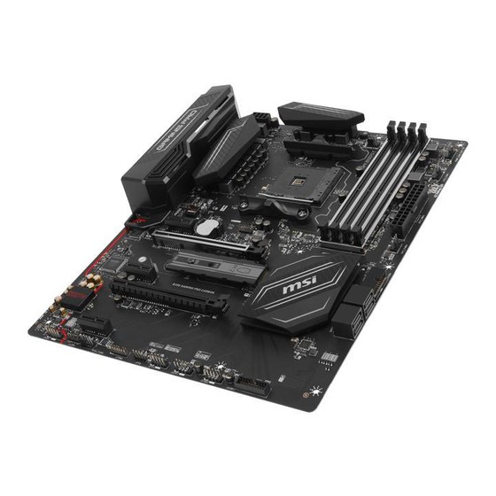
Thank you for buying the MSI
B350 GAMING PRO CARBON
motherboard. Check
®
to make sure your motherboard box contains the following items. If something is
missing, contact your dealer as soon as possible.
Drivers & Utilities
Motherboard User
Disc
Guide
Motherboard
I/O Shield
SATA Cable x2
RGB LED Extension
Cable 80cm x1
SATA Cable Labels
1
Unpacking
Advertisement
Table of Contents

Related Manuals for MSI B350 GAMING PRO CARBON


Summary of Contents for MSI B350 GAMING PRO CARBON
-
Page 1: Unpacking
Unpacking Thank you for buying the MSI B350 GAMING PRO CARBON motherboard. Check ® to make sure your motherboard box contains the following items. If something is missing, contact your dealer as soon as possible. Drivers & Utilities Motherboard User... -
Page 2: Safety Information
Safety Information The components included in this package are prone to damage from electrostatic discharge (ESD). Please adhere to the following instructions to ensure successful computer assembly. Ensure that all components are securely connected. Loose connections may cause the computer to not recognize a component or fail to start. Hold the motherboard by the edges to avoid touching sensitive components. -
Page 3: Quick Start
Quick Start Preparing Tools and Components AM4 CPU ® Thermal Paste CPU Fan DDR4 Memory Power Supply Unit Chassis SATA Hard Disk Drive Graphics Card SATA DVD Drive A Package of Screws Phillips Screwdriver Quick Start... -
Page 4: Installing A Processor
Installing a Processor https://youtu.be/Xv89nhFk1vc Quick Start... -
Page 5: Installing Ddr4 Memory
Installing DDR4 memory http://youtu.be/T03aDrJPyQs DIMMB2 DIMMB2 DIMMB1 DIMMA2 DIMMA2 DIMMA2 DIMMA1 Quick Start... -
Page 6: Connecting The Front Panel Header
Connecting the Front Panel Header http://youtu.be/DPELIdVNZUI HDD LED + Power LED + HDD LED - Power LED - Reset Switch Power Switch Reset Switch Power Switch JFP1 Reserved No Pin JFP1 HDD LED - HDD LED HDD LED + POWER LED - POWER LED POWER LED + Quick Start... -
Page 7: Installing The Motherboard
Installing the Motherboard Quick Start... -
Page 8: Installing Sata Drives
Installing SATA Drives http://youtu.be/RZsMpqxythc Quick Start... -
Page 9: Installing A Graphics Card
Installing a Graphics Card http://youtu.be/mG0GZpr9w_A Quick Start... -
Page 10: Connecting Peripheral Devices
Connecting Peripheral Devices Quick Start... -
Page 11: Connecting The Power Connectors
Connecting the Power Connectors http://youtu.be/gkDYyR_83I4 ATX_PWR1 CPU_PWR1 Quick Start... -
Page 12: Power On
Power On Quick Start... -
Page 13: Table Of Contents
Contents Unpacking ......................1 Safety Information ....................2 Quick Start ......................3 Preparing Tools and Components ................3 Installing a Processor ..................... 4 Installing DDR4 memory ..................5 Connecting the Front Panel Header ............... 6 Installing the Motherboard ..................7 Installing SATA Drives..................... - Page 14 LIVE UPDATE 6 ...................... 57 COMMAND CENTER ..................... 59 GAMING APP ......................63 RAMDISK....................... 68 X-BOOST ....................... 69 MSI SMART TOOL ....................71 GAMING LAN MANAGER ..................73 DRAGON EYE ......................75 Nahimic 2 ......................76 XSplit Gamecaster V2 ................... 80 SteelSeries Engine 3 ....................
-
Page 15: Specifications
Supports non-ECC UDIMM memory Supports ECC UDIMM memory (non-ECC mode) * 7th Gen A-series/ Athlon™ processors support up to 2400 MHz only. Please refer www.msi.com for more information on compatible memory. 1x PCIe 3.0 x16 slot (PCI_E2) RYZEN series processors support x16 speed ƒ... - Page 16 Continued from previous page ASMedia ASM2142 Chipset ® 1x USB 3.1 Gen2 (SuperSpeed USB 10Gbps) Type-C port ƒ on the back panel 1x USB 3.1 Gen2 (SuperSpeed USB 10Gbps) Type-A port ƒ on the back panel B350 Chipset ® 4x USB 3.1 Gen1 (SuperSpeed USB) ports available ƒ...
- Page 17 ACPI 5.0, PnP 1.0a, SM BIOS 3.0 Multi-language Drivers COMMAND CENTER LIVE UPDATE 6 SUPER CHARGER RAMDISK X-BOOST MSI SMART TOOL GAMING APP Software GAMING LAN MANAGER Nahimic Audio XSplit Gamecaster V2 SteelSeries Engine 3 CPU-Z MSI GAMING DRAGON EYE...
- Page 18 VR Boost VR Ready GAMING HOTKEY GAMING MOUSE Control Click BIOS 5 AMD FreeSync™ Ready AMD OverDrive™ Ready GAMING Certified SteelSeries Certified WTFast* * This offer is valid for a limited period only, for more information please visit www.msi.com Specifications...
-
Page 19: Block Diagram
Block Diagram DVI-D HDMI 2 Channel DDR4 Memory PCI Express Bus 4 x USB 3.1 Gen1 1 x M.2 Audio Jacks Realtek ALC1220 NV6795 Super I/O PCIe x1 slot P/S2 Mouse / Keyboard PCIe x1 slot PCIe x1 slot PCIe X4 PCIe x16 slot (support x4 mode) Chipset... -
Page 20: Rear I/O Panel
Rear I/O Panel Audio Ports USB 3.1 PS/2 Combo USB 3.1 Gen1 Gen2 Type-A DVI-D USB 3.1 Gen2 USB 2.0 Type-C USB 3.1 Gen1 Optical S/PDIF-Out LAN Port LED Status Table Link/ Activity LED Speed LED Status Description Status Description No link 10 Mbps connection Yellow... -
Page 21: Realtek Hd Audio Manager
Realtek HD Audio Manager After installing the Realtek HD Audio driver, the Realtek HD Audio Manager icon will appear in the system tray. Double click on the icon to launch. Device Selection Advanced Settings Jack Status Application Enhancement Main Volume Connector Strings Profiles... - Page 22 Audio jacks to headphone and microphone diagram Audio jacks to stereo speakers diagram AUDIO INPUT Audio jacks to 7.1-channel speakers diagram AUDIO INPUT Rear Front Side Center/ Subwoofer Rear I/O Panel...
-
Page 23: Overview Of Components
Overview of Components DIMMA1 SYS_FAN1 DIMMA2 CPU_FAN1 DIMMB1 Processor CPU_PWR1 DIMMB2 Socket PUMP_FAN1 SYS_FAN4 ATX_PWR1 SYS_FAN3 PCI_E1 JBAT1 PCI_E2 JUSB4 JCI1 M2_1 SATA▼1▲2 PCI_E3 SATA▼3▲4 PCI_E4 PCI_E5 JAUD1 JUSB3 JLED1 JUSB2 SYS_FAN2 JUSB1 JFP1 JTPM1 JFP2 Overview of Components... - Page 24 Component Contents Port Name Port Type Page CPU_FAN1, PUMP_FAN1, SYS_FAN1~4 Fan Connectors CPU_PWR1, ATX_PWR1 Power Connectors DIMMA1, DIMMA2, DIMMB1, DIMMB2 DIMM Slots JAUD1 Front Audio Connector Clear CMOS (Reset BIOS) JBAT1 Jumper JCI1 Chassis Intrusion Connector JFP1, JFP2 Front Panel Connectors JLED1 RGB LED strip connector JTPM1...
-
Page 25: Processor Socket
This motherboard is designed to support overclocking. Before attempting to overclock, please make sure that all other system components can tolerate overclocking. Any attempt to operate beyond product specifications is not recommended. MSI does not guarantee the damages or risks caused by ®... -
Page 26: Dimm Slots
Due to AM4 processor/memory controller official specification limitation, the frequency of memory modules may operate lower than the marked value under the default state. Please refer www.msi.com for more information on compatible memory. Overview of Components... -
Page 27: Pci_E1~5: Pcie Expansion Slots
PCI_E4: PCIe 2.0 x4 PCI_E5: PCIe 2.0 x1 Important If you install a large and heavy graphics card, you need to use a tool such as MSI Gaming Series Graphics Card Bolster to support its weight to prevent deformation of the slot. -
Page 28: M2_1: M.2 Slot (Key M)
M2_1: M.2 Slot (Key M) Video Demonstration Watch the video to learn how to use M.2 Shield. https://youtu.be/NwtQBpkUazs Installing M.2 module Remove the screw from the base screw. Put the screw in the notch on the trailing edge of your M.2 Remove the base screw. -
Page 29: Sata1~4: Sata 6Gb/S Connectors
SATA1~4: SATA 6Gb/s Connectors These connectors are SATA 6Gb/s interface ports. Each connector can connect to one SATA device. SATA2 SATA1 SATA4 SATA3 Important Please do not fold the SATA cable at a 90-degree angle. Data loss may result during transmission otherwise. -
Page 30: Cpu_Pwr1, Atx_Pwr1: Power Connectors
CPU_PWR1, ATX_PWR1: Power Connectors These connectors allow you to connect an ATX power supply. CPU_PWR1 Ground +12V Ground +12V Ground +12V Ground +12V +3.3V +3.3V +3.3V -12V Ground Ground PS-ON# Ground Ground Ground ATX_PWR1 Ground Ground PWR OK 5VSB +12V +12V +3.3V Ground... -
Page 31: Jusb1~2: Usb 2.0 Connectors
JUSB1~2: USB 2.0 Connectors These connectors allow you to connect USB 2.0 ports on the front panel. USB0- USB1- USB0+ USB1+ Ground Ground No Pin Important Note that the VCC and Ground pins must be connected correctly to avoid possible damage. -
Page 32: Cpu_Fan1, Pump_Fan1, Sys_Fan1~4: Fan Connectors
CPU_FAN1, PUMP_FAN1, SYS_FAN1~4: Fan Connectors Fan connectors can be classified as PWM (Pulse Width Modulation) Mode or DC Mode. PWM Mode fan connectors provide constant 12V output and adjust fan speed with speed control signal. DC Mode fan connectors control fan speed by changing voltage. When you plug a 3-pin (Non-PWM) fan to a fan connector in PWM mode, the fan speed will always maintain at 100%, which might create a lot of noise. -
Page 33: Jaud1: Front Audio Connector
JAUD1: Front Audio Connector This connector allows you to connect audio jacks on the front panel. MIC L Ground MIC R Head Phone R MIC Detection SENSE_SEND No Pin Head Phone L Head Phone Detection JCI1: Chassis Intrusion Connector This connector allows you to connect the chassis intrusion switch cable. Normal Trigger the chassis intrusion event... -
Page 34: Jtpm1: Tpm Module Connector
JTPM1: TPM Module Connector This connector is for TPM (Trusted Platform Module). Please refer to the TPM security platform manual for more details and usages. LPC Clock 3V Standby power LPC Reset 3.3V Power LPC address & data pin0 Serial IRQ LPC address &... -
Page 35: Jled1: Rgb Led Strip Connector
JLED1: RGB LED strip connector This connector allows you to connect the extended 5050 RGB LED strips. +12V 5050 LED strip Extension cable JLED1 Video Demonstration Watch the video to learn how to install 5050 RGB LED strips to RGB LED connector. -
Page 36: Onboard Leds
Onboard LEDs DIMM LEDs These LEDs indicate the memory modules are installed. GPU LED This LED indicates the CPU’ s iGPU is not detected and you need to install a graphic card. DIMM LEDs GPU LED PCIe x16 slot LEDs These LEDs indicate the PCIe x16 slots status. -
Page 37: Bios Setup
BIOS Setup The default settings offer the optimal performance for system stability in normal conditions. You should always keep the default settings to avoid possible system damage or failure booting unless you are familiar with BIOS. Important BIOS items are continuously update for better system performance. Therefore, the description may be slightly different from the latest BIOS and should be for reference only. -
Page 38: Resetting Bios
Updating BIOS Updating BIOS with M-FLASH Before updating: Please download the latest BIOS file that matches your motherboard model from MSI website. And then save the BIOS file into the USB flash drive. Updating BIOS: Press Del key to enter the BIOS Setup during POST. -
Page 39: Ez Mode
EZ Mode At EZ mode, it provides the basic system information and allows you to configure the basic setting. To configure the advanced BIOS settings, please enter the Advanced Mode by pressing the Setup Mode switch or F7 function key. Screenshot A-XMP switch Setup Mode switch... - Page 40 Information display - click on the CPU, Memory, Storage, Fan Info and Help buttons on left side to display related information. Function buttons - enable or disable the LAN Option ROM, HD audio controller, AHCI, RAID, CPU Fan Fail Warning Control, Windows 10 WHQL Support and BIOS Log Review by clicking on their respective button.
-
Page 41: Advanced Mode
Advanced Mode Press Setup Mode switch or F7 function key can switch between EZ Mode and Advanced Mode in BIOS setup. Screenshot A-XMP switch Setup Mode switch Search Language System information GAME BOOST switch Boot device priority bar BIOS menu BIOS menu selection selection... -
Page 42: Settings
SETTINGS System Status System Date Sets the system date. Use tab key to switch between date elements. The format is <day> <month> <date> <year>. <day> Day of the week, from Sun to Sat, determined by BIOS. Read-only. <month> The month from Jan. through Dec. <date>... - Page 43 fPower LED [Blinking] Sets shining behaviors of the onboard Power LED. [Dual Color] The power LED turns to another color to indicate the S3 state. [Blinking] The power LED blinks to indicate the S3 state. Integrated Peripherals Sets integrated peripherals' parameters, such as LAN, HDD, USB and audio. Press Enter to enter the sub-menu.
- Page 44 fExternal SATA 6Gb/s Controller Mode [AHCI] Sets the operation mode of the external SATA controller. [Disabled] Disables the SATA function. [IDE] Specify the IDE mode for SATA storage devices. [AHCI] Specify the AHCI mode for SATA storage devices. AHCI (Advanced Host Controller Interface) offers some advanced features to enhance the speed and performance of SATA storage device, such as Native Command Queuing (NCQ) and hot-plugging.
- Page 45 fRestore after AC Power Loss [Power Off] Sets the system behaviors while encountering the AC power loss. [Power Off] Leaves the system in power off state after restoring AC power. [Power On] Boot up the system after restoring AC power. [Last State] Restores the system to the previous state (power on/ power off) before AC power loss.
- Page 46 fDate (of month) Alarm/ Time (hh:mm:ss) Alarm Sets RTC alarm date/ Time. If Resume By RTC Alarm is set to [Enabled], the system will automatically resume (boot up) on a specified date/hour/minute/second in these fields (using the + and - keys to select the date & time settings). fResume By PCI-E Device [Disabled] Enables or disables the wake up function of installed PCI-E expansion cards, integrated LAN controllers or USB devices which are supported by third party...
-
Page 47: Boot
Boot Sets the sequence of system boot devices. Full Screen Logo Display [Enabled] Enables or disables to show the full screen logo while system POST. [Enabled] Shows the logo in full screen. [Disabled] Shows the POST messages. Bootup NumLock State [On] Select the keyboard NumLock state upon bootup. - Page 48 Password Clear [Enabled] Enables or disables the clear CMOS behavior to clear a set password. [Enabled] The password will be erased after clear CMOS. [Disabled] The password will always be kept. Important When selecting the Administrator / User Password items, a password box will appear on the screen.
-
Page 49: Save & Exit
Save & Exit Discard Changes and Exit Exit BIOS setup without saving any change. Save Changes and Reboot Save all changes and reboot the system. Save Changes Save current changes. Discard Changes Discard all changes and restore to the previous values. Restore Defaults Restore or load all default values. - Page 50 Important Overclocking your PC manually is only recommended for advanced users. Overclocking is not guaranteed, and if done improperly, it could void your warranty or severely damage your hardware. If you are unfamiliar with overclocking, we advise you to use GAME BOOST function for easy overclocking.
- Page 51 Advanced DRAM Configuration (optional) Press Enter to enter the sub-menu. User can set the memory timing for each/ all memory channel. The system may become unstable or unbootable after changing memory timing. If it occurs, please clear the CMOS data and restore the default settings.
- Page 52 CPU Memory Changed Detect [Enabled]* Enables or disables the system to issue a warning message during boot when the CPU or memory has been replaced. [Enabled] The system will issue a warning message during boot and then you have to load the default settings for new devices. [Disabled] Disables this function and keeps the current BIOS settings.
-
Page 53: M-Flash
M-FLASH provides the way to update BIOS with a USB flash drive. Please download the latest BIOS file that matches your motherboard model from MSI website, save the BIOS file into your USB flash drive. And then follow the steps below to update BIOS. -
Page 54: Oc Profile
OC PROFILE Overclocking Profile 1/ 2/ 3/ 4/ 5/ 6 Overclocking Profile 1/ 2/ 3/ 4/ 5/ 6 management. Press Enter to enter the sub-menu. fSet Name for Overclocking Profile 1/ 2/ 3/ 4/ 5/ 6 Name the current overclocking profile. fSave Overclocking Profile 1/ 2/ 3/ 4/ 5/ 6 Save the current overclocking profile. -
Page 55: Hardware Monitor
HARDWARE MONITOR Temperature & Speed Fan Manage Setting Buttons Voltage display Temperature & Speed Shows the current CPU temperature, system temperature and fans' speeds. Fan Manage PWM - allows you to select the PWM mode for fan operation. ƒ DC - allows you to select the DC mode for fan operation. ƒ... -
Page 56: Software Description
7/ 10 disc into your optical drive. ® Note: Due to chipset limitation, during the Windows 7 installation process, USB optical drives or USB flash drives are not supported. You can use MSI Smart Tool to install Windows ® Press the Restart button on the computer case. -
Page 57: Live Update 6
LIVE UPDATE 6 LIVE UPDATE 6 is an application for the MSI system to scan and download the latest ® drivers, BIOS and utilities. With LIVE UPDATE 6, you don’ t need to search the drivers on websites, and don’ t need to know the models of motherboard and graphics cards. - Page 58 Select the Live Update tab. Choose Automatic scan, system will automatically scan all the items and search for the latest update files. Or you can choose Manual scan and select the items you wish to scan. Click the Scan button at the bottom. It may take several moments to complete the process.
-
Page 59: Command Center
COMMAND CENTER COMMAND CENTER is an user-friendly software and exclusively developed by MSI, helping users to adjust system settings and monitor status under OS. With the help of COMMAND CENTER, making it possible to achieve easier and efficient monitoring process and adjustments than that under BIOS. In addition, the COMMAND CENTER can be a server for mobile remote control application. - Page 60 CPU Fan CPU Fan control panel provides Smart mode and Manual Mode. You can switch the control mode by clicking the Smart Mode and Manual Mode buttons on the top of the CPU Fan control panel. Manual Mode - allows you to manually control the CPU fan speed by percentage.
- Page 61 GAME BOOST GAME BOOST provides a specified CPU frequency for overclocking the CPU. Option Buttons - Advanced When click the Advanced button, The Voltage, Fan ,DRAM and Sensor icons will appear. Voltage - allows you to adjust advanced voltage values of CPU and chipset. Fan - allows you to control the system fans speed.
- Page 62 Find the IP address on the SoftAP Management Setting area, and enter the IP address on your MSI COMMAND CENTER APP to link your system. ® Press Refresh on the MSI COMMAND CENTER APP to verify that monitoring and ® OC functions are working properly.
-
Page 63: Gaming App
Connect your android device and motherboard to the same local area network. Run MSI GAMING APP APP on your android device. ® Press the Remote Control Setting icon on the MSI GAMING APP APP to find the ® paired device Name you set in the Remote Control Setting panel. - Page 64 LED function allows you to control LED lights on your motherboard. ON/OFF LED Area Selection LED ON/OFF - allows you to turn ON/ OFF the LED function. LED Area Selection - separately controls each segment of LEDs on your motherboard and graphics cards. LED effects - switches LEDs on or off.
- Page 65 Eye Rest Eye Rest allows you to optimize the display on your monitor. EyeRest - reduces blue-light of your LED backlit screen, in order to protect your eyes. Gaming - automatically increases contrast ratio of your screen. Movie - automatically increases dynamic contrast ratio of your screen. Customize - allows you to adjust gamma, contrast and color balance for your screen.
- Page 66 Login Keys - provides hotkey login function. ƒ MSI Smart Keys - allows you to define hotkeys for MSI Smart Keys. ƒ Hotkey Manager - allows you to create, edit and delete hotkeys. Current Hotkeys - shows all existing hotkeys.
- Page 67 Mouse Master Mouse Master provides mouse macro function. You can also use it to change DPI of your mouse. DPI Setting Delay Time Default Button Macro Hot Key DPI Hot Key Mouse Action Action List Test Area Edit Buttons Clear Button Load Button Save Button Delay Time - allows you to apply a delay time in mouse macro.
-
Page 68: Ramdisk
RAMDISK RAMDISK creates a virtual RAM drive using the available memory in your computer, the performance of the RAMDISK is faster than an SSD and hard drive. RAMDISK allows you to store any temporary information on it. Furthermore, using the RAMDISK will extend your SSD’... -
Page 69: X-Boost
X-BOOST The MSI X-BOOST allows you to select the system performance mode to meet your current system environment or support faster storage access speed for your external storage or memory cards. Easy In Easy page, you can select one system performance mode to meet the current system environment. - Page 70 Setting - enables or disables Run X-BOOST when windows starts. Important Please note that you can only select one mode at a time from Easy or Advance page as MSI X-BOOST function. The improved transfer rate/ access speed will vary with the USB/ storage device. Software Description...
-
Page 71: Msi Smart Tool
MSI SMART TOOL MSI SMART TOOL is a convenient tool that can help you to create your Windows installation USB flash drive with USB 3.0 drivers, and it can also create a super RAID. Main menu After installing and activating MSI SMART TOOL, it will display a main menu for you to choose Win7 Smart Tool or Super RAID. - Page 72 Super RAID This utility allows you to create a Super RAID in Windows system. To create a Super RAID: Use checkboxs to select the disks you want included in your RAID. Choose Speed Up or Backup for RAID type. y Speed Up = RAID0 y Backup = RAID1 Click Start.
-
Page 73: Gaming Lan Manager
GAMING LAN MANAGER GAMING LAN MANAGER is an utility for traffic shaping for the Windows 7/ 10. It can keep your internet fast during heavy upload/ download and improve your ping for online games. If your motherboard has a Wi-Fi module, GAMING LAN MANAGER provides virtual access point function for traffic shaping for your mobile devices. - Page 74 Speed Testing The speed testing is used to optimize bandwidth usage. To test the Upload and Down- load speed, please follow the steps below: Click the Network Test block in GAMING LAN MANAGER. Click Test Network Speed button. The test takes several minutes to test your network speed.
-
Page 75: Dragon Eye
DRAGON EYE DRAGON EYE allows you to watch game guides, tutorials, live match or tournament stream while gaming. In game, you can use hotkeys to control/adjust the settings of DRAGON EYE. Size Settings Position Settings On / Off Switch Help Transparency Settings Video List Hotkeys Information... -
Page 76: Nahimic 2
HD Audio Recorder2 and Sound Tracker. Installation and Update Nahimic 2 is included in the audio driver. If you need to install it or update it, please use the Driver Disc with your motherboard or download the driver from MSI’ s official website. Audio Tab From this tab, you can access all of Nahimic 2’... - Page 77 Smart Loudness - maintains a constant volume for all elements of the audio ƒ experience to making them all sound softer, balanced or louder. Voice Clarity - boosts the speech in movies, video games and incoming ƒ communication from +0 through +12 dB (0 to 100%). Reset Button - restores the current profile to its default values.
- Page 78 Device properties - allows you to boost the volume and modify the left/ right ƒ balance of microphone. Clicks on this button and a device properties panel will show. Microphone Loopback - turns the microphone loopback On/Off. In order to avoid any feedback (Larsen effect).
- Page 79 Control Page - by clicking the arrow button, you can access the control page. Audio Launchpad ON/OFF - switches the Audio Launchpad on or off. ƒ HD Audio Recorder 2 - The HD Audio Recorder 2 is, by default, automatically ƒ...
-
Page 80: Xsplit Gamecaster V2
Login button. Important When starting XSplit Gamecaster V2 on select MSI gaming laptops, all-in ones or on ® machines that contain select MSI motherboards or graphics cards, you will receive ®... - Page 81 Learning stream and record Refer to the Start page of XSplit Gamecaster V2 to learn how to stream and record your gameplay. Tool Tip When you click the question mark next to a feature name on the panel, a tooltip will show, describing the particular function of that item.
- Page 82 Share Button - If you authorize your Facebook, Twitter, and/or Google+ accounts, you can quickly share your stream URL and status update within the overlay. Annotations - This feature of XSplit Gamecaster V2 allows you to draw directly onto your game play. You can activate annotation mode by clicking on the pencil button in the overlay.
- Page 83 Microphone Settings - In this region, you can select your desired microphone. What is shown in the list depends on what you have connected to your PC. If you don’ t see your desired device in the list, please make sure that it is detected and it is not disabled in your recording devices list in the Windows Sound Menu (Start >...
-
Page 84: Steelseries Engine 3
SteelSeries Engine 3 SteelSeries Engine 3 is a unified platform built to support all of SteelSeries products. It can deploy your saved device settings automatically when switching between your favorite games or applications. After installation the SteelSeries Engine background processes will start and the interface will open automatically. - Page 85 Configuring Your Devices You can custom configurations for SteelSeries devices in their Configuration Windows. The top left displays the name of the configuration you are viewing, the body features widgets for customizing various functions of the device, and at the bottom are Save/ Revert buttons, a Live Preview toggle, and a button to open/close the collapsible Configuration List Panel.
-
Page 86: Cpu-Z
CPU-Z CPU-Z is an utility that gathers information on some of the main devices of your system. CPU Tab - shows processor name, code name, package, specification, instructions sets, core speed and cache levels. Caches Tab - shows extended information related to the cache capabilities. Mainboard Tab - shows motherboard manufacturer, model name, chipset, BIOS version and graphic interface. -
Page 87: Troubleshooting
Troubleshooting Lost BIOS password Before sending the motherboard for RMA repair, try to go over troubleshooting Clear the CMOS, but that will cause guide first to see if your got similar you to lose all customized settings in symptoms as mentioned below. the BIOS. -
Page 88: Regulatory Notices
EU REACH Regulation (Regulation EC No. 1907/2006 of the European Parliament and the This device complies with part 15 of the FCC Rules. Council), MSI provides the information of chemical Operation is subject to the following two conditions: substances in products at: (1) This device may not cause harmful interference, and http://www.msi.com/html/popup/csr/evmtprtt_pcm. - Page 89 MSI will comply with the product take entregar a una empresa autorizada para la recogida de back requirements at the end of life of MSI-branded estos residuos.
- Page 90 MSI si adeguerà a tale Direttiva ritirando tutti i prodotti marchiati MSI che sono stati venduti all’interno dell’Unione Europea alla fine del loro ciclo di vita.
- Page 91 Alternatively, please try the following help resources for further guidance. y Visit the MSI website for technical guide, BIOS updates, driver updates, and other information: http://www.msi.com y Register your product at: http://register.msi.com...
Need help?
Do you have a question about the B350 GAMING PRO CARBON and is the answer not in the manual?
Questions and answers