Table of Contents
Advertisement
Thank you for purchasing the MSI
PRO-VDH
motherboard. This User Guide gives information
about board layout, component overview, BIOS setup and
software installation.
Contents
Safety Information ........................................................................................... 2
Specifications ................................................................................................... 3
Rear I/O Panel ................................................................................................. 6
LAN Port LED Status Table ................................................................................6
Overview of Components ................................................................................ 7
CPU Socket .........................................................................................................8
DIMM Slots .........................................................................................................9
PCI_E1~3: PCIe Expansion Slots........................................................................9
JFP1, JFP2: Front Panel Connectors ...............................................................10
SATA1~4: SATA 6Gb/s Connectors ...................................................................10
M2_1: M.2 Slot (Key M) .....................................................................................11
ATX_PWR1, CPU_PWR1: Power Connectors ...................................................11
JUSB1~2: USB 2.0 Connectors ........................................................................12
JUSB3: USB 3.1 Gen1 Connector .....................................................................12
CPU_FAN1, SYS_FAN1~2: Fan Connectors .....................................................13
JTPM1: TPM Module Connector.......................................................................14
JCI1: Chassis Intrusion Connector ..................................................................14
JAUD1: Front Audio Connector ........................................................................15
JCOM1: Serial Port Connector .........................................................................15
JLPT1: Parallel Port Connector .......................................................................15
JBAT1: Clear CMOS (Reset BIOS) Jumper .......................................................16
EZ Debug LED: Debug LED indicators .............................................................16
JLED1: RGB LED strip connector ....................................................................16
BIOS Setup ..................................................................................................... 17
Entering BIOS Setup.........................................................................................17
Resetting BIOS .................................................................................................18
Updating BIOS ..................................................................................................18
Software Description ..................................................................................... 19
Installing Drivers ..............................................................................................19
Installing Utilities .............................................................................................20
®
B350M PRO-VDH/ A320M
®
®
1
Contents
Advertisement
Table of Contents

Related Manuals for MSI B350M PRO-VDH


Summary of Contents for MSI B350M PRO-VDH
-
Page 1: Table Of Contents
Thank you for purchasing the MSI B350M PRO-VDH/ A320M ® PRO-VDH motherboard. This User Guide gives information about board layout, component overview, BIOS setup and software installation. Contents Safety Information ................... 2 Specifications ....................3 Rear I/O Panel ....................6 LAN Port LED Status Table ................6... -
Page 2: Safety Information
Safety Information The components included in this package are prone to damage from electrostatic discharge (ESD). Please adhere to the following instructions to ensure successful computer assembly. Ensure that all components are securely connected. Loose connections may cause the computer to not recognize a component or fail to start. Hold the motherboard by the edges to avoid touching sensitive components. -
Page 3: Specifications
Specifications Supports AMD RYZEN series processors and 7th Gen ® A-series/ Athlon™ processors for Socket AM4 B350 chipset (B350M PRO-VDH) ® Chipset A320 chipset (A320M PRO-VDH) ® 4x DDR4 memory slots, support up to 64GB Supports DDR4 1866/ 2133/ 2400/ 2667(OC)/ 2933(OC)/ ƒ... - Page 4 ® 4x USB 3.1 Gen1 (SuperSpeed USB) Type-A ports on the back panel 1x PS/2 keyboard/ mouse combo port 4x USB 2.0 Type-A ports (B350M PRO-VDH) 2x USB 2.0 Type-A ports (A320M PRO-VDH) 1x VGA port Back Panel 1x DVI-D port Connectors 1x HDMI™...
- Page 5 BIOS Features ACPI 5.0, SM BIOS 3.0 Multi-language Drivers SUPER CHARGER COMMAND CENTER LIVE UPDATE 6 MYSTIC LIGHT NETWORK GENIE Software MSI SMART TOOL X-BOOST RAMDISK Norton Security ™ Google Chrome ,Google Toolbar, Google Drive ™ CPU-Z MSI GAMING Specifications...
-
Page 6: Rear I/O Panel
Rear I/O Panel (B350M PRO-VDH only) Line-in Line-out USB 2.0 PS/2 Mic in DVI-D USB 2.0 USB 3.1 Gen1 LAN Port LED Status Table Link/ Activity LED Speed LED Status Description Status Description 10 Mbps connection No link Green 100 Mbps connection... -
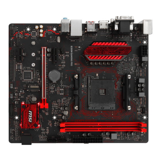
Page 7: Overview Of Components
Overview of Components DIMMA1 CPU_PWR1 CPU_FAN1 DIMMA2 SYS_FAN1 CPU Socket DIMMB1 DIMMB2 EZ Debug LED ATX_PWR1 SATA1 SATA2 PCI_E1 M2_1 SATA▼3▲4 PCI_E2 PCI_E3 JBAT1 JCI1 JFP2 JAUD1 JFP1 JUSB3 JCOM1 JUSB2 JLED1 JUSB1 JTPM1 JLPT1 SYS_FAN2 Overview of Components... -
Page 8: Cpu Socket
CPU Socket Please install the CPU into the CPU socket as shown below. Important When changing the processor, the system configuration could be cleared and reset BIOS to default values due to the AM4 processor’ s architecture. Always unplug the power cord from the power outlet before installing or removing the CPU. -
Page 9: Dimm Slots
If you install a large and heavy graphics card, you need to use a tool such as MSI Gaming Series Graphics Card Bolster to support its weight to prevent deformation of the slot. -
Page 10: Jfp1, Jfp2: Front Panel Connectors
JFP1, JFP2: Front Panel Connectors These connectors connect to the switches and LEDs on the front panel. HDD LED + Power LED + HDD LED - Power LED - Reset Switch Power Switch JFP1 Reset Switch Power Switch Reserved No Pin HDD LED - HDD LED HDD LED +... -
Page 11: M2_1: M.2 Slot (Key M)
M2_1: M.2 Slot (Key M) Please install the M.2 solid-state drive (SSD) into the M.2 slot as shown below. 30° ATX_PWR1, CPU_PWR1: Power Connectors These connectors allow you to connect an ATX power supply. +3.3V +3.3V +3.3V -12V Ground Ground PS-ON# Ground Ground... -
Page 12: Jusb1~2: Usb 2.0 Connectors
JUSB1~2: USB 2.0 Connectors These connectors allow you to connect USB 2.0 ports on the front panel. USB0- USB1- USB0+ USB1+ Ground Ground No Pin Important Note that the VCC and Ground pins must be connected correctly to avoid possible damage. -
Page 13: Cpu_Fan1, Sys_Fan1~2: Fan Connectors
CPU_FAN1, SYS_FAN1~2: Fan Connectors Fan connectors can be classified as PWM (Pulse Width Modulation) Mode or DC Mode. PWM Mode fan connectors provide constant 12V output and adjust fan speed with speed control signal. DC Mode fan connectors control fan speed by changing voltage. -
Page 14: Jtpm1: Tpm Module Connector
JTPM1: TPM Module Connector This connector is for TPM (Trusted Platform Module). Please refer to the TPM security platform manual for more details and usages. LPC Clock 3V Standby power LPC Reset 3.3V Power LPC address & data pin0 Serial IRQ LPC address &... -
Page 15: Jaud1: Front Audio Connector
JAUD1: Front Audio Connector This connector allow you to connect audio jacks on the front panel. MIC L Ground MIC R Head Phone R MIC Detection SENSE_SEND No Pin Head Phone L Head Phone Detection JCOM1: Serial Port Connector This connector allows you to connect the optional serial port with bracket. SOUT Ground No Pin... -
Page 16: Jbat1: Clear Cmos (Reset Bios) Jumper
JBAT1: Clear CMOS (Reset BIOS) Jumper There is CMOS memory onboard that is external powered from a battery located on the motherboard to save system configuration data. If you want to clear the system configuration, set the jumpers to clear the CMOS memory. Keep Data Clear CMOS/ Reset (default) -
Page 17: Bios Setup
BIOS Setup The default settings offer the optimal performance for system stability in normal conditions. You should always keep the default settings to avoid possible system damage or failure booting unless you are familiar with BIOS. Important BIOS items are continuous update for better system performance. Therefore, the description may be slightly different from the latest BIOS and should be held for reference only. -
Page 18: Resetting Bios
Updating BIOS Updating BIOS with M-FLASH Before updating: Please download the latest BIOS file that matches your motherboard model from MSI website. And then save the BIOS file into the USB flash drive. Updating BIOS: Press Del key to enter the BIOS Setup during POST. -
Page 19: Software Description
Note: Due to chipset limitation, during the Windows 7 installation process, USB ® optical drives and USB pen drives are not supported. You can use MSI Smart Tool to install Windows ® Press the Restart button on the computer case. -
Page 20: Installing Utilities
Installing Utilities Before you install utilities, you must complete drivers installation. Insert MSI Driver Disc into your optical drive. ® The installer will automatically appear. Click Utilities tab. Select the utilities you want to install. Click Install button. The utilities installation will then be in progress, after it has finished it will prompt you to restart.
Need help?
Do you have a question about the B350M PRO-VDH and is the answer not in the manual?
Questions and answers