Table of Contents
Advertisement
Available languages
Available languages
Quick Links
Operator's Manual
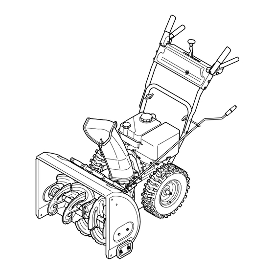
24" SNOW THROWER
Model No. 247.881722
CAUTION: Before using this product,
read this manual and follow all safety
rules and operating instructions.
Sears Brands Management Corporation, Hoffman Estates, IL 60179, U.S.A.
Visit our website: www.craftsman.com
• SAFETY
• ASSEMBLY
• OPERATION
• MAINTENANCE
• ESPAÑOL
Form No. 769-10905A
(May 17, 2016)
Advertisement
Chapters
Table of Contents

Related Manuals for Craftsman 247.881722


Summary of Contents for Craftsman 247.881722
- Page 1 Operator’s Manual 24” SNOW THROWER Model No. 247.881722 • SAFETY • ASSEMBLY • OPERATION • MAINTENANCE CAUTION: Before using this product, • ESPAÑOL read this manual and follow all safety rules and operating instructions. Sears Brands Management Corporation, Hoffman Estates, IL 60179, U.S.A.
-
Page 2: Table Of Contents
WITH PROOF OF SALE, a defective product will receive free repair or replacement at option of seller. For warranty coverage details to obtain free repair or replacement, visit the web page: www.craftsman.com/warranty This warranty covers ONLY defects in material and workmanship. Warranty coverage does NOT include: •... - Page 3 SAFETY INSTRUCTIONS WARNING DANGER This symbol points out important safety instructions which, if not This machine was built to be operated according to the safe operation followed, could endanger the personal safety and/or property of practices in this manual. As with any type of power equipment, yourself and others.
- Page 4 SAFETY INSTRUCTIONS • To reduce fire hazards, keep machine free of grass, leaves, or other debris • Use only attachments and accessories approved by the manufacturer (e.g. build-up. Clean up oil or fuel spillage and remove any fuel soaked debris. wheel weights, tire chains, cabs etc.).
- Page 5 SAFETY INSTRUCTIONS • Check fuel line, tank, cap, and fittings frequently for cracks or leaks. Replace if necessary. • Do not crank engine with spark plug removed. • According to the Consumer Products Safety Commission (CPSC) and the U.S. Environmental Protection Agency (EPA), this product has an Average Useful Life of seven (7) years, or 60 hours of operation.
- Page 6 SAFETY INSTRUCTIONS SAFETY SYMBOLS This page depicts and describes safety symbols that may appear on this product. Read, understand, and follow all instructions on the machine before attempting to assemble and operate. Symbol Description READ THE OPERATOR’S MANUAL(S) Read, understand, and follow all instructions in the manual(s) before attempting to assemble and operate.
- Page 7 This page left intentionally blank.
-
Page 8: Assembly
ASSEMBLY NOTE: References to right or left side of the snow thrower are determined from behind the unit in the operating position (standing directly behind the snow thrower, facing the handle panel). Removing From Carton Cut the corners of the carton and lay the sides flat on the ground. Remove and discard all packing inserts. - Page 9 ASSEMBLY Pivot flange keepers out and position the chute assembly over the base. See Figure 4. Close the flange keepers to secure the chute assembly to the chute base. See Figure 5. The flange keepers will click into place when properly secure. NOTE: If the flange keepers will not easily click into place, use the palm of your hand to apply swift, firm pressure to the back of each.
- Page 10 ASSEMBLY Set-Up Chute Clean-Out Tool A chute clean-out tool is fastened to the top of the auger housing with a mounting clip. See Figure 7. The tool is designed to clear a chute assembly of ice and snow. This item is fastened with a cable tie at the factory. Cut the cable tie before operating the snow thrower.
-
Page 11: Operation
OPERATION Chute The distance snow is thrown can be adjusted by changing the angle of the upper chute. To do so: Stop the engine by removing the ignition key and loosen the plastic wing knob found on the left side of the chute assembly. Pivot the chute upward or downward before retightening the wing knob. - Page 12 Your snow thrower has two reverse (R) speeds. Position one (1) is the slower and position two (2) is the faster. Meets ANSI Safety Standards Craftsman Snow Throwers conform to the safety standard of the American National Standards Institute (ANSI).
- Page 13 OPERATION Throttle Control Drive Control/ Auger Control Lock DRIVE CONTROL The throttle control is located on the rear of the engine. It regulates the speed of the engine and will shut off the engine when moved into the STOP position. Primer Depressing the primer forces fuel directly into the engine’s carburetor to aid in cold-weather starting.
- Page 14 OPERATION Clean-Out Tool • Do not overfill the fuel tank. After refueling, make sure the tank cap is closed properly and securely. WARNING • Be careful not to spill fuel when refueling. Spilled fuel or fuel vapor may ignite. If any fuel is spilled, make sure the area is dry before starting the Never use your hands to clear a clogged chute assembly.
- Page 15 OPERATION To Engage Drive Move throttle control to FAST (rabbit) position. With the throttle control in the Fast (rabbit) position, move shift lever Move choke to the CHOKE position (cold engine start). If engine is into one of the six forward (F) positions or two reverse (R) positions. Select a warm, place choke in RUN position.
-
Page 16: Service &Maintenance
SERVICE AND MAINTENANCE MAINTENANCE SCHEDULE Follow the maintenance schedule given below. This chart describes service WARNING guidelines only. Use the Service Log column to keep track of completed Before performing any type of maintenance/service, disengage all controls maintenance tasks. To locate the nearest Sears Service Center or to schedule service, and stop the engine. - Page 17 SERVICE AND MAINTENANCE Refill with the recommended oil and check the oil level. See Recommended Oil Usage chart. The engine’s oil capacity is 20 oz. Synthetic 0W-30 5W-30 -40º -20º 0º 20º 40º -30º -20º -10º 0º Oil Drain Plug CAUTION DO NOT use nondetergent oil or 2-stroke engine oil.
- Page 18 SERVICE AND MAINTENANCE CAUTION The spark plug must be tightened securely. A loose spark plug can become very hot and can damage the engine. Lubrication Gear Shaft The gear (hex) shaft should be lubricated at least once a season or after every 25 hours of operation.
- Page 19 SERVICE AND MAINTENANCE Adjustments Shift Cable If the full range of speeds (forward and reverse) cannot be achieved, refer to the figure to the right and adjust the shift cable as follows: Place the shift lever in the fastest forward speed position (F6). Loosen the hex nut on the shift cable index bracket.
- Page 20 SERVICE AND MAINTENANCE Auger Control Refer to page 11 in the Assembly section for instructions on adjusting the auger control cable. Skid Shoes Refer to page 10 in the Assembly section for instructions on adjusting the skid shoes. Belt Replacement Auger Belt To remove and replace your snow thrower’s auger belt, proceed as follows: To prevent spillage, remove all fuel from tank by running engine until it...
- Page 21 SERVICE AND MAINTENANCE Loosen and remove the shoulder screw which acts as a belt keeper. Refer to Figure 27. Remove the belt from around the auger pulley, and slip the belt between the support bracket and the auger pulley. See Figure 28. NOTE: Engaging the auger control will ease removal and reinstallation of the belt.
- Page 22 SERVICE AND MAINTENANCE Carefully remove the hex nut and washer which secures the hex shaft to the snow thrower frame and lightly tap the shaft’s end to dislodge the ball bearing from the right side of the frame. See Figure 30. NOTE: Be careful not to damage the threads on the shaft.
-
Page 23: Off-Season Storage
OFF-SEASON STORAGE If the snow thrower will not be used for 30 days or longer, or if the end of the snow season, the equipment needs to be stored properly. Follow storage instructions below to ensure top performance from the snow thrower for future use. Preparing Engine Preparing Snow Thrower Engines stored over 30 days need to be drained of fuel to prevent deterioration and... -
Page 24: Troubleshooting
TROUBLESHOOTING WARNING Disconnect the spark plug wire and ground it against the engine to prevent unintended starting. Before performing any type of maintenance/service, disengage all controls and stop the engine. Wait until all moving parts have come to a complete stop. Always wear safety glasses during operation or while performing any adjustments or repairs. - Page 25 TROUBLESHOOTING Problem Cause Remedy Unit fails to discharge snow 1. Chute assembly clogged. 1. Stop engine immediately and disconnect spark plug wire. Clean chute assembly and inside of auger housing with clean-out tool. 2. Foreign object lodged in auger. 2. Stop engine immediately and disconnect spark plug wire. Remove object from auger with clean-out tool.
- Page 26 FEDERAL and/or CALIFORNIA EMISSION CONTROL WARRANTY STATEMENT YOUR WARRANTY RIGHTS AND OBLIGATIONS MTD Consumer Group Inc, the United States Environmental Protection Agency (EPA), and for those products certified for sale in the state of California, the California Air Resources Board (CARB) are pleased to explain the emission control system (ECS) warranty on your 2015- 2016 small off-road spark-ignited engine and equipment (outdoor equipment).
- Page 27 Add-on or modified parts that are not exempted by the Air Resources Board may not be used. The use of any non-exempted add-on or modified parts by the ultimate purchaser will be grounds for disallowing a warranty claim. MTD Consumer Group Inc will not be liable to warrant failures of warranted parts caused by the use of a non-exempted add-on or modified part.
-
Page 28: Repair Protection Agreement
REPAIR PROTECTION AGREEMENT Congratulations on making a smart purchase. Your new Craftsman® product is designed and manufactured for years of dependable operation. But like all products, it may require repair from time to time. That’s when having a Repair Protection Agreement can save you money and aggravation. -
Page 29: Declaración De Garantía
Los productos defectuosos serán reparados sin costo o reemplazados sin costo si la reparación no está disponible. Para obtener información sobre el alcance de la garantía y solicitar la reparación o el reemplazo, visite el sitio Web: www.craftsman.com Esta garantía cubre ÚNICAMENTE los defectos en los materiales y en la mano de obra. Esta garantía NO cubre: •... -
Page 30: Prácticas Operación Seguras
INSTRUCCIONES DE SEGURIDAD ADVERTENCIA PELIGRO La presencia de este símbolo indica que se trata de instrucciones Esta máquina fue construida para ser operada de acuerdo con las reglas importantes de seguridad que se deben respetar para evitar poner en de seguridad contenidas en este manual. Al igual que con cualquier tipo peligro su seguridad personal y/o material y la de otras personas. - Page 31 INSTRUCCIONES DE SEGURIDAD Manejo seguro de la gasolina • Nunca opere la máquina si falta un montaje del canal o si el mismo está dañado. Mantenga todos los dispositivos de seguridad en su lugar y en Para evitar lesiones personales o daños materiales tenga mucho cuidado cuando funcionamiento.
- Page 32 INSTRUCCIONES DE SEGURIDAD • Para encender el motor, jale de la cuerda lentamente hasta que sienta • Según la Comisión de Seguridad de Productos para el Consumidor de los resistencia, luego jale rápidamente. El repliegue rápido de la cuerda de Estados Unidos (CPSC) y la Agencia de Protección Ambiental de los Estados arranque (tensión de retroceso) le jalará...
- Page 33 INSTRUCCIONES DE SEGURIDAD SÍMBOLOS DE SEGURIDAD Esta página describe los símbolos y figuras de seguridad internacionales que pueden aparecer en este producto. Lea el manual del operador para obtener la información terminada sobre seguridad, reunirse, operación y mantenimiento y reparación. Símbolo Descripción LEA EL MANUAL DEL OPERADOR (S)
-
Page 34: Montaje
MONTAJE NOTA: las referencias al lado derecho o y ciertos de la máquina quitanieve se determinan desde la parte posterior de la unidad en posición de operación (permaneciendo directamente detrás de la máquina quitanieve, mirando hacia el panel de la manija). Extracción de la Unidad de la Caja Corte las esquinas de la caja de cartón y extiéndala en el piso Quite y descarte todos los insertos de empaque. - Page 35 MONTAJE Sitúe el montaje del canal sobre la base. Vea la Figura 4. Cierre los fijadores de la brida para asegurar el montaje del canal a la base del canal. Vea la Figura 5. Los fijadores de la brida emiten un chasquido cuando están bien asegurados.
- Page 36 MONTAJE Configuración Herramienta de Limpieza del Canal Hay una herramienta de limpieza del canal iajustada a la parte superior de la caja de la barrena con un pasador de ensamblado. Vea la Figura 7. La herramienta está diseñada para limpiar el hielo y la nieve del montaje de un canal. Este producto se sujeta mediante una unión de cable en la fábrica.
- Page 37 OPERACIÓN Canal Es posible ajustar la distancia a la cual se arroja la nieve cambiando el ángulo del canal superior. Para hacerlo: Detenga el motor quitando la llave de encendido y afloje la perilla a mariposa de plástico que se encuentra en el lado izquierdo del montaje del canal. Gire el canal hacia arriba o hacia abajo antes de apretar la perilla a mariposa.
-
Page 38: Operación
Hay dos velocidades de retroceso (R). La uno (1) es la más lenta, y la dos (2) es la más rápida. Cumple con los estándares de seguridad de ANSI Las máquinas quitanieve de Craftsman cumplen con los estándares de seguridad del instituto estadounidense de estándares nacionales (ANSI). - Page 39 OPERACIÓN Control del Regulador Control de la Transmisión/ Control de la Barrena de Cerradura CONTROL DE LA TRANSMISIÓN El control del regulador está ubicado en la parte trasera del motor. Regula la velocidad del motor, y lo apaga cuando se lo coloca en la posición STOP (detención). Cebador Al presionar el cebador se envía combustible directamente al carburador del motor para ayudar al...
- Page 40 OPERACIÓN Herramienta de Limpieza Gasolina Utilice gasolina para automóviles (sin plomo o con bajo contenido de plomo para ADVERTENCIA minimizar los depósitos en la cámara de combustión) con un octanaje mínimo de 87. Se puede usar gasolina con hasta un 10% de etanol o un 15% de MTBE (éter metílico Nunca use sus manos para liberar un montaje de canal tapado.
- Page 41 OPERACIÓN Arrancador Eléctrico Mueva la palanca de control del regulador a la posición FAST (rápido, representada por una liebre ADVERTENCIA Mueva la palanca del cebador hasta la posición CHOKE (encendido con El arrancador eléctrico está equipado con un enchufe de tres terminales el motor en frío).
-
Page 42: Servicio Y Mantenimiento
SERVICIO Y MANTENIMIENTO PROGRAMA DE MANTENIMIENTO Siga el cronograma de mantenimiento que se presenta a continuación. Esta tabla ADVERTENCIA sólo describe pautas de servicio. Utilice la columna Registro de Servicio para hacer el Antes de realizar cualquier tipo del mantenimiento/servicio, suelte seguimiento de las tareas de mantenimiento completadas. - Page 43 SERVICIO Y MANTENIMIENTO Cambio de Aceite del Motor NOTA: Cambie el aceite después de las 5 primeras horas de operación y después de cada 50 horas de operación o una vez por temporada. Vacíe el combustible del tanque haciendo funcionar el motor hasta que el tanque de combustible esté...
- Page 44 SERVICIO Y MANTENIMIENTO Mida la separación de bujía con un calibrador. Corrija de ser necesario torciendo el electrodo lateral. Vea la Figura 15. La separación debe establecerse entre 0,020 y 0,030 pulgadas (0,60-0,80 mm). Verifique que la arandela de la bujía esté en buenas condiciones y enrósquela Electrodo manualmente para no estropear la rosca.
- Page 45 SERVICIO Y MANTENIMIENTO Para retirar las zapatas antideslizantes: Quite los cuatro pernos del carro, arandelas, y las tuercas de brida hexagonales que los aseguran a la máquina quitanieve. Monte las nuevas zapatas antideslizantes con cuatros pernos de carro (dos en cada lado), arandelas, y las tuercas de brida hexagonales.
- Page 46 SERVICIO Y MANTENIMIENTO Soporte del Canal Si la espiral situada en la parte inferior del control direccional del canal no se engancha completamente con el montaje del canal, es posible ajustar el soporte del canal. Para hacerlo: Afloje las dos tuercas que sujetan el soporte del canal y cambie su posición ligeramente.
- Page 47 SERVICIO Y MANTENIMIENTO Saque la cubierta del marco desde debajo de la máquina quitanieve retirando los cuatro tornillos autorroscantes que la aseguran. Vea la Figura Afloje y retire el tornillo con reborde que actúa como guarda de la correa. Vea la Figura 26. Retire la correa de alrededor de la polea de la barrena y deslice la misma entre la ménsula de soporte y la polea de la barrena.
- Page 48 SERVICIO Y MANTENIMIENTO Extracción de la Rueda de Fricción Si la máquina quitanieve no se acciona cuando el control de la transmisión está engranado, y si al realizar el ajuste del cable de control de la transmisión que aparece el problema no se corrige, tal vez se deba reemplazar la rueda de fricción. Siga las instrucciones que aparecen a continuación.
- Page 49 SERVICIO Y MANTENIMIENTO Si está desmontando la rueda de fricción para reemplazar únicamente el anillo de goma, proceda como se indica a continuación: NOTA: No todas las ruedas de fricción son útiles. Si este es el caso, basta con sustituir el conjunto de rueda de fricción.
-
Page 50: Almacenamiento Fuera De Temporada
ALMACENAMIENTO FUERA DE TEMPORADA Si no se va a utiliza el equipo durante 30 días o más, o si es el final de la temporada de nieve y ya no existe posibilidad de que nieve, es necesario almacenar el equipo de manera adecuada. -
Page 51: Solución De Problemas
SOLUCIÓN DE PROBLEMAS ADVERTENCIA Antes de realizar cualquier tipo del mantenimiento/servicio, suelte todos los mandos y pare el motor. Espere hasta que todas las partes de movimiento hayan venido a una parada completa. Desconecte el alambre de bujía y báselo contra el motor para prevenir el comienzo involuntario. Siempre lleve puestos cristales inastillables durante la operación o realizando cualquier ajuste o reparaciones. - Page 52 SOLUCIÓN DE PROBLEMAS Problema Causa Solución La unidad no se autopropulsa 1. El cable del control de transmisión necesita un ajuste. 1. Ajuste el cable del control de transmisión. Consulte la sección de Servicio y Mantenimiento. 2. La correa de transmisión está floja o dañada. 2.
- Page 53 DECLARACIÓN FEDERAL y/o DE CALIFORNIA SOBRE GARANTÍAS EN EL CONTROL DE EMISIONES SUS DERECHOS Y OBLIGACIONES EN CUANTO A LA GARANTÍA MTD Consumer Group Inc, la Agencia de Protección Medioambiental de los Estados Unidos (EPA), y para aquellos productos certificados para su venta en el estado de California, el Departamento de los Recursos del Aire de California (CARB) se complacen en explicar la garantía que cubre al sistema de control (ECS) de emisiones de su equipo y motor (equipos de exteriores) de encendido por chispa para todo terreno, pequeño, de exteriores del año 2015-2016.
- Page 54 MTD Consumer Group Inc es responsable por daños causados a otros componentes de motores o equipos derivados de la falla bajo garantía de cualquier pieza garantizada. Durante la totalidad del período de garantía del motor y equipo para todo terreno arriba mencionado, MTD Consumer Group Inc mantendrá...
-
Page 55: Acuerdo De Protección Para Reparaciones
ACUERDO DE PROTECCIÓN PARA REPARACIONES Felicitaciones por haber realizado una adquisición inteligente. El producto Craftsman® que ha adquirido está diseñado y fabricado para brindar muchos años de funcionamiento confiable. Pero como todos los productos a veces puede requerir de reparaciones. Es en ese momento cuando el disponer de un Acuerdo de protección para reparaciones le puede ahorrar dinero y problemas. - Page 56 Para respuestas a preguntas o problemas, y ordenar piezas o pedir servicio para la reparación de su equipo. To help us help you, register your product at www.craftsman.com/registration Para poderte ayudar mejor, registra tu producto en www.craftsman.com/registration Join the Craftsman Club today!
Need help?
Do you have a question about the 247.881722 and is the answer not in the manual?
Questions and answers