Table of Contents
Advertisement
Quick Links
Advertisement
Table of Contents

Related Manuals for Gree ME30-24/E5


Summary of Contents for Gree ME30-24/E5
- Page 1 Modbus Gateway(Pro)
- Page 2 Safety Notices Dear customer, Please read this manual carefully prior to installation and operation and strictly observe all installation and operation instructions covered in the manual. Special attentions shall be paid to the following marks: Please read this manual carefully before installation and operation and strictly observe the installation and operation instructions covered in this manual.
-
Page 3: Table Of Contents
YSTEM NTRODUCTION .......................... 2 OMPONENT NTRODUCTION 2.1 Component List ............................2 2.2 Gateway ME30-24/E5(M) ........................2 2.3 Introduction of Photoelectric Isolation Converter ................5 2.4 Introduction of Photoelectric Isolation Repeater ................6 ............................. 9 EVICE NSTALLATION 3.1 Product Dimension and Installation Space of Electric Control Cabinet ......... 9 3.2 Communication Connection ....................... -
Page 4: Chapter Ⅰ Installation
Gree Modbus Gateway(Pro) can achieve data exchange between air conditioner and BMS. This gateway is applicable for Gree multi VRF which adopts CAN protocol. Modbus Gateway(Pro) can collect, monitor and control operation data of multi VRF remotely and give out alarm when the unit occurs error. -
Page 5: Component Introduction
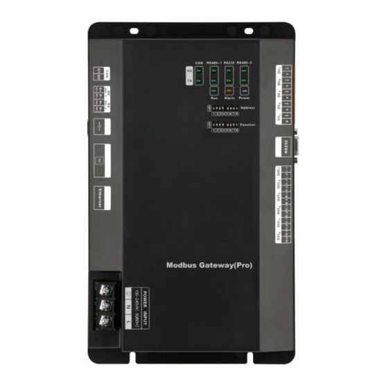
2.2 Gateway ME30-24/E5(M) 2.2.1 General Functions Gree Modbus Gateway(Pro) are intended to realize the data exchange between the air conditioner and BMS, and provides ten I/Os (five inputs are DI1, DI2, DI3, DI4, DI5 and five outputs are DO1, DO2, DO3, DO4, DO5). DI1 is the fire alarm interface (when there is fire alarm signal input, Modbus gateway will order all air conditioners to stop operation immediately). - Page 6 Modbus Gateway(Pro) Technical Service Manual 2.2.2 Appearance 2.2.3 Composition GMV gateway ME30-24/E5(M) contains the following parts: Modbus Gateway(Pro) 1 set User’s manual 1 piece Specification Gateway...
- Page 7 Modbus Gateway(Pro) Technical Service Manual 2.2.4 Interface 1)Diagram of interface communication interface RS485-1 communication interface DI Digital input RS485-2 communication interface RS232 USB interface communication SD card interface interface Ethernet interface DO digital output Power input 2)Power Supply Power supply should be 100VAC-240VAC, 50/60Hz. Warning! Protective grounding of power input must be connected, otherwise a hazard may happen;...
-
Page 8: Introduction Of Photoelectric Isolation Converter
Modbus Gateway(Pro) Technical Service Manual connection wire, to realize communication between Modbus Gateway(Pro) and air conditioner. RS485-1 communication interface:It is connected to BMS through two-core connection wire, to realize communication between Modbus Gateway(Pro) and BMS. RS485-2 communication interface: This device doesn’t use this communication interface currently. -
Page 9: Introduction Of Photoelectric Isolation Repeater
Modbus Gateway(Pro) Technical Service Manual Interface name Usage instructions Remark Converter Power interface Input 12VDC800mA equipped with power supply Wire A of RS485 connects with R+ of 485 For more details, Communication wiring terminal, wire B connects with R-. please refer to the interface RS232 interface connects with RS232 of user’s manual... - Page 10 Modbus Gateway(Pro) Technical Service Manual photoelectric isolation repeater must be used to transmit signals when node quantity in the network exceeds 30, so as to ensure the integrality of communication signal. Address value 1 2 3 4 5 6 7 8 1 1 0 1 Address DIP form...
- Page 11 Modbus Gateway(Pro) Technical Service Manual Interface name Usage instructions Remark Repeater Power interface Input 12VDC/800mA equipped with power supply For more details, Communication Wire A of RS485 connects with R+ of 485 please refer to the interface wiring terminal, wire B connects with R- user’s manual For more details, It is always bright when power supply is put...
-
Page 12: Device Installation
Modbus Gateway(Pro) Technical Service Manual 3.Device Installation 3.1 Product Dimension and Installation Space of Electric Control Cabinet 3.1.1 Product Dimension L × W × H:296×177×56(mm) 3.1.2 Installation Space of Electric Control Cabinet Modbus Gateway(Pro) shall be installed in the electric control cabinet. The front side of gateway shall be hung upwards and secured by four screws. -
Page 13: Communication Connection
Modbus Gateway(Pro) Technical Service Manual arrangement way of Modbus Gateway(Pro) and the placement status. ④ Each Modbus Gateway(Pro) shall have independent power supply. Therefore, sufficient 220V AC socket for power supply must be installed in the central control cabinet. ⑤ Keep the distance between communication cable and heavy current wire for more than 15cm and do not bind them together. - Page 14 Modbus Gateway(Pro) Technical Service Manual (2)Communicaiton connection between Modbus Gateway(Pro) and air conditioner (n is air conditioner quantity, n≤ 255); …… ODU system 1 ODU system 2 ODU system n Module 1 Module 1 Module 1 (master ODU) (master ODU) (master ODU) ODU system 3 Module 1...
- Page 15 Modbus Gateway(Pro) Technical Service Manual ① … ④ Slave Master ⑤ Modbus Gateway(Pro) 1 ② ⑤ … ④ Slave Master Modbus Gateway(Pro) 2 ③ 3.2.3 Communication Connection Steps (1)Communication wire connection between Modbus Gateway(Pro) and BMS: Step 1: Confirm the first Modbus Gateway(Pro) (Modbus Gateway(Pro)1 as shown in the figure) that needs to be connected to BMS.
- Page 16 Modbus Gateway(Pro) Technical Service Manual Step 2: Connect the G1 and G2 port of CAN communication interface of Modbus Gateway(Pro) and the G1 and G2 port of wiring board of corresponding master ODU with communication cable, as shown in step ⑤ in the figure. (3)DIP switch of Modbus Gateway(Pro): Step 1: Set address DIP switch of Modbus Gateway(Pro) by referring to chapter II.
-
Page 17: Chapter Ⅱ Debugging And Operation
Modbus Gateway(Pro) Technical Service Manual Chapter Ⅱ Debugging and Operation 1. Hardware Debugging 1.1 DIP Switches CAUTION! Please set DIP switches before using this device, otherwise this device cannot operate normally! This gateway includes two kinds of DIP switches, address DIP switch and function DIP switch. 1)Diagram of DIP Switches 2)Address DIP Switch –... - Page 18 Modbus Gateway(Pro) Technical Service Manual Setting method of address 43 is shown as below: Address value Address DIP form 3)The Seventh Switch of Function DIP Switch-Setting of Modbus Bus Matched Resistance CAUTION! Master outdoor unit or gateway of the system which is at the end of Modbus bus must be set as with the matched resistance, otherwise communication will be abnormal! Modbus bus: Detailed meaning please refer to topology introduction.
-
Page 19: Led Display
Modbus Gateway(Pro) Technical Service Manual Master Master Master control unit control unit control unit of ODU of ODU of ODU system n system 1 system 2 Master Master Master control unit control unit control unit of ODU of ODU of ODU system n system 1 system 2... -
Page 20: Di/Do
Modbus Gateway(Pro) Technical Service Manual RS485-2 This device does not use this LED indicator. When power supply of Modbus Gateway(Pro) is normal, it Power will be always on.. When Modbus Gateway(Pro) works normally, it will blink. Alarm This device doesn’t use this LED indicator. 1.3 DI/DO This gateway supports 5 DIs(digital inputs) and 5 DOs(digital outputs);... -
Page 21: Communication Debugging
Modbus Gateway(Pro) Technical Service Manual 2.Communication Debugging 2.1 Communication Debugging with Air Conditioning Equipment EQUIPMENT... -
Page 22: Communication Debugging With Bms System Equipment
Gateway(Pro) which complies with standard Modbus protocol regulation Malfunction 485-1 RX/TX light of Modbus Gateway(Pro) is blinking treatment 2 Communication between Modbus Gateway(Pro) and BMS system device is normal For BMS communication protocol, please make application from Gree Electric Appliances, Inc. of Zhuhai. -
Page 23: Malfunction Treatment
Modbus Gateway(Pro) Technical Service Manual 2.3 Malfunction Treatment Note: In malfunction treatment, several kinds of causes and troubleshooting methods are provided. If the malfunction cannot be solved, please contact relevant professionals from Gree. Malfunction treatment 1 CAN RX light of Modbus Gateway(Pro) is not bright Modbus Gateway(Pro) hasn’t received... - Page 24 Modbus Gateway(Pro) Technical Service Manual Malfunction treatment 2 485-1 RX/TX light of Modbus Gateway(Pro) is not blinking and without data replay Modbus Gateway(Pro) hasn’t received the data from BMS system equipment Check if the data Address of Modbus Communication cable gateway device hasn’t frame format sent by If communication...
-
Page 25: Chapter Ⅲ Maintenance
Modbus Gateway(Pro) Technical Service Manual Chapter Ⅲ Maintenance 1.Troubleshooting of BMS System Malfunction phenomenon Possible causes Troubleshooting Communication cable is not Change to twisted-pair twisted-pair communication communication cable cable Modbus Gateway(Pro) is broken Replace Modbus Gateway(Pro) There is breakage in the Weld the broken circuit communication cable BMS system displays communication error...
Need help?
Do you have a question about the ME30-24/E5 and is the answer not in the manual?
Questions and answers