Table of Contents
Advertisement
Advertisement
Table of Contents

Related Manuals for Gree ME30-24/E5


Summary of Contents for Gree ME30-24/E5
- Page 1 Owner's Manual Original Instructions Modbus Gateway(Pro) Models:ME30-24/E5(M)
- Page 2 (5) The final right to interpret for this instruction manual belongs to Gree Electric Appliances Inc. of Zhuhai.
- Page 3 User Notice Dear customer: Please read this manual carefully prior to installation and operation and strictly observe all installation and operation instructions covered in the manual. Special attentions shall be paid to the following marks: This mark indicates operation, which if improperly performed, WARNING! might lead to the death or serious injury of the users.
- Page 4 (4) After connection, lines should be protected with insulating tape to avoid oxidation and short circuits. (5) Normal working conditions for Modbus Gateway(Pro): ① Temperature : -20~+60℃; ② Humidity: less than 85% ③ Location: indoor (it is highly recommended to install this product in the electric control cabinet), not subject to direct sunlight, rain and snow etc.
-
Page 5: Table Of Contents
Contents 1 Safety Notices (Please be sure to abide ) ..........1 2 Function ......................1 2.1 General Functions ................1 3 Composition ....................2 4 Detailed Instruction of Modbus Gateway(Pro) ........3 4.1 Interfaces ..................3 4.2 LED display................... 6 4.3 DIP Switches ................ -
Page 6: Safety Notices (Please Be Sure To Abide )
DI3, DI4, DI5 and five outputs are DO1, DO2, DO3, DO4, DO5). DI1 is the fire alarm interface. The status of other I/Os is mapped to the specific objects of the Modbus bus and is defined by the user. This gateway is applicable for Gree multi VRF system which adopts CAN protocol. -
Page 7: Composition
Modbus Gateway(Pro) 3 Composition The product contains following items. Please check them prior to installation. Modbus Gateway(Pro) 1 set Owner’s Manual 1 set... -
Page 8: Detailed Instruction Of Modbus Gateway(Pro)
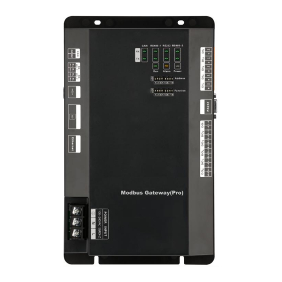
Modbus Gateway(Pro) 4 Detailed Instruction of Modbus Gateway(Pro) 4.1 Interfaces 4.1.1 Interface Function Drawing communication interface RS485-1 communication interface DI Digital input RS485-2 communication interface RS232 USB interface communication SD card interface interface Ethernet interface DO digital output Power input 4.1.2 Power The input power is 100VAC-240VAC and 50/60Hz. - Page 9 Modbus Gateway(Pro) Notice! Power cord should be secured with the equipped wire clip, as shown in the figure. 4.1.3 Communication interfaces CAN communication interface: It is connected to air conditioner through two-core connection wire, to realize communication between Modbus Gateway(Pro) and air conditioner.
- Page 10 Modbus Gateway(Pro) 4.1.4 DI/DO Digital Input/Output This gateway supports 5 DIs(digital inputs) and 5 DOs(digital outputs); DO6 is reserved. DI1...DI5 Digital inputs: 0/1 digital signals(binary system), applicable for those with power supply DI1: in CAN2 network, fire alarm signal, connect “1” to the power of 12V, input fire alarm signal “1”...
-
Page 11: Led Display
Modbus Gateway(Pro) 4.2 LED display LED indicators shown in the above figure are divided into two parts: status indicators (operation, alarm, power) and communication indicators(CAN, RS485, RS232). Operation status of each indicator is shown in the following table. When the data from the equipment (e.g. air conditioner) connected with Modbus Gateway(Pro) is received, it will flash. - Page 12 Modbus Gateway(Pro) 4.3.1 Diagram of DIP Switches This DIP is 0 This DIP is 1 High is the position of DIP 4.3.2 Address DIP Switch-Address Setting of Modbus Gateway(Pro) Address DIP switch is used for setting the device address of Modbus Gateway(Pro).
- Page 13 Modbus Gateway(Pro) Setting method of address 43 is shown as below: Address value Address DIP form 4.3.3 The Seventh Switch of Function DIP Switch-Setting of Modbus Bus Matched Resistance Notice! Master outdoor unit or gateway of the system which is at the end of Modbus bus must be set as with the matched resistance, otherwise communication will be abnormal! Modbus bus: Detailed meaning please refer to topology introduction.
- Page 14 Modbus Gateway(Pro) 4.3.4 The Eighth Switch of Function DIP Switch – Setting of CAN2 Bus Matched Resistance Notice! Master outdoor unit or gateway of the system which is at the end of CAN2 bus must be set as with the matched resistance, otherwise communication will be abnormal! ※CAN2 bus: Detailed meaning please refer to topology introduction.
-
Page 15: Application
This gateway adopts Modbus standard protocol, which can be used as the interface of BMS. It is applicable for Gree multi VRF which adopts CAN protocol when the VRF is connected to the BMS, to achieve monitoring of Gree multi VRF with BMS. -
Page 16: Internet Topological Graph
Modbus Gateway(Pro) 5.2 Internet topological graph 5.3 Topology Introduction: Modbus bus: L1 shown in the figure is the Modbus bus. CAN1 network: which is consist of Modbus Gateway(Pro) and all IDUs and ODUs of the system. One CAN1 network can be connected to maximum 80 IDUs. CAN2 network: which is consist of Modbus Gateway(Pro) and main control ODU of the system. -
Page 17: Installation
Modbus Gateway(Pro) s connected indoor units. Connectable unit quantity of Modbus Gateway(Pro): one Modbus Gateway(Pro) can be connected with 16 systems and 255 indoor units in maximum. 6 Installation 6.1 Product Dimension and Installation Space of Electric Control Cabinet 6.1.1 Product Dimension L ×... -
Page 18: Communication Connection
Modbus Gateway(Pro) 6.1.2 Installation Space of Electric Control Cabinet Modbus Gateway(Pro) shall be installed in the electric control cabinet. The front side of gateway shall be hung upwards and secured by four screws. Required installation space is shown as below (only for reference). 98.5mm Secure it by four... - Page 19 Modbus Gateway(Pro) 6.2.2 Communication Connection Way Notice! All communication cables of Modbus Gateway(Pro) must be connected in series instead of in star mode. (1) Communicaiton connection between Modbus and BMS; BMS system BMS system...
- Page 20 Modbus Gateway(Pro) (2) Communicaiton connection between Modbus Gateway(Pro) and air conditioner (n is air conditioner quantity, n≤ 255);...
- Page 21 Modbus Gateway(Pro) 6.2.3 Setting of Communication Connection ① „ ④ Slave Master ⑤ Modbus Gateway(Pro) 1 ② ⑤ „ ④ Slave Master Modbus Gateway(Pro) 2 ③ (1) Communication wire connection between Modbus Gateway(Pro) and BMS: Step 1: Confirm the first Modbus Gateway(Pro) (Modbus Gateway(Pro)1 as shown in the figure) that needs to be connected to BMS.
- Page 22 Modbus Gateway(Pro) (2) Communication wire connection between Modbus Gateway(Pro) and air conditioner: Step 1: Confirm the master ODU that each Modbus Gateway(Pro) shall be connected. Please refer to “6.2.2(2) Communicaiton connection between Modbus Gateway(Pro) and air conditioner” and adopt series connection, as shown in step ④...
- Page 23 Modbus Gateway(Pro) ② In “The eighth switch of function DIP switch – setting of CAN2 bus matched resistance”, the setting method of matched resistance of Modbus Gateway(Pro) is introduced. Meanwhile, the master ODU in the first and end systems of CAN2 bus shall be set as with matched resistance. In the following, the detailed setting position and method of matched resistance of GMV 5 DC inverter multi VRF are taken as example.
-
Page 24: Annex: Dip Address
Modbus Gateway(Pro) 7 Annex: DIP Address 0~31 DIP address table 32~63 DIP address table addr addr... - Page 25 Modbus Gateway(Pro) 64~95 DIP address table 96~127 DIP address table addr addr...
- Page 26 Modbus Gateway(Pro) 128~159 DIP address table 160~191 DIP address table addr addr...
- Page 27 Modbus Gateway(Pro) 192~223 DIP address table 224~255 DIP address table addr addr...
Need help?
Do you have a question about the ME30-24/E5 and is the answer not in the manual?
Questions and answers