Table of Contents
Advertisement
Advertisement
Table of Contents

Related Manuals for Gree ME30-24/E6


Summary of Contents for Gree ME30-24/E6
- Page 1 Modbus Gateway(Mini) model: ME30-24/E6(M)
- Page 2 To Users Thank you for selecting Gree’s product. Please read this instruction manual carefully before installing and using the product, so as to master and correctly use the product. In order to guide you to correctly install and use our product and...
- Page 3 (8) The final right to interpret for this instruction manual belongs to Gree Electric Appliances Inc. of Zhuhai.
-
Page 4: Table Of Contents
Contents 1 Safety Notices (Please be sure to abide) ..........1 2 User Notice..................1 3 General Functions ................3 4 Composition..................3 5 Detailed Introduction of Modbus Gateway(Mini) ......... 4 5.1 Interface ..................4 5.1.1 Interface Function Drawing ............4 5.1.2 Power .................. - Page 5 6.2 Topological Graph ................ 13 6.3 Topology Introduction..............13 7 Product installation ................15 7.1 Product Dimension and Installation Space of Electric Control Cabinet ................15 7.1.1 Product Dimension..............15 7.1.2 Installation Dimension of Electric Control Cabinet ......16 7.2 Communication Connection ............17 7.2.1 Material Selection of Communication Cable........
-
Page 6: Safety Notices (Please Be Sure To Abide)
Modbus Gateway(Mini) 1 Safety Notices (Please be sure to abide) Warning: If not abide strictly, it may cause severe damage to the unit or the people. Note: If not abide strictly, it may cause slight or medium damage to the unit or the people. This sign indicates that the operation must be prohibited. - Page 7 Modbus Gateway(Mini) (2)Do not place the plug of the power supply into the socket before it is dried and cleaned. (3)Cut off the power supply before touching the electric element. (4)Do not touch this device with wet hands; otherwise it would result in electric shock.
-
Page 8: General Functions
(6)Graphics in the instruction manual are for reference only. 3 General Functions Gree Modbus Gateway(Mini) is intended to realize the data exchange between the air conditioner and BMS, and provides standard Modbus RTU protocol. This gateway is applicable for DC Inverter GMV5, Water Source Heat Pump GMV5, GMV5 Mini, GMV5 Slim and GMV5 Heat Recovery. -
Page 9: Detailed Introduction Of Modbus Gateway(Mini)
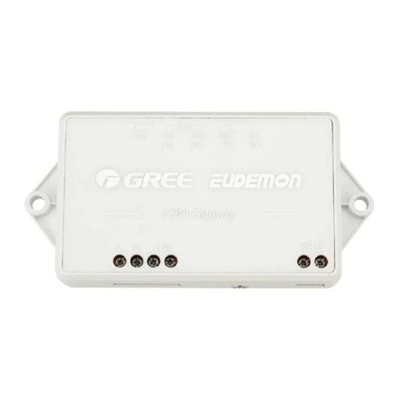
Modbus Gateway(Mini) Modbus Gateway(Mini) 1 set Owner’s Manual 1 set 5 Detailed Introduction of Modbus Gateway(Mini) Interface 5.1.1 Interface Function Drawing 5.1.2 Power The input power is 12V DC, external power supply can be prepared. -
Page 10: Communication Interfaces
Modbus Gateway(Mini) Note: pay attention to the polarity of power input and connect power according to the interface instruction. 5.1.3 Communication Interfaces CAN communication interface: It is connected to air conditioner through two- core connection wire, to realize communication between Modbus Gateway(Mini) and air conditioner. -
Page 11: Led Display
Modbus Gateway(Mini) RS485 communication interface: It is connected to BMS through two-core communication cable, to realize communication between Modbus Gateway(Mini) and BMS or nearby Modbus Gateway(Mini). LED Display LED indicators shown in the above figure are divided into two parts: status indicators (power) and communication indicators(CAN, RS485). -
Page 12: Dip Switches
Modbus Gateway(Mini) DIP Switches Notice! Please set DIP switches before using this gateway. Re-energize the device after setting DIP switches. Otherwise this device cannot operate normally! Setting area of Modbus gateway DIP switch is located inside the product, including address DIP switch and function DIP switch. 5.3.1 Setting of Address DIP Switch (1) Address DIP switch consists of S1 and S2. -
Page 13: Address Dip Switch S1,S2-Address Setting Of Modbus
Modbus Gateway(Mini) 5.3.2 Address DIP Switch S1,S2—Address Setting of Modbus Gateway Notice! Please set the address DIP switches before using this gateway. The network DIP switch address of the same bus cannot be repeated, otherwise communication error may happen. Modbus Gateway(Mini) address setting range: 1~255. Detailed DIP value please refer to the Address DIP Form. -
Page 14: The Fourth Switch Of Function Dip Switch S3 - Setting Of Can2 Bus
Modbus Gateway(Mini) Setting method of address 43 is shown as below: 5.3.3 The Fourth Switch of Function DIP Switch S3 - Setting of CAN2 Bus Matched Resistance Notice! Notice! Master outdoor unit or gateway of the system which is at the end of CAN2 bus must be set as with the matched resistance, otherwise communication will be abnormal! The fourth switch of function DIP switch is used for setting the CAN2 bus... -
Page 15: The Third Switch Of Function Dip Switch S3 - Setting Of Modbus Bus
Modbus Gateway(Mini) If the Modbus gateway is at the end of CAN2 bus, the gateway shall be set as with the matched resistance, which means set the fourth DIP switch to 0; If the Modbus gateway is not at the end of CAN2 bus, the gateway shall be set as without the matched resistance, which means set this DIP switch to 1. -
Page 16: The Second Switch Of Function Dip Switch S3 - Setting Of Gateway Starting Idu Project Number
Modbus Gateway(Mini) If the Modbus gateway is at the end of Modbus bus, the gateway shall be set as with the matched resistance, which means set the third DIP switch to 0; If the Modbus gateway is not at the end of Modbus bus, the gateway shall be set as without the matched resistance, which means set this DIP switch to 1. -
Page 17: Application
Modbus Gateway(Mini) 6 Application Modbus Gateway(Mini) is usually applicable for Building Management System. Building Management System (BMS) This gateway adopts Modbus standard protocol, which can be used as the interface of BMS. It is applicable for DC Inverter GMV5, Water Source Heat Pump GMV5, GMV5 Mini, GMV5 Slim and GMV5 Heat Recovery. -
Page 18: Topological Graph
Modbus Gateway(Mini) Topological Graph Topology Introduction Modbus bus: L1 shown in the figure is the Modbus bus. - Page 19 Modbus Gateway(Mini) CAN1 network: network ③ shown in the figure is the CAN1 network, which is consist of Modbus Gateway(Mini) and all IDUs and ODUs of the system. One CAN1 network can be connected to maximum 80 IDUs. L3 shown in the network is CAN1 bus.
-
Page 20: Product Installation
Modbus Gateway(Mini) 7 Product installation Product Dimension and Installation Space of Electric Control Cabinet 7.1.1 Product Dimension... -
Page 21: Installation Dimension Of Electric Control Cabinet
Modbus Gateway(Mini) 7.1.2 Installation Dimension of Electric Control Cabinet Modbus Gateway(Mini) shall be installed in the electric control cabinet. The front side of gateway shall be hung upwards in horizontal level and secured by two screws. Required installation space is shown as below (only for reference). -
Page 22: Communication Connection
Modbus Gateway(Mini) Communication Connection Communication system of Modbus Gateway(Mini) includes: (1)Communication between Modbus Gateway(Mini) and BMS; (2)Communication between Modbus Gateway(Mini) and air conditioner. -
Page 23: Material Selection Of Communication Cable
Modbus Gateway(Mini) 7.2.1 Material Selection of Communication Cable Comm- Cable Communicati- unicati- Material of Material diameter Remark on system on cable cable standard L(m) When communic- Light/ ation Communicati- Ordinary distance on between exceeds Modbus sheathed L≤800 ≥2×0.75 C60227- 800m, Gateway(- twisted pair 5:2007... - Page 24 Modbus Gateway(Mini) (1)Communicaiton connection between Modbus Gateway(Mini) and BMS;...
- Page 25 Modbus Gateway(Mini) (2) Communication connection between Modbus Gateway(Mini) and air conditioner (n is air conditioner quantity, n≤16);...
- Page 26 Modbus Gateway(Mini)
-
Page 27: Setting Of Communication Connection
Modbus Gateway(Mini) 7.2.3 Setting of Communication Connection (1) Communication wire connection between Modbus Gateway(Mini) and BMS: Step 1: Confirm the first Modbus Gateway(Mini) (Modbus Gateway(Mini)1 as shown in the figure) that needs to be connected to BMS. Connect the port of RS485 of this gateway and the BMS with communication cable, as shown in step ①... - Page 28 Modbus Gateway(Mini) Step 2: Connect the RS485 communication port of Modbus Gateway(Mini) (- Modbus Gateway(Mini)1) with the RS485 communication port of the second Modbus Gateway(Mini) (Modbus Gateway(Mini)2 as shown in the figure) with communication cable; as shown in step ② in the figure. Step 3: The other Modbus Gateway(Mini)shall be connected in series;...
- Page 29 Modbus Gateway(Mini) 2. In “5.3.3 The fourth switch of DIP switch S3——setting of CAN2 bus matched resistance”, the setting method of matched resistance of Modbus Gateway(Mini) is introduced. Meanwhile, the master ODU in the first and end systems of CAN2 bus shall be set as with matched resistance.
-
Page 30: Annex: Dip Address
Modbus Gateway(Mini) ※ CAN2 bus: Detailed meaning please refer to topology introduction. 8 Annex: DIP Address 0~31 DIP address table 32~63 DIP address table... - Page 31 Modbus Gateway(Mini) 0 10 0 11 0 12 0 13 0 14 0 15 0 16 0 17 0 18 0 19 0 20 0 21 0 22...
- Page 32 Modbus Gateway(Mini) 0 23 0 24 0 25 0 26 0 27 0 28 0 29 0 30 0 31 64~95 DIP address table 96~127 DIP address table 0 64 0 65 0 66 0 67 0 68 0 100 0 69 0 101 0 70...
- Page 33 Modbus Gateway(Mini) 0 71 0 103 0 72 0 104 0 73 0 105 0 74 0 106 0 75 0 107 0 76 0 108 0 77 0 109 0 78 0 110 0 79 0 111 0 80 0 112 0 81 0 113...
- Page 34 Modbus Gateway(Mini) 0 91 0 123 0 92 0 124 0 93 0 125 0 94 0 126 0 95 0 127 128~159 DIP address table 160~191 DIP address table 1 128 1 160 1 129 1 161 1 130 1 162 1 131 1 163...
- Page 35 Modbus Gateway(Mini) 1 140 1 172 1 141 1 173 1 142 1 174 1 143 1 175 1 144 1 176 1 145 1 177 1 146 1 178 1 147 1 179 1 148 1 180 1 149 1 181 1 150 1 182...
- Page 36 Modbus Gateway(Mini) 192~223 DIP address table 224~255 DIP address table 1 192 1 224 1 193 1 225 1 194 1 226 1 195 1 227 1 196 1 228 1 197 1 229 1 198 1 230 1 199 1 231 1 200 1 232...
- Page 37 Modbus Gateway(Mini) 1 209 1 241 1 210 1 242 1 211 1 243 1 212 1 244 1 213 1 245 1 214 1 246 1 215 1 247 1 216 1 248 1 217 1 249 1 218 1 250 1 219 1 251...
Need help?
Do you have a question about the ME30-24/E6 and is the answer not in the manual?
Questions and answers