Advertisement
Quick Links
Please visit our website for the most current instructions, assembly tips, to report damage
or request parts. www.walkeredison.com
Copyright © 2018, by Walker Edison Furniture Co., LLC, All rights reserved.
Copyright © 2018, by Walker Edison Furniture Co., LLC, All rights reserved.
Item: CMAB5C
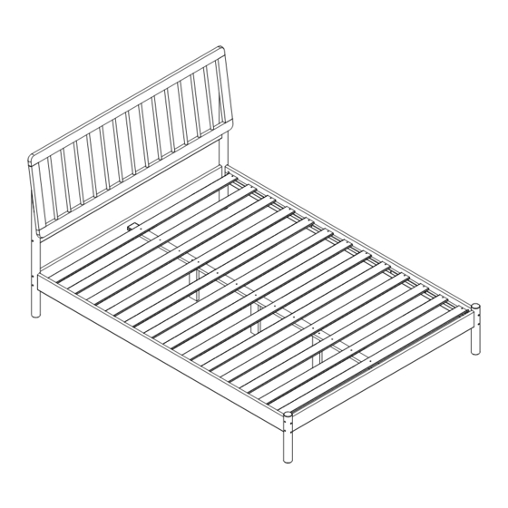
Assembly Instructions
Revised
04/23
-V0
P.1
Advertisement

Related Manuals for Walker Edison CMAB5C


Summary of Contents for Walker Edison CMAB5C
- Page 1 Please visit our website for the most current instructions, assembly tips, to report damage or request parts. www.walkeredison.com Revised 04/23 Copyright © 2018, by Walker Edison Furniture Co., LLC, All rights reserved. Copyright © 2018, by Walker Edison Furniture Co., LLC, All rights reserved.
-
Page 3: Parts List
Parts List 02 pcs 03 pcs Center Foot Headboard And Footboard Platter 01 pcs Center Slat 01 pcs Headboard Middle Crosspiece 01 pcs Headboard Left Foot Headboard Right Foot 01 pcs 01 pcs Left Foot Of The Footboard Right Foot Of The Footboard 01 pcs 02 pcs Crosspiece... -
Page 4: Hardware List
Hardware List 12 pcs Bolt ø7,0"*40mm 14 pcs Bolt ø7,0"*80mm 04 pcs Bolt ø1/4"*90mm Hex key 01 pc 04 pcs 39 pcs ø4.0*30mm Screw 02 pcs Space Block 08 pcs ø4.0*16mm Screw Support 02 pcs 10 pcs ø10*40mm Dowel Philips head screwdriver required for assembly (not included) The hardware quantities listed above are required for proper assembly. - Page 5 Step 1 Insert the dowel K to the parts 1, 3, 4 and 7. ø10*40mm Step 2 ø7,0"*80mm Attach part 1 and 2 to part 3 and 4 with screw B and hex key D.
- Page 6 Step 3 Name and address of the supplier and date of production. ø7,0"*80mm Attach part 1 to part 5 and 6 with screw B and hex key D. Step 4 ø4.0*16mm Apply support J on part 1 and fix with screw I and phillips head screwdriver.
- Page 7 Step 5 ø7,0"*80mm ø1/4"*90mm Attach part 7 with feet 4, fix with screw B, C and nut E with hex key D Step 6 ø7,0"*80mm ø1/4"*90mm Attach part 7 with feet 6, fix with screw B, C and nut E with hex key D...
- Page 8 Step 7 ø7,0"*80mm ø1/4"*90mm Attach part 7 with feet 3 and 5, fix with screw B, C and nut E with hex key D Step 8 ø7,0"*40mm Attach parts 8 on feet 3 and 4 with screw A and hex key D...
- Page 9 Step 9 ø7,0"*40mm Attach parts 10 to part 11 with screw A and hex key D Step 10 Attach part 11 to support with screw I ø4.0*16mm and phillips head screwdriver.
- Page 10 Step 11 Align part 7 with 9, attach part 9 to part 7 and 11 with screw F and phillips head screwdriver. ø4.0*30mm Use hardware G to space the next parts 9 and attach to parts 7 and 11 with screw F and phillips head screwdriver. Step 12 P.10...
Need help?
Do you have a question about the CMAB5C and is the answer not in the manual?
Questions and answers