Burkert ME44 Quick Start Manual
Hide thumbs
Also See for ME44:
- Operating instructions manual (86 pages) ,
- Quick start manual (15 pages) ,
- Operating instructions manual (110 pages)
Chapters
Table of Contents

Related Manuals for Burkert ME44

Summary of Contents for Burkert ME44
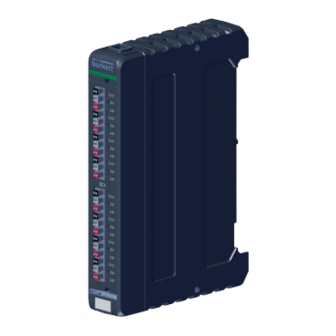
- Page 1 Type ME44 / BPX3 I/O-Module / Backplane 8DI module, 8DO module, 4AI module, 4AO module 8DI-Modul, 8DO-Modul, 4AI-Modul, 4AO-Modul Module 8DI, module 8DO, module 4AI, module 4AO Quickstart...
-
Page 2: Table Of Contents
▶ Persons, who work on the device, must read and understand these instructions. Installation ..................6 The operating instructions can be found on the Internet at: Start-up ..................11 www.burkert.com Display elements ................11 Symbols Maintenance ................... 12 ▶ Highlights instructions to avoid a danger. -
Page 3: Intended Use
▶ The I/O module Type ME44 collects, converts and compares physical The operator is responsible for observing the location-specific safety measurement data from external sensors or receives switching com- regulations, also with reference to the personnel. -
Page 4: Technical Data
TECHNICAL DATA NOTE! The following values are indicated on the device: Electrostatically sensitive components and modules. • Supply voltage The device contains electronic components that are susceptible to • Permitted ambient temperature range electrostatic discharging (ESD). Components that come into contact with electrostatically charged people or objects are at risk. - Page 5 4.3 Mechanical data Order number Type Housing material: Polycarbonate Manufacturer 4.4 Device labeling Serial number code (coded) UL marking* Order number UL marking* Type Ambient temperature Manufacturer code (coded) Module Serial number variant Supply voltage Nominal power Degree of protection CE marking CE marking * only UL version...
-
Page 6: Installation
4.5 Electrical data INSTALLATION Supply voltage: 24 V ±10 % via the backplane BPX3 NOTE! Power consumption: 4AI: 3.5 W 8DI: 10 W Installation may be carried out only by trained technicians and with the appropriate tools! 4AO: 3.5 W 8DO: Mounting the fieldbus gateway on the Current consumption: 4AI:... - Page 7 Module slots Module slots with covers The ME44 I/O module and the BPX3 backplane can only be operated as part of a system in combination with the ME43 Fig. 4: Mounting the I/O module Type ME44 on the backplane fieldbus gateway.
- Page 8 Electrical configuration 8DO module: Use supply voltage unit with adequate power. Plug configuration External circuit AUX Power 5.3 Electrical installation Ground The circuit diagram is pressed onto the outside of the I/O module. Ground NOTE! Aux power supply voltage 24 V Precondition to ensure that the device functions perfectly and to 24 V ±10 %...
- Page 9 Electrical configuration 4AI module: Electrical configuration 4AO module: Plug configuration Plug configuration External circuit External circuit AUX Power analogue outputs Ground Ground Ground AO1...AO4 Analogue output + Tab. 4: Electrical configuration 4AO module Aux power supply voltage 24 V 24 V ±10 % 5.3.1 Connecting external sensors and actuators Aux power supply voltage...
- Page 10 5.3.2 Connection of the cable shielding 5.4 Mounting the system on the standard rail → Hook the system into the lower guide of the NOTE! standard rail. Precondition to ensure that the device functions perfectly. → Push the system upward while tilting it to the The cable shielding must be placed on both ends of the line to the left and lock it into the upper guide of the functional earth:...
-
Page 11: Start-Up
START-UP DISPLAY ELEMENTS The I/O modules of Type ME44 have the following LEDs for indicating Configuration the status. The Bürkert Communicator software is required to configure the • LED for indicating the device status. I/O module Type ME44. The LED changes color and status in accordance with NAMUR NE 107. -
Page 12: Maintenance
MAINTENANCE Replacement of the I/O module NOTE! Maintenance may be carried out only by trained technicians and with the appropriate tools! I/O modules can be replaced during operation (hot plug). Remove cables from sensors and actuators. → Press push-in contacts of the terminal block and pull out wires. Fig. -
Page 13: Disassembly
DISASSEMBLY Install replacement device. → Align the I/O module with the module slot of the backplane. CAUTION! → Press the I/O module onto the backplane until it clicks to position. Electrical voltage. → Connect wires of the external sensors and actuators to the terminals ▶... -
Page 14: Transportation, Storage, Disposal
▶ Store the device in a dry and dust-free location. ▶ Storage temperature: –30 °C to +80 °C. Environmentally friendly disposal ▶ Follow national regulations regarding disposal and the environment. ▶ Collect electrical and electronic devices separately and dispose of them as special waste. Further information at country.burkert.com english... -
Page 15: Der Quickstart
DER QUICKSTART Inhaltsverzeichnis Der Quickstart enthält die wichtigsten Informationen zum Gerät. Diese Der Quickstart ................. 15 Anleitung am Einsatzort griffbereit aufbewahren. Bestimmungsgemäße Verwendung ..........16 Wichtige Informationen zur Sicherheit. ▶ Diese Anleitung sorgfältig lesen. Vor allem Sicherheitshinweise, Grundlegende Sicherheitshinweise..........16 bestimmungsgemäße Verwendung und Einsatzbedingungen Technische Daten ................ -
Page 16: Bestimmungsgemäße Verwendung
Montage, Betrieb und Wartung auftreten können. für Personen, Anlagen in der Umgebung und die Umwelt entstehen. ▶ I/O-Modul Typ ME44 sammelt, wandelt und vergleicht physikalische Der Betreiber ist dafür verantwortlich, dass die ortsbezogenen Sicher- Messdaten externer Sensoren oder erhält über die büS-Schnittstelle heitsbestimmungen, auch in Bezug auf das Personal, eingehalten werden. -
Page 17: Technische Daten
TECHNISCHE DATEN ACHTUNG! Folgende Werte sind auf dem Gerät angegeben: Elektrostatisch gefährdete Bauelemente und Baugruppen. • Versorgungsspannung Das Gerät enthält elektronische Bauelemente, die gegen elektrostatische • Zulässiger Umgebungstemperaturbereich Entladung (ESD) empfindlich reagieren. Berührung mit elektrostatisch aufgeladenen Personen oder Gegenständen gefährdet diese Bauele- Normen und Richtlinien mente. - Page 18 4.3 Mechanische Daten Bestellnummer Gehäusematerial: Polycarbonat Herstellcode 4.4 Gerätebeschriftung Seriennummer Umgebungs- UL-Kennzeichen* Bestellnummer UL-Kennzeichen temperatur Herstellcode Modul- Seriennummer variante Versorgungsspannung Nennleistung Schutzart CE-Kennzeichen CE-Kennzeichen * nur bei UL-Version vorhanden Bild 2: Beschreibung Gerätebeschriftung (Backplane) Umgebungstemperatur QR-Code (weitere Informationen zum Gerät) * nur bei UL-Version vorhanden Bild 1: Beschreibung Gerätebeschriftung (Modul) deutsch...
-
Page 19: Installation
4.5 Elektrische Daten INSTALLATION Versorgungsspannung: 24 V ±10 % über die Backplane BPX3 ACHTUNG! Leistungsaufnahme: 4AI: 3,5 W 8DI: 10 W Die Installation darf nur geschultes Fachpersonal mit geeignetem Werkzeug durchführen. 4AO: 3,5 W 8DO: Feldbus-Gateway an Backplane montieren Stromaufnahme: 4AI: 4 x 50 mA 8DI: 8 x 30 mA... - Page 20 Abdeckungen mit der Abdeckung verschließen. Bild 4: I/O-Modul Typ ME44 auf Backplane montieren Das I/O-Modul ME44 und die Backplane BPX3 können nur als → I/O-Modul zum Modulsteckplatz der Backplane ausrichten. Teil eines Systems in Kombination mit dem Feldbus-Gateway → I/O-Modul auf die Backplane drücken, bis es einrastet.
- Page 21 Elektrische Belegung 8DO-Modul: Versorgungsspannung mit ausreichender Leistung verwenden. Steckerbelegung Äußere Beschaltung AUX Power 5.3 Elektrische Installation Masse Der Schaltplan ist auf der Außenseite des I/O-Moduls aufgedruckt. Masse ACHTUNG! Aux Power Versorgungs- Voraussetzung für die einwandfreie Funktion des Geräts und zur Ver- 24 V spannung meidung von Störeinflüssen:...
- Page 22 Elektrische Belegung 4AI-Modul: Elektrische Belegung 4AO-Modul: Steckerbelegung Steckerbelegung Äußere Beschaltung Äußere Beschaltung AUX Power analoge Ausgänge Masse Masse Masse AO1...AO4 Analoger Ausgang + Tab. 4: Elektrische Belegung 4AO-Modul Aux Power Versorgungs- 24 V spannung 5.3.1 Externe Sensoren und Aktoren elektrisch 24 V ±10 % anschließen...
- Page 23 5.3.2 Kabelschirmung anschließen 5.4 System auf Normschiene montieren → System in die untere Führung der Normschiene ACHTUNG! einhängen. Voraussetzung für die einwandfreie Funktion des Geräts. → System nach oben drücken, dabei zur Norm- Die Kabelschirmung muss an beiden Leitungsenden auf die Funkti- schine schwenken und in obere Führung der onserde aufgelegt werden: Normschiene einrasten.
-
Page 24: Inbetriebnahme
INBETRIEBNAHME ANZEIGEELEMENTE Die I/O-Module des Typs ME44 besitzen zur Anzeige der Status folgende Konfiguration LEDs. Für die Konfiguration des I/O-Moduls Typ ME44 wird die Software • LED zur Anzeige des Gerätestatus. Bürkert Communicator benötigt. Die LED wechselt Farbe und Status in Anlehnung an NAMUR NE 107. -
Page 25: Wartung
WARTUNG I/O-Modul tauschen ACHTUNG! Die Wartung darf nur geschultes Fachpersonal mit geeignetem Werkzeug durchführen! I/O-Module können während des laufenden Betriebs getauscht werden (Hot plug). Kabel für Sensoren und Aktoren entfernen. → Push-in-Kontakte der Anschlussklemme drücken und Adern herausziehen. Bild 6: I/O-Modul abnehmen I/O-Modul von der Backplane entfernen. -
Page 26: Demontage
DEMONTAGE Tauschgerät montieren. → I/O-Modul zum Modulsteckplatz der Backplane ausrichten. VORSICHT! → I/O-Modul auf die Backplane drücken, bis es einrastet. Elektrische Spannung. → Externe Sensoren und Aktoren elektrisch anschließen. ▶ Vor Arbeiten an Gerät oder Anlage die Spannung abschalten. Gegen Wiedereinschalten sichern. Feldbus- Backplane Montiertes System... -
Page 27: Transport, Lagerung, Entsorgung
Falsche Lagerung kann Schäden am Gerät verursachen. ▶ Gerät trocken und staubfrei lagern. ▶ Lagertemperatur: –30 °C…+80 °C. Umweltgerechte Entsorgung ▶ Nationale Vorschriften bezüglich Entsorgung und Umwelt beachten. ▶ Elektrische und elektronische Geräte separat sammeln und speziell entsorgen. Weitere Informationen unter country.burkert.com deutsch... -
Page 28: Quickstart
Installation ..................32 comprendre le présent manuel d'utilisation. Mise en service ................37 Le manuel d’utilisation est disponible sur Internet, sous : Éléments d'affichage ............... 37 www.burkert.fr Maintenance ................... 38 Symboles Démontage ..................39 Identifie une instruction que vous devez respecter pour éviter ▶... -
Page 29: Utilisation Conforme
Ces consignes de sécurité ne tiennent pas compte des hasards et des ▶ Le module E/S type ME44 collecte, convertit et compare des données événements pouvant survenir lors du montage, de l’exploitation et de la de mesure physiques de capteurs externes ou reçoit par l’intermédiaire... -
Page 30: Caractéristiques Techniques
CARACTÉRISTIQUES TECHNIQUES REMARQUE ! Les valeurs suivantes sont indiquées sur la plaque signalétique : Éléments et sous-groupes sujets aux risques électrostatiques. • Tension d'alimentation L'appareil contient des éléments électroniques sensibles aux décharges • Plage de température ambiante admissible électrostatiques (ESD). Ces éléments sont affectés par le contact avec des personnes ou des objets ayant une charge électrostatique. - Page 31 4.3 Caractéristiques mécaniques Numéro de commande Type Matériau du corps : polycarbonate Code de fabri- cation (codé) 4.4 Inscription sur l’appareil Numéro de série Température Marquage UL* Numéro de commande ambiante Type Marquage UL* Variante Code de fabrication (codé) Numéro de série module Tension d’alimentation Puissance nominal...
-
Page 32: Installation
4.5 Caractéristiques électriques INSTALLATION Tension d'alimentation : 24 V ±10 % au-dessus du backplane REMARQUE ! BPX3 L'installation doit être effectuée uniquement par un personnel qualifié et habilité disposant de l'outillage approprié. Puissance absorbée : 4AI: 3,5 W 8DI: 10 W 4AO: 3,5 W 8DO: Monter la passerelle de bus de terrain sur le backplane... - Page 33 Le module d‘E/S ME44 et le backplane BPX3 ne peuvent être Fig. 4 : Monter le module E/S type ME44 sur le backplane exploités que dans le cadre d‘un système en combinaison avec →...
- Page 34 Affectation électrique du module 8DO : Utiliser une tension d'alimentation présentant suffisamment de puissance. Affectation des connecteurs Câblage externe 5.3 Installation électrique AUX Power Le schéma de connexions est imprimé sur la face extérieure du Terre module E/S. Terre REMARQUE ! Condition préalable à...
- Page 35 Affectation électrique du module 4AI : Affectation électrique du module 4AO : Affectation des Affectation des connecteurs Câblage externe connecteurs Câblage externe AUX Power Sortie analogue Terre Terre Terre AO1...AO4 Sortie analogue + Tension d’alimentation Aux 24 V Tab. 4 : Affectation électrique du module 4AO Power 24 V ±10 %...
- Page 36 5.3.2 Raccordement du blindage de câble 5.4 Monter l’appareil sur rail normalisé → Accrocher l‘appareil au guidage inférieur du rail REMARQUE ! normalisé. Condition préalable pour le fonctionnement correct de l’appareil. → Pousser l‘appareil vers le haut tout en le faisant Le blindage de câble doit être adapté...
-
Page 37: Mise En Service
MISE EN SERVICE ÉLÉMENTS D'AFFICHAGE Les modules E/S de type ME44 disposent des LED suivantes pour Configuration l’affichage d’état. Le logiciel Bürkert Communicator est nécessaire pour configurer • LED pour l'affichage de l'état de l'appareil. le module E/S type ME44. -
Page 38: Maintenance
MAINTENANCE Remplacement du module E/S REMARQUE ! La maintenance doit uniquement être effectuée par un personnel qua- lifié et habilité disposant de l’outillage approprié ! Les modules E/S peuvent être remplacés en cours de fonction- nement (hot plug). Retirer les câbles des capteurs et actionneurs. →... -
Page 39: Démontage
DÉMONTAGE Monter l’appareil de rechange. → Aligner le module E/S par rapport à la fiche de connexion du module ATTENTION ! du backplane. Tension électrique. → Pousser le module E/S sur le backplane jusqu’à ce qu’il s’encrante. ▶ Couper la tension avant d'intervenir dans l'installation ou l'appareil. →... -
Page 40: Transport, Stockage, Élimination
▶ Température de stockage : –30 °C á +80 °C. Élimination écologique ▶ Respecter les réglementations nationales en matière d’élimination et d’environnement. ▶ Collecter séparément les appareils électriques et électro- niques et les éliminer de manière spécifique. Pour plus d’informations, consulter le site country.burkert.com français... - Page 41 Fax + 49 (0) 7940 - 10-91 448 E-mail: info@burkert.com International address www.burkert.com Manuals and data sheets on the Internet : www.burkert.com Bedienungsanleitungen und Datenblätter im Internet: www.buerkert.de Manuels d'utilisation et fiches techniques sur Internet: www.burkert.fr © Bürkert Werke GmbH & Co. KG, 2018 - 2023 Operating Instructions 2304/04_EUml_00815356 / Original DE www.burkert.com...
Need help?
Do you have a question about the ME44 and is the answer not in the manual?
Questions and answers