
Related Manuals for VAMP 221


Summary of Contents for VAMP 221
- Page 1 VAMP 221 Arc protection system Operation and configuration instructions Technical description...
- Page 2 VAMP 221 Arc protection system VAMP Ltd Operation and configuration instructions VAMP 24h Technical Support: +358 (0)20 753 3264 VM221.EN013...
-
Page 3: Table Of Contents
DP .................8 1.1.4. Other system components........12 1.2. Operational safety............13 2. User interface ...............14 2.1. Front panel of the central unit VAMP 221 .....14 2.1.1. Display and status indications .......15 2.1.2. Buttons and programming switches.....16 2.1.3. Moving in menus............17 2.2. I/O unit front panels ............18 2.2.1. -
Page 4: General
1.1. VAMP 221 arc protection system components VAMP 221 is an easily adaptable arc protection system for the protection of electricity distribution systems. VAMP 221 significantly reduces the risk of potential personal damage, and material and production losses caused by arc fault. - Page 5 Operation and configuration instructions Figure 1.1-1 VAMP 221 Arc Protection System VAMP 221 is a modular system consisting of a central unit, I/O units, arc sensors and possible multiplying relays. Thanks to its modularity, the system can easily be adapted to...
-
Page 6: Central Unit Vamp 221
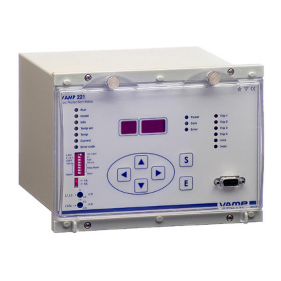
VAMP Ltd Operation and configuration instructions 1.1.1. Central unit VAMP 221 Figure 1.1.1-1 The central unit VAMP 221 The central unit VAMP 221 contains the following functions: 3-phase overcurrent and arc stage • Alternatively, 2-phase overcurrent, earth-fault and arc •... - Page 7 VAM 4C). Connection for a portable arc sensor (VAM 10L , 3LX and • Free placement in the switchgear. • Intra-unit cabling with factory-made modular cable or • instrumentation cable. VM221.EN013 VAMP 24h support phone : +358 (0)20 753 3264...
-
Page 8: Arc Sensors Va 1 Da, Va 1 Eh, Arc-Slx And Va
The sensor type offers a cost-effective arc protection • solution Easy to install and repair (after arc faults, for example) • Normal installation involves one sensor in each switchgear • compartment Self-supervised arc sensor • VAMP 24h Technical Support: +358 (0)20 753 3264 VM221.EN013... - Page 9 The sensor type offers a cost-effective arc protection • solution The sensor can be installed in a tube, for example, so that • the active light detector sees the monitored zone. Self-supervised arc sensor • VM221.EN013 VAMP 24h support phone : +358 (0)20 753 3264...
- Page 10 The fibre will be installed to go through the supervised • compartments Monitoring the light information with a fibre system is a • cost-effective solution e.g. in low voltage switchgears with several compartments Self-supervised arc sensor • VAMP 24h Technical Support: +358 (0)20 753 3264 VM221.EN013...
- Page 11 (VAM 10L, VAM 3L or VAM 3LX) using a snap-in connector Cable length 5 metres • The sensor is designed to be attached e.g. to the edge of a • pocket in the technician’s working wear VM221.EN013 VAMP 24h support phone : +358 (0)20 753 3264...
-
Page 12: Other System Components
Figure 1.1.4-1 Multiplying relay VAR 4CE Four potential-free electromechanical output trip relays. • Multiplying relay operating time 5 ms • Control either through the I/O unit trip relay or DO output • VAMP 24h Technical Support: +358 (0)20 753 3264 VM221.EN013... -
Page 13: Operational Safety
Disconnecting the secondary circuit of a live current transformer may cause dangerous overcurrents! Always observe all national and regional regulations and guidelines. Read any instructions carefully before performing any operations. VM221.EN013 VAMP 24h support phone : +358 (0)20 753 3264... -
Page 14: User Interface
VAMP Ltd Operation and configuration instructions User interface The control and acknowledgement functions of the VAMP 221 arc protection system are mainly carried out using the push buttons on the central unit. Information on equipment status and operation can also be read on the central unit’s display and indicator lights. -
Page 15: Display And Status Indications
Trip 3 Error Current Trip 4 Error code I>int. I>ext. VMAP221_disp Figure 2.1.1-1 Central unit VAMP 221 - display and status indications 1. Operating status indication lights, see section ‘Moving in menus’ normal operation INSTALL system configuration INFO system configuration check... -
Page 16: Buttons And Programming Switches
7. ENTER push button for executing functions 8. Communication port for loading software updates, not needed in normal operation. For more details on the trip relay matrix, see section 3.3 Using programming switches. VAMP 24h Technical Support: +358 (0)20 753 3264 VM221.EN013... -
Page 17: Moving In Menus
ERROR CODE ERROR CODE Use push-button for Sensor no. or clearing error codes (one error code error code in time) MMI-Guide Figure 2.1.3-1 Moving in the mode menu VM221.EN013 VAMP 24h support phone : +358 (0)20 753 3264... -
Page 18: I/O Unit Front Panels
(zone/address, trip output) in the I/O unit. NOTE! If you unfasten the terminal blocks during installation, remember to tighten the fixing screws after installation! Also tighten the screws even if you did not unfasten the blocks. VAMP 24h Technical Support: +358 (0)20 753 3264 VM221.EN013... -
Page 19: Vam 10L - Front Panel
9. Portable arc sensor VA 1 DP connected and operational 10. Portable arc sensor activated 11. I/O unit trip relay activated 12. Terminal block for external communication and BI/O channels and trip signal VM221.EN013 VAMP 24h support phone : +358 (0)20 753 3264... -
Page 20: I/O Unit Vam 3L - Front Plate
9. Portable arc sensor VA 1 DP connected and operational 10. Portable arc sensor activated 11. I/O unit trip relay activated 12. Terminal block for external communication and BI/O channels and trip signal VAMP 24h Technical Support: +358 (0)20 753 3264 VM221.EN013... -
Page 21: I/O Unit Vam 3Lx - Front Plate
10. Portable arc sensor activated 11. I/O unit trip relay activated 12. Terminal block for external communication and BI/O channels and trip signal 13. Sensitivity adjustments for each fibre sensor channels VM221.EN013 VAMP 24h support phone : +358 (0)20 753 3264... -
Page 22: I/O Unit Vam 4C - Front Plate
6. LED lights indicating that I> stage has started 7. Terminals for three current transformers 8. Current transformer programming switches 9. Overcurrent setting knob (I ), setting range 0.5…6xI 10. Overcurrent setting knob (I ), setting range 0.05…5xI VAMP 24h Technical Support: +358 (0)20 753 3264 VM221.EN013... -
Page 23: Multiplying Relay Var 4Ce - Front Plate
2. Terminals for external operating voltage (+24 Vdc). Can be supplied by central units or I/O units. 3. Terminals for incoming trip signal (external dry contact). 4. Terminals for outgoing trip signals (four potential-free contacts, normally open). VM221.EN013 VAMP 24h support phone : +358 (0)20 753 3264... -
Page 24: Multiplying Relay Vamp 4R - Front Plate
I/O units. 3. Terminals for incoming trip signal (24 Vdc, 2 groups). 4. Terminals for outgoing trip signals (8 potential-free contacts, 4 normally open, 4 normally closed). VAMP 24h Technical Support: +358 (0)20 753 3264 VM221.EN013... -
Page 25: Vamp 221 Arc Protection System Operation And Troubleshooting
The COM indicator light blinks occasionally, indicating communication between units and during installation. The POWER indicator lights of the I/O units must also be permanently lit and the COM indicator light blink during communication. VM221.EN013 VAMP 24h support phone : +358 (0)20 753 3264... -
Page 26: Arc Fault
Trip 4 Error code I>int. I>ext. front_arc Figure 3.1.1-1 VAMP 221 has tripped due to arc fault, light indication I/O unit 1 sensor 1 SENSOR INPUTS SENSOR INPUTS 10 11 12 13 14 15 16 17 18 19 20 VAM10L_havahtunut Figure 3.1.1-2 VAM 10L indicates light on channel 1... -
Page 27: Overcurrent Alarm
Current Trip 4 Error code I>int. I>ext. fron_overcurrent Figure 3.1.2-1 VAMP 221 activated due to overcurrent CURRENT TRANSFORMER L1/L3 L2/Io VAM4c_havahtunut Figure 3.1.2-2 VAM 4C indicates overcurrent on channel L2 VM221.EN013 VAMP 24h support phone : +358 (0)20 753 3264... - Page 28 The earth fault current/phase 2 current setting value • appears on the screen (I Press the right arrow key to view the phase current • setting value and instantaneous values measured in the current measuring channels. VAMP 24h Technical Support: +358 (0)20 753 3264 VM221.EN013...
-
Page 29: Self-Supervision Alarm
Error code I>int. I>ext. front_intfault Figure 3.1.3-1 VAMP 221 has detected an internal fault The system’s self-supervision function continuously monitors the operation of the arc protection system. The self-supervision function supervises all the components and cables of the system. When self-supervision detects an internal fault, it activates the SF alarm relay in the central unit and lights the ERROR indicator led. -
Page 30: Fault Codes
03 18 First two digits (01,02 or 03) indicate unbalanced phase. For example, fault code “03 18” indicates unbalanced in phase three. Table 3.1.4-1 Self-supervision fault codes VAMP 24h Technical Support: +358 (0)20 753 3264 VM221.EN013... - Page 31 • wiring and replace the sensor, if necessary. NOTE! The current I/O unit normally indicates three sensors, even if the number of current transformers connected is only one or two. VM221.EN013 VAMP 24h support phone : +358 (0)20 753 3264...
- Page 32 If the light is not lit, measure if the I/O received a • supply voltage of 24 Vdc (X2-1 +24 Vdc, X2-2 GND). If the voltage supply is in order but the light is not lit, replace the faulty I/O unit. VAMP 24h Technical Support: +358 (0)20 753 3264 VM221.EN013...
- Page 33 In this case, replace the faulty sensor. In the overcurrent unit, check the range of the • overcurrent setting and whether the nominal values of the current transformers’ secondary circuits are compatible. VM221.EN013 VAMP 24h support phone : +358 (0)20 753 3264...
- Page 34 Check the cable. If necessary, repair or replace the • cable. 2. The central unit connected to the BI/O is faulty. Corrective measures: Check the central units. If necessary, replace a central • unit. VAMP 24h Technical Support: +358 (0)20 753 3264 VM221.EN013...
- Page 35 • current circuit and whether the current travels through them, Once you have found the short circuit, check the status • of the current circuit before removing the short circuit. VM221.EN013 VAMP 24h support phone : +358 (0)20 753 3264...
-
Page 36: Using Programming Switches
If you have to change the switch positions once the supply • voltage has been connected, disconnect the supply voltage to the unit in question for the duration of the programming and re-configure the system. VAMP 24h Technical Support: +358 (0)20 753 3264 VM221.EN013... -
Page 37: Central Unit's Programming Switches
7 and 7 determine the relay connection matrix. In and 7 the matrix the arc trips in different zones can be directed to two separate tripping groups (see Figure 3.2.1-1). VM221.EN013 VAMP 24h support phone : +358 (0)20 753 3264... -
Page 38: Programming Switches - I/O Units
I/O unit 32 + 7 = 39). NOTE! Do not use 32 as the unit address if system have central unit. Other programming switches have different functions in different units, as described below. VAMP 24h Technical Support: +358 (0)20 753 3264 VM221.EN013... - Page 39 Switch 3 determines the arc trip criteria. When the switch is in Switch 3 Switch 3 ON position the trip is based on light information only; in OFF position both fault currents exceeding the current limit and light information are required. VM221.EN013 VAMP 24h support phone : +358 (0)20 753 3264...
- Page 40 1A / 5A * Position ”0” (switch down): rated secondary current of the current transformer is 1 A Position ”1” (switch up): rated secondary current of the current transformer is 5 A VAMP 24h Technical Support: +358 (0)20 753 3264 VM221.EN013...
-
Page 41: Adjusting The Overcurrent Setting
*) As in CT 3.3. Adjusting the overcurrent setting In the VAM 221 Arc Protection System all the overcurrent settings are expressed as multiples of the secondary rated current. For example, with a secondary selection of 5 A, the setting value 1.5 corresponds to a current of 7.5 A in the secondary circuit of the circuit breaker. - Page 42 The principles for changing the current setting in VAM 4C units are the same as for the central unit. You can see the estimated current setting from the led bar on the right side of the unit. VAMP 24h Technical Support: +358 (0)20 753 3264 VM221.EN013...
-
Page 43: Configuration Of The Arc Protection System
Have all the I/O units been assigned individual addresses • before the supply voltage is connected? before the supply voltage is connected? before the supply voltage is connected? before the supply voltage is connected? VM221.EN013 VAMP 24h support phone : +358 (0)20 753 3264... - Page 44 Check the configuration in the INFO mode according to • section 3.4.1. When configurating arc protection system with multiple • central units, disconnect I/O-units from central units in slave mode during their installation procedure. VAMP 24h Technical Support: +358 (0)20 753 3264 VM221.EN013...
-
Page 45: Checking System Configuration
If the numbers are not the same, see section 3.1.3. NOTE! Checking system configuration will not affect the configuration stored in the central unit's memory. If you wish to modify the configuration, see section 3.4. VM221.EN013 VAMP 24h support phone : +358 (0)20 753 3264... -
Page 46: System Commissioning
(see 3.4) Has any other protection or measuring equipment been • connected to the current measuring circuits? Have any sensors been placed near live components? • VAMP 24h Technical Support: +358 (0)20 753 3264 VM221.EN013... -
Page 47: Performing The Testing
Ensure the selectivity of the protection zones. • 4.3. Periodic commissioning We recommend that VAMP 221 arc protection system functionality shall be tested every five years or according to the law. VM221.EN013 VAMP 24h support phone : +358 (0)20 753 3264... - Page 48 Operation and configuration instructions N am e of station: Sw itchgear: D ate of com m isioning Com issioners: Standards used: V A M P 221 serial num ber T ripping from L ight Current current and D oes the unit Sensor...
- Page 49 4.1. Rear panel view ...............41 4.2. Analogue measurements ..........43 4.3. Digital inputs (BI/O bus) ...........44 4.4. Auxiliary power supply.............44 4.5. Output relays..............45 4.5.1. VAMP 221..............45 4.5.2. VAM 10L, VAM 3L, VAM 3LX and VAM 4C...45 VM221.EN013 VAMP 24h Technical Support: +358 (0)20 753 3264...
- Page 50 6.4. Unbalance alarm .............63 7. Construction .................64 7.1. Dimensional drawings............64 7.1.1. VAMP 221..............64 7.1.2. VAM 10L / 3L / 3LX / 4C , VAMP 4R .......64 7.1.3. VAR 4CE ..............65 7.1.4. VA 1 DA ..............65 7.1.5. VA 1 EH ..............66 7.1.6.
- Page 51 Arc protection system VAMP 221 Technical description 7.2.4. VAR 4 CE ..............78 7.2.5. VAMP 4R..............80 7.2.6. Wiring multiple central units ........81 8. Order information..............83 9. Appendix/ Earthing instruction ...........84 10. Reference information ............86 VM221.EN013 VAMP 24h Technical Support: +358 (0)20 753 3264...
-
Page 52: Introduction
1.2. Main properties VAMP 221 is a modular system consisting of a central unit, I/O units, arc sensors and possible multiplying relays. Due to its modularity, the system is suitable for a range of arc... - Page 53 The multiplying relay VAR 4CE contains four normal open trip The multiplying relay VAR 4CE The multiplying relay VAR 4CE relays. The multiplying relay can be connected to the central unit or to I/O units. VM221.EN013 VAMP 24h Technical Support: +358 (0)20 753 3264...
-
Page 54: Functions
L1 / L3 0.8 … 6 Current criteria setting value for current channels L1 and L2 L2 / Io 0.05 … 5 Current criteria setting value for current channel L2/Io VAMP 24h Technical Support: +358 (0)20 753 3264 VM221.EN013... - Page 55 L1 / L3 0.5 … 6 Current criteria setting value for current channels L1 and L2 / Io 0.05 … 5 Current criteria setting value for current channel L2/Io VM221.EN013 VAMP 24h Technical Support: +358 (0)20 753 3264...
-
Page 56: Unbalance Alarm
In CBFP, TRIP 2 provides CBFP if master unit measures overcurrent and any light zone is activated. TRIP 4 provides CBFP if overcurrent information comes from other unit e.g. VAM 4C and any light zone is activated. VAMP 24h Technical Support: +358 (0)20 753 3264 VM221.EN013... -
Page 57: Measurements
2.3. Output relay functions The central unit VAMP 221 has four trip relays, which can be controlled as two tripping groups (two contacts in each group). One contact in each group can be used to trip the CBFP stage. -
Page 58: Self-Supervision
(depending on the unit) on the BI/O bus. VAMP 221 can send BI/O information to two central units or two protection relays. If there are more than two recipients of BI/O information or the length of the BI/O bus exceeds 100 m, the BI/O bus must be equipped with a line amplifier as shown in the figure below. -
Page 59: Connection To Another Central Unit
Arc input, tripping group 2 Ib> in/out X3-10 Overcurrent input/output La> out X3-11 Arc output, tripping group 1 Lb> out X3-12 Arc output, tripping group 2 X3-13, Grounding for all BI/O signals X3-14 VM221.EN013 VAMP 24h Technical Support: +358 (0)20 753 3264... -
Page 60: Connection To I/O Unit
Trip information earth 2.5.3. Connection to protection relay The VAMP 221 Arc Protection System can also send light or current criteria to other VAMP protection relays, if they are equipped with an arc protection circuit board (optional). The voltage level of the connected signal must be 48 V dc, which means the I/O units alone cannot send their signals directly to the protection relay. -
Page 61: Application Examples
ERROR Addr. ERROR Addr. ERROR Addr. SENSOR INPUTS SENSOR INPUTS SENSOR INPUTS ZONE 1 ZONE 2 ZONE 3 1inc_3zone_appl_1 Fibre_appl1.cdr Figure3.1-1 Selective fibre solution, 3 incomers, 3 protection zones, CBFP in VM221.EN013 VAMP 24h Technical Support: +358 (0)20 753 3264... - Page 62 VAMP 221 Arc protection system VAMP Ltd Technical description 1inc_3zone_appl_1_paakaavio Figure 3.1-2 Selective fibre solution, 3 power flow directions, 3 protection zones, CBFP in use VAMP 24h Technical Support: +358 (0)20 753 3264 VM221.EN013...
- Page 63 VAMP Ltd Arc protection system VAMP 221 Technical description Figure 3.1-3 Selective feeder solution with VAM 3L in internal mode (dip sw # 1 “ON”) VM221.EN013 VAMP 24h Technical Support: +358 (0)20 753 3264...
-
Page 64: Functional System Description
3.1.2. System components The system configuration comprises the following components: • one (1) VAMP 221 central units • two (2) VAM 4C current I/O unit • three (3) VAM 3L fibre I/O units • two (2) VAR 4CE multiplying relays •... -
Page 65: System Configuration
Position ”1” (switch on the right) central unit in sub-unit mode Since VAMP 221 serves as the central unit for I/O units, VAMP 221 must be in the central unit operating mode. Current pick- - - - u u u u p setting potentiometer settings L1/L3 and L2/I... - Page 66 Address weighting coefficient 8 Addr Address weighting coefficient 4 Addr Address weighting coefficient 2 Addr Address weighting coefficient 1 VAM 4C (3) address ”1” (33) VAM 4C (6) address “2” (34) VAMP 24h Technical Support: +358 (0)20 753 3264 VM221.EN013...
- Page 67 0.05 … 5 x I . This current setting is separate from the I setting. NOTE! If three phase currents are connected to the I/O unit, both L1/L3 and L2 settings must be made. VM221.EN013 VAMP 24h Technical Support: +358 (0)20 753 3264...
- Page 68 Address weighting coefficient 1 VAM 3L (2) unit address 0 (protection zone 1) VAM 3L (4) unit address 8 (protection zone 2) VAM 3L (5) unit address 16 (protection zone 3) VAMP 24h Technical Support: +358 (0)20 753 3264 VM221.EN013...
-
Page 69: Testing Of Example Application
NOTE! For general testing instructions, see the Implementation and Configuration Guide, Chapter 4. Testing of the central unit VAMP 221 (1) The system is configured in INSTALL mode once the settings of each system component have been completed. You can verify the system configuration against the physical connections in the INFO mode. - Page 70 Fill in a testing report (see model report in the User’s Manual) during the test. Close the hard wire connection terminals opened during testing and remove temporary connections. The system is ready for commissioning. VAMP 24h Technical Support: +358 (0)20 753 3264 VM221.EN013...
-
Page 71: Selective Sensor Solution, 2 Incomers, 2 Protection
Figure 3.2-1 Selective sensor solution, 2 power flow directions, 2 protection zones, CBFP in use 2inc_5out_point_paakaavio Figure 3.2-2 Selective sensor solution, 2 power flow directions, 2 protection zones, CBFP in use VM221.EN013 VAMP 24h Technical Support: +358 (0)20 753 3264... -
Page 72: Functional System Description
3.2.2. System components The system configuration comprises the following components: • one (1) VAMP 221 central units • one (1) VAM 4C current I/O unit • two (2) VAM 10L current I/O units • sixteen (16) VA 1 DA light sensitive elements VAMP 24h Technical Support: +358 (0)20 753 3264 VM221.EN013... -
Page 73: System Configuration
Position ”1” (switch on the right) central unit in sub-unit mode Since VAMP 221 serves as the central unit for I/O units, VAMP 221 must be in the central unit operating mode. Current pick- - - - up setting potentiometer setti... - Page 74 L1/L3 and L2/I up setting potentiometer settings L1/L3 and L2/I up setting potentiometer settings L1/L3 and L2/I 0 0 0 0 L1 / L3 L1 / L3 L1 / L3 L1 / L3 VAMP 24h Technical Support: +358 (0)20 753 3264 VM221.EN013...
- Page 75 Address weighting coefficient 4 Addr Address weighting coefficient 2 Addr Address weighting coefficient 1 VAM 10L (3) unit address “0” (protection zone 1) VAM 10L (4) unit address “8” (protection zone 2) VM221.EN013 VAMP 24h Technical Support: +358 (0)20 753 3264...
-
Page 76: System Testing
Technical description 3.2.4. System testing Testing of the central unit VAMP 221 (1) The system is configured in INSTALL mode once the settings of each system component have been completed. You can verify the system configuration against the physical connections in the INFO mode. - Page 77 Fill in a testing report (see model report in the User’s Manual) during the test. Close the hard wire connection terminals opened during testing and remove temporary connections. The system is ready for commissioning. VM221.EN013 VAMP 24h Technical Support: +358 (0)20 753 3264...
-
Page 78: Selective Fibre Sensor Solution, Multiple Incomers, Multiple Protection Zones, Cbfp In Use
Technical description 3.3. Selective fibre sensor solution, multiple incomers, multiple protection zones, CBFP in use Figure 3.3-1 Selective fibre sensor solution, multiple power flow dierections, multiple protection zones, CBFP in use VAMP 24h Technical Support: +358 (0)20 753 3264 VM221.EN013... - Page 79 VAMP Ltd Arc protection system VAMP 221 Technical description Figure 3.3-2 Selective fibre sensor solution, multiple power flow dierections, multiple protection zones, CBFP in use VM221.EN013 VAMP 24h Technical Support: +358 (0)20 753 3264...
-
Page 80: Functional System Description
(tripping group 1) if the current limit is exceeded. The trip has been multiplied with a relay (16). In addition, the central unit (2) trips the circuit breaker between VAMP 24h Technical Support: +358 (0)20 753 3264 VM221.EN013... -
Page 81: System Components
3.3.2. System components The system configuration comprises the following components: • four (4) VAMP 221 central units • one (1) VAM 4C current I/O unit • eight (8) VAM 10L current I/O units • a maximum of eighty (80) VA 1 DA light sensitive elements •... -
Page 82: System Configuration
Position ”1” (switch on the right) central unit in sub-unit mode Since VAMP 221 (1 and 3) serves as the central unit for I/O units, VAMP 221 (1 and 3) must be in the central unit operating mode. VAMP 221 (2 and 4) must be in the sub-unit operating mode. - Page 83 System operating zone 4 (light information) Addr Address weighting coefficient 8 Addr Address weighting coefficient 4 Addr Address weighting coefficient 2 Addr Address weighting coefficient 1 VAM 4C (8) address ”1” (33) VM221.EN013 VAMP 24h Technical Support: +358 (0)20 753 3264...
- Page 84 0.05 … 5 x I . This current setting is separate from the I setting. NOTE! If three phase currents are connected to the I/O unit, both L1/L3 and L2 settings must be made. VAMP 24h Technical Support: +358 (0)20 753 3264 VM221.EN013...
-
Page 85: System Testing
VAM 10L (7,12) unit address “24” (protection zone 4) 3.3.4. System testing Configuration of the central unit VAMP 221 (1, 2, 3, The system is configured in INSTALL mode on central units in the central unit mode once the settings of each system component have been completed. - Page 86 Verify the operation of the BI/O bus information from one system to another. Verify the trip circuit wiring by tripping each system circuit breaker at least once using the system’s output trip relay. VAMP 24h Technical Support: +358 (0)20 753 3264 VM221.EN013...
-
Page 87: Arc Protection Current Measuring Based On Earth-Fault Current
X6:1 X6:2 100/1 to 2000/1 X3:8 La>in X3:9 Lb>in X3:10 I>in X3:11 La>out X3:12 Lb>out X3:13 GND X3:14 GND VAMP221block EF-application_opt2 Figure 3.4-2 Arc protection current measuring based on earth-fault current VM221.EN013 VAMP 24h Technical Support: +358 (0)20 753 3264... -
Page 88: Functional System Description
L2/I current measuring channel. (Figure 3.4-1) An alternative, more accurate, method is to connect a current transformer that measures earth-fault current directly to the L2/ I current measuring channel. VAMP 24h Technical Support: +358 (0)20 753 3264 VM221.EN013... -
Page 89: Interfaces
Trip relay 1 X1:13 TRIP 4 Trip relay 1 X1:15 TRIP ALARM Normally open trip alarm relay X1:17 SF(NC) Self-supervision relay, closed when Relay energized X1:19 SF(NO) Self-supervision relay, open when Relay energized VM221.EN013 VAMP 24h Technical Support: +358 (0)20 753 3264... - Page 90 Trip output for VAM 3QD (Trip group 2) X2:16 Trip output for VAM 3QD (Trip group 2) X2:17 Trip output for VAM 3QD (Trip group 2) X2:18 Trip output for VAM 3QD (Trip group 2) VAMP 24h Technical Support: +358 (0)20 753 3264 VM221.EN013...
-
Page 91: Analogue Measurements
VAM 10L: • 10 light measuring channels for point sensors VAM 3L and VAM 3LX: • 3 light measuring channels for fibre loop sensors (adjustable light sensitivity in VAM 3LX model) VM221.EN013 VAMP 24h Technical Support: +358 (0)20 753 3264... -
Page 92: Digital Inputs (Bi/O Bus)
Arc input, 24-48 VDC X2-7 Arc input earth I>out X2-10 Current output, 24 VDC X2-9 Current output earth 4.4. Auxiliary power supply Connect the auxiliary supply voltage to the U input, terminals X3-17 X3-18. VAMP 24h Technical Support: +358 (0)20 753 3264 VM221.EN013... -
Page 93: Output Relays
The output trip relay of the arc I/O units (VAM 10L and VAM 3L / VAM 3LX) operates during faults in its own zone. In the current I/O unit (VAM 4C), select the protection zone controlling the I/O unit using the programming switches. VM221.EN013 VAMP 24h Technical Support: +358 (0)20 753 3264... -
Page 94: Block Diagram
X3:10 I>in/out X2:16 2A- X3:11 La>out X2:17 2B+ X3:12 Lb>out X2:18 2B- X3:13 GND X3:14 GND *) Connector X7 is reserved only for productio purposes VAMP221block **)When energized and no internal faults VAMP 24h Technical Support: +358 (0)20 753 3264 VM221.EN013... -
Page 95: Vam 10L
COM1 X1: T3 Fiber transmitter 3 T1 (no) COM2 X2:15 X2:16 DI & DO X2:7 DI in GND X2:8 DI in +24..+48V X2:9 DO out GND X2:10 DO out +24V VAM3L_block VM221.EN013 VAMP 24h Technical Support: +358 (0)20 753 3264... -
Page 96: Vam 4C
0.05 X2:15 x In X2:16 L1,L3 L2/Io DI & DO X2:7 DI in GND 1 2 3 4 X2:8 DI in +24..+48V X2:9 DO out GND X2:10 DO out +24V VAM4C_block VAMP 24h Technical Support: +358 (0)20 753 3264 VM221.EN013... -
Page 97: Vamp 4R
X2:6 RS_A X1:4 18...265 V ac/dc X1:5 Trip Group 1 X2:11 X1:6 X2:12 X1:7 X1:8 X1:9 X1:10 18...265 V ac/dc X1:11 Trip Group 2 X2:8 X1:12 X2:9 X1:13 X1:14 X1:15 X1:16 VAMP4R_block VM221.EN013 VAMP 24h Technical Support: +358 (0)20 753 3264... -
Page 98: Vamp 221 Signaling Diagram
VAMP 221 Arc protection system VAMP Ltd Technical description 4.6.7. VAMP 221 signaling diagram VAMP 24h Technical Support: +358 (0)20 753 3264 VM221.EN013... -
Page 99: Connection Examples
COM2 X1:20 ARC channel 10 T1 (no) DI & DO X2:15 X2:7 DI in GND X2:16 X2:8 DI in +24..+48V X2:9 DO out GND X2:10 DO out +24V VAMP 255 VAMP221_application2 VM221.EN013 VAMP 24h Technical Support: +358 (0)20 753 3264... -
Page 100: Vam 10L
Trip information (DI&DO) X2-10: DO +24Vdc X2-11: + Temp sensor Not in use X2-12: - Temp sensor X2-13: X2-14: Trip relay (NO) X2-15: X2-16: VAM3L_conn Figure 4.7.3 Example of VAM 3L interfaces VAMP 24h Technical Support: +358 (0)20 753 3264 VM221.EN013... - Page 101 X2-7 : DI GND L> X2-8 : DI (24-48Vdc) X2-9 : DO GND TRIP X2-10: DO +24Vdc X2-11: X2-12: X2-13: X2-14: X2-15: Trip relay (NO) X2-16: VAM4c_conn Figure 4.7.4-4.7-1. VAM 4C interfaces VM221.EN013 VAMP 24h Technical Support: +358 (0)20 753 3264...
- Page 102 On request we can deliver following stickers which are recommended to be attached on the I/O units manufactured before 11 March 2005. Figure 5-2 Sticker for I/O units delivered before 11 March 2005. VAMP 24h Technical Support: +358 (0)20 753 3264 VM221.EN013...
-
Page 103: Vam 3L / Vam 3Lx
1 portable arc sensor (type VA 1 DP) VAM 3LX Sensor connections 3 fibre loop sensors (type ARC-SLx) - sensitivity adjust range compared to 3L 0,5 (max) … 1,5 (min) 1 portable arc sensor (type VA 1 DP) VM221.EN013 VAMP 24h Technical Support: +358 (0)20 753 3264... -
Page 104: Auxiliary Power Supply
Rated voltage U 24 V dc Power consumption < 0.5 W (in normal mode) < 4.5 W (output relays activated) Terminal: Maximum cross-section area of wire - fixed terminal 2.5 mm (13-14 AWG) VAMP 24h Technical Support: +358 (0)20 753 3264 VM221.EN013... -
Page 105: Digital Inputs (Bi/O Bus)
Internal operating voltage 24…48 V dc (BIO in) 24 V dc (BIO out) Load capacity (max.) 5 mA Terminal: Maximum cross-section area of wire 2.5 mm (13-14 AWG) - Phoenix MVSTBW or similar VM221.EN013 VAMP 24h Technical Support: +358 (0)20 753 3264... -
Page 106: Trip Contacts
At 48 V dc: At 110 V dc: 0.44 A At 220 V dc: 0.22 A Relay material AgCdO Terminal: Maximum cross-section area of wire 2.5 mm (13-14 AWG) - Phoenix MVSTBW or similar VAMP 24h Technical Support: +358 (0)20 753 3264 VM221.EN013... -
Page 107: Alarm Contacts
At 220 V dc: 0.05 A Relay material AgCdO Terminal: Maximum cross-section area of wire - Phoenix MVSTBW or similar 2.5 mm (13-14 AWG) *) Relay IF is the unit's self-supervision relay VM221.EN013 VAMP 24h Technical Support: +358 (0)20 753 3264... -
Page 108: Communication Bus Interface
Arc protection system VAMP Ltd Technical description 6.1.6. Communication bus interface Number of ports 2 in the back plate (VAMP 221) 2 in the front panel (I/O units) Electrical connection RJ 45 Max. number of used units 16 I/O units... -
Page 109: Test Voltages
Environmental conditions Operating temperature range -10 … +55°C Transport and storage temperature range -40 … +70°C Relative air humidity <75% (1 year, average) <90% (30 days per year, condensation not allowed) VM221.EN013 VAMP 24h Technical Support: +358 (0)20 753 3264... -
Page 110: Casing
Material 1mm steel plate Weight 4,2 kg Colour code RAL 7032 (housing) / RAL 70035 (back plate) VAM 10L, VAM 3L, VAM 3LX, VAM 4C, VAMP 4R Housing class (IEC 60529) IP21 Dimensions (WxHxD) 157x92x25 mm Material 1mm steel plate Weight 0.52 kg... -
Page 111: Protection Stages
Circuit breaker failure protection stage (50BF) Monitored relay One relay in the tripping group (Trip 2 or Trip 4) Operating time 100 ms or 150 ms 6.4. Unbalance alarm Detecting limit Operating time 10 s VM221.EN013 VAMP 24h Technical Support: +358 (0)20 753 3264... -
Page 112: Construction
28.0 181.0 27.0 208.0 190.0 >20.0 193.0 PANEL CUT-OUT 1.0-10.0 P200_ulkomitat_kannella 7.1.2. VAM 10L / 3L / 3LX / 4C , VAMP 4R 35 mm DIN 157,00 mm 25,00 mm VAM_series_mittakuva VAMP 24h Technical Support: +358 (0)20 753 3264 VM221.EN013... -
Page 113: Var 4Ce
Arc protection system VAMP 221 Technical description 7.1.3. VAR 4CE 4 CE 35 mm DIN rail VAR4CE_mittakuva 7.1.4. VA 1 DA 22,20 mm 20,00 mm 14,00 25,00 8 mm 4,20 mm VA1DA_mittakuva VM221.EN013 VAMP 24h Technical Support: +358 (0)20 753 3264... -
Page 114: Va 1 Eh
VAMP 221 Arc protection system VAMP Ltd Technical description 7.1.5. VA 1 EH 62,00 mm VA1EH_mittakuva 7.1.6. VYX 001 VYX001_mittakuva VAMP 24h Technical Support: +358 (0)20 753 3264 VM221.EN013... -
Page 115: Vyx 002
VAMP Ltd Arc protection system VAMP 221 Technical description 7.1.7. VYX 002 VYX002 VM221.EN013 VAMP 24h Technical Support: +358 (0)20 753 3264... -
Page 116: Vyx 076
VAMP 221 Arc protection system VAMP Ltd Technical description 7.1.8. VYX 076 VYX076 mittakuva 7.1.9. VYX 077 VYX077 mittakuva VAMP 24h Technical Support: +358 (0)20 753 3264 VM221.EN013... -
Page 117: Unit Installation
7.2.1. VAMP 221 The central unit is designed for flush mounting. Spacing adapters for reducing the installation depth are available on request. VM221.EN013 VAMP 24h Technical Support: +358 (0)20 753 3264... - Page 118 • connections to I/O units (data communication and auxiliary supply) • connections to other central units or protection relays NOTE! The auxiliary supply connection is different to VAMP 220! In VAMP 221 the auxiliary supply is connected to terminals X3:17 and X3:18.
- Page 119 18, X1-19 (normally open). During normal system operation (no internal fault) and with the auxiliary power supply connected, the terminal X1-17 or X1-18 is open and X1-18 or X1-19 is closed. VM221.EN013 VAMP 24h Technical Support: +358 (0)20 753 3264...
-
Page 120: Vam 10L, Vam 3L, Vam 3Lx, Vam 4C
35 mm DIN 157,00 mm 25,00 mm VAM_series_mittakuva Figure 7-1 Dimensions and mounting of an I/O unit VAMP 24h Technical Support: +358 (0)20 753 3264 VM221.EN013... - Page 121 VAM 3 L) operates during faults in its own zone. In the current I/O unit (VAM 4 C), select the protection zone controlling the I/O unit using the programming switches. If several trips are required, the multiplying relay VAR 4CE can be used. VM221.EN013 VAMP 24h Technical Support: +358 (0)20 753 3264...
-
Page 122: Arc Sensors
5 meters. Due to the wide detection range of the sensors and the light reflection inside the switchgear, the mounting position is not critical. VAMP 24h Technical Support: +358 (0)20 753 3264 VM221.EN013... - Page 123 4-mm screw. Active part of sensor Cable clamp Fastening screw 4x15 mm Cable of sensor VA1DA_asennus Figure 7.2.3-1 Mounting the arc sensor VA 1 DA VM221.EN013 VAMP 24h Technical Support: +358 (0)20 753 3264...
- Page 124 NOTE! The sensor must not be exposed to direct sunlight or other strong light. Do not mount the sensor directly under a light source. VAMP 24h Technical Support: +358 (0)20 753 3264 VM221.EN013...
- Page 125 A pin sensor operates in the same way as a fixed arc sensor. The only difference is free mobility within the limits of the connecting cable. VM221.EN013 VAMP 24h Technical Support: +358 (0)20 753 3264...
-
Page 126: Var 4 Ce
• Connect the required trip output to terminals 5,7 or 6,8 in the multiplying relay. • Connect the necessary trip controls to terminals TRIP1 - TRIP4 of the multiplying relay. VAMP 24h Technical Support: +358 (0)20 753 3264 VM221.EN013... - Page 127 VAMP Ltd Arc protection system VAMP 221 Technical description Figure 7.2.4-1 Multiplying relay VAMP221-VARcon Figure 7.2.4-2 Multiplying relay inteface VM221.EN013 VAMP 24h Technical Support: +358 (0)20 753 3264...
-
Page 128: Vamp 4R
The multiplying relay VAMP 4R can be used when additional trip outputs are needed. VAMP 4R comprises 4 N/O contacts and 4 N/C contacts. They are divided into two separate groups which can be independently controlled by e.g. the binary output of the I/O units or the central unit ( VAMP 221 ). - Page 129 To obtain transfer of overcurrent information between central units: • Connect the systems using the BI/O terminals X3-10 (+). • Connect the terminals X3-13 or 14 (GND). NOTE! Note the polarity of the cables. VM221.EN013 VAMP 24h Technical Support: +358 (0)20 753 3264...
- Page 130 See Chapter 3.3 for an application example. The system's I/O units should be connected to the central units in the same zone. Figure 7.2.6-1 Arc protection system with two central units (example) VAMP 24h Technical Support: +358 (0)20 753 3264 VM221.EN013...
-
Page 131: Order Information
Arc Sensor (Pipe type) Cable length 6m VA 1 EH-20 Arc Sensor (Pipe type) Cable length 20m Note 1. Cable lengths 1, 3, 5, 7, 10, 15, 20, 25 & 30 VM221.EN013 VAMP 24h Technical Support: +358 (0)20 753 3264... -
Page 132: Appendix/ Earthing Instruction
Arc protection system VAMP Ltd Technical description Appendix/ Earthing instruction The earthing instruction for VAMP 221: the following mentioned I/O units should be earthed to switchgear earth as below: ALT 1. REM ! If the earthing potential varies in the switchgear installation, the earthing should be done from master (VAMP221), in parallel with the communication cable (VX001). - Page 133 VAMP Ltd Arc protection system VAMP 221 Technical description ALT 2. If the switchgear earthing solid ! VM221.EN013 VAMP 24h Technical Support: +358 (0)20 753 3264...
-
Page 134: Reference Information
PO Box 810 FI-65101 Vaasa, Finland Visiting address: Yrittäjänkatu 15 Tel.: +358 20 753 3200 Fax: +358 20 753 3205 URL: http://www.vamp.fi www.vamp.fi 24h support phone: Tel. +358 (0)20 753 3264 Email: vampsupport@vamp.fi VAMP 24h Technical Support: +358 (0)20 753 3264 VM221.EN013... - Page 135 VAMP Ltd Arc protection system VAMP 221 Technical description VM221.EN013 VAMP 24h Technical Support: +358 (0)20 753 3264...
- Page 136 We reserve the right to changes without prior notice VAMP Ltd. Visiting address: Yrittäjänkatu 15 Tel: +358 20 753 3200 Postal address: Fax: +358 20 753 3205 P.O.Box 810, FIN-65101 Vaasa, Internet : www.vamp.fi Finland Email. vamp@vamp.fi VM221.EN013...
Need help?
Do you have a question about the 221 and is the answer not in the manual?
Questions and answers