Sign In
Upload
Manuals
Brands
VAMP Manuals
Protection Device
221
VAMP 221 Manuals
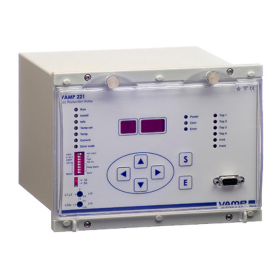
Manuals and User Guides for VAMP 221. We have
1
VAMP 221 manual available for free PDF download: Operation And Configuration Instructions. Technical Description
VAMP 221 Operation And Configuration Instructions. Technical Description (136 pages)
Arc protection system
Brand:
VAMP
| Category:
Protection Device
| Size: 3 MB
Table of Contents
Section 1
3
Table of Contents
3
General
4
VAMP 221 Arc Protection System Components
4
Central Unit VAMP 221
6
Arc Sensors VA 1 DA, VA 1 EH, ARC-Slx and VA
8
Other System Components
12
Operational Safety
13
User Interface
14
Display and Status Indications
15
Buttons and Programming Switches
16
Moving in Menus
17
I/O Unit Front Panels
18
VAM 10L - Front Panel
19
I/O Unit VAM 3L - Front Plate
20
I/O Unit VAM 3LX - Front Plate
21
I/O Unit VAM 4C - Front Plate
22
Multiplying Relay VAR 4CE - Front Plate
23
Multiplying Relay VAMP 4R - Front Plate
24
VAMP 221 Arc Protection System Operation and Troubleshooting
25
System Status Indications
25
Arc Fault
26
Overcurrent Alarm
27
Self-Supervision Alarm
29
Fault Codes
30
Using Programming Switches
36
Central Unit's Programming Switches
37
Programming Switches - I/O Units
38
Adjusting the Overcurrent Setting
41
Configuration of the Arc Protection System
43
Checking System Configuration
45
System Commissioning
46
Testing - General
46
Performing the Testing
47
Periodic Commissioning
47
Section 2
49
Introduction
52
Main Properties
52
Purpose
52
Arc (Fault) Protection (50AR)
54
Functions
54
Protection Functions
54
Circuit Breaker Failure Protection Stage (50BF)
56
Unbalance Alarm
56
Measurements
57
Output Relay Functions
57
BI/O Bus Interface
58
Self-Supervision
58
Connection to Another Central Unit
59
Connection to I/O Unit
60
Connection to Protection Relay
60
Application Examples
61
Selective Fibre Solution, 3 Incomers, 3 Protection Zones, CBFP in Use
61
Functional System Description
64
System Components
64
System Configuration
65
Testing of Example Application
69
Selective Sensor Solution, 2 Incomers, 2 Protection
71
Zones, CBFP in Use
71
Functional System Description
72
System Components
72
System Configuration
73
System Testing
76
Selective Fibre Sensor Solution, Multiple Incomers, Multiple Protection Zones, CBFP in Use
78
Functional System Description
80
System Components
81
System Configuration
82
System Testing
85
Arc Protection Current Measuring Based on Earth-Fault Current
87
Functional System Description
88
Interfaces
89
Rear Panel View
89
Analogue Measurements
91
Auxiliary Power Supply
92
Digital Inputs (BI/O Bus)
92
Output Relays
93
VAM 10L, VAM 3L, VAM 3LX and VAM 4C
93
Block Diagram
94
Vam 10L
95
Vam 3L / Vam 3Lx
95
Vam 4C
96
Vamp 4R
97
VAMP 221 Signaling Diagram
98
Connection Examples
99
Vam 10L
100
Connections
103
Measuring Circuits
103
Technical Data
103
Vam 3L / Vam 3Lx
103
Auxiliary Power Supply
104
Digital Inputs (BI/O Bus)
105
Trip Contacts
106
Alarm Contacts
107
Communication Bus Interface
108
Local Serial Communication Port
108
Tests and Environmental Conditions
108
Environmental Conditions
109
Mechanical Tests
109
Test Voltages
109
Casing
110
Package
110
Arc (Fault) Protection
111
Circuit Breaker Failure Protection Stage (50BF)
111
Protection Stages
111
Unbalance Alarm
111
Construction
112
Dimensional Drawings
112
Vam 10L / 3L / 3Lx / 4C , Vamp 4R
112
Va 1 da
113
Var 4Ce
113
Va 1 Eh
114
Vyx 001
114
Vyx 002
115
Vyx 076
116
Vyx 077
116
Unit Installation
117
Vam 10L, Vam 3L, Vam 3Lx, Vam 4C
120
Arc Sensors
122
Var 4 Ce
126
Vamp 4R
128
Order Information
131
Appendix/ Earthing Instruction
132
Reference Information
134
Advertisement
Advertisement
Related Products
VAMP VAMP 220
VAMP VAMP 220R
VAMP 257
VAMP 259
VAMP 265
VAMP 210
VAMP 260
VAMP 121
VAMP 121D
VAMP Categories
Relays
Protection Device
Adapter
Measuring Instruments
Control Unit
More VAMP Manuals
Login
Sign In
OR
Sign in with Facebook
Sign in with Google
Upload manual
Upload from disk
Upload from URL