Oki C9000 Series User Manual
Hide thumbs
Also See for C9000 Series:
- Printing manual (111 pages) ,
- Setup manual (62 pages) ,
- Brochure & specs (6 pages)
Table of Contents
Advertisement
Quick Links
Advertisement
Table of Contents
Troubleshooting

Related Manuals for Oki C9000 Series


Summary of Contents for Oki C9000 Series
- Page 1 C9800 USER’S GUIDE C9800 MFP/C9800 GA MFP C9000...
-
Page 2: Ontents Preface
Every effort has been made to ensure that the information in this document is complete, accurate, and up-to-date. OKI Printing Solutions assumes no responsibility for the results of errors beyond its control. OKI Printing Solutions also cannot guarantee that changes in software and equipment made by other manufacturers and referred to in this guide will not affect the applicability of the information in it. -
Page 3: Notes, Cautions And Warnings
OTES CAUTIONS AND WARNINGS NOTE A note provides additional information to supplement the main text. CAUTION! A caution provides additional information which, if ignored, may result in equipment malfunction or damage. WARNING! A warning provides additional information which, if ignored, may result in a risk of personal injury. AFETY WARNINGS This product has been carefully designed to give years of safe, reliable performance. - Page 4 WARNING! Ensure all warning and instruction labels on this product are read, understood and followed in order to prevent any risk of injury. Ensure this and all other documentation is both read carefully and retained for future reference. This product may be heavy. Please check the weight of this product and take all necessary precautions to prevent any risk of personnel injury.
- Page 5 WARNING! Keep this product away from direct heat sources such as radiators and out of direct sunlight to prevent any risk of overheating. The power supply required for this product is 220 - 240 VAC, 50/60 Hz. Refer to your product's rating label for full power rating details.
- Page 6 WARNING! If using an extension cable or power strip ensure that the total current rating (amperes) of all connected equipment is less than the maximum rating of the extension cable, power strip or wall outlet. Otherwise fire or shock may occur. If this product is already supplied with a fitted power strip then NO additional power strip or extension cable should be used to connect to...
- Page 7 WARNING! Always hold the power plug to connect/ disconnect the power cable to/from the mains socket. Unplugging by pulling on the cable can cause fraying and may lead to fire or electric shock. Use only the power cable and power strip supplied.
- Page 8 WARNING! If this product's casing gets extremely hot or smoke, unusual smells or abnormal noises are emitted from this product, there is a risk of fire. Unplug the mains connector and contact your dealer. If this product has been knocked over or damaged, there is a risk of electric shock, fire and/or injury.
- Page 9 WARNING! Do not use an extremely flammable spray near this product as the product contains high temperature parts that may cause a fire. Switch this product off before cleaning to prevent any risk of injury. Clean using a damp cloth. Do not use liquid or aerosol cleaners. Do not carry out any operations on this product that are not specified in the User's Guide.
- Page 10 WARNING! If items such as scanners or finishers are fitted, please exercise care when moving these items so as to avoid risk of entrapment or personnel injury. If this product is installed on a cabinet or high capacity feeder, ensure wheel locks are applied once it is placed in final position for use, to prevent risk of movement or injury.
- Page 11 Humidity: 20 to 80% RH The acoustic noise level of this product is 70 dB(A) or less according to EN ISO 7779. Imported into the EU by: Oki Europe Ltd (Trading as OKI Printing Solutions), Central House, Balfour Road, Hounslow,...
-
Page 12: Table Of Contents
ONTENTS Preface ........2 Notes, cautions and warnings! ....3 Safety warnings . - Page 13 Scanning ....... . 74 E-mail send mode ..... . . 74 Network send mode –...
- Page 14 Index ....... . . 201 Oki contact details ..... . . 203...
-
Page 15: Introduction
Spot-On and Hot Folder support (C9800 GA MFP only) > “Ask Oki” – a brand new, user-friendly function that gives a direct link from your printer driver screen (but not illustrated in this guide) to a dedicated web site specific to the exact model you are using. -
Page 16: About This Guide
BOUT THIS GUIDE NOTE Images used in this manual may include optional features that your product does not have installed. Also, they may omit features not essential to the description of a particular function. > This User’s Guide is your main user’s guide. Check the web site (see page 2) for the most up-to-date version. - Page 17 NLINE USAGE This guide is intended to be read on screen using an Adobe Acrobat Reader. Use the navigation and viewing tools provided in Acrobat. You can access specific information in two ways: > In the list of bookmarks down the left hand side of your screen, click on the topic of interest to jump to the required topic.
- Page 18 RINTING PAGES The whole manual, individual pages, or sections may be printed. The procedure is: From the toolbar, select [File], then [Print] (or press the Ctrl + P keys). Choose which pages you wish to print: [All pages], (1), for the entire manual. [Current page], (2), for the page at which you are looking.
-
Page 19: Mfp Overview
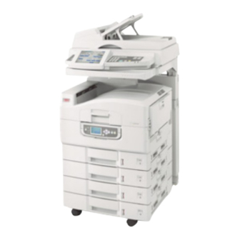
OVERVIEW DENTIFYING SYSTEM UNITS Printer unit (with high capacity feeder (HCF)) Scanner stand Scanner unit Finisher unit (optional accessory) C9800 MFP User’s Guide> 19... -
Page 20: Opening And Closing The Printer Unit Top Cover
PENING AND CLOSING THE PRINTER UNIT TOP COVER Operate the scanner stand lever (1) then raise the scanner to the limit of its travel. Ensure the stand is locked into position. To open the top cover, squeeze the top cover handle (1) to release the catch and raise the cover. - Page 21 To close the top cover, push gently (1) until the cover stops midway and then push harder (2) to close the cover completely. Ensure that the cover is securely closed. Operate the scanner stand lever (1) then guide the scanner to its lowest point. Ensure the stand locks into position.
-
Page 22: Identifying Major Components
DENTIFYING MAJOR COMPONENTS RINTER UNIT The major components of your printer unit are identified in the representations below. Paper holding arm Top cover (face-down stacker) MP Tray (multi-purpose tray) Tray 1 side cover Paper size label Paper volume indicator Tray 1 (paper tray) Control panel Top cover handle C9800 MFP User’s Guide>... - Page 23 Face-down stacker Power (on/off) switch Face-up stacker Duplex unit C9800 MFP User’s Guide> 23...
- Page 24 Interface unit Network interface connector Parallel interface connector USB interface connector NOTE The three connectors at 17a are for printer unit to scanner unit interconnection. Power connector Ventilation holes C9800 MFP User’s Guide> 24...
- Page 25 Image drum cartridge and toner cartridge (Cyan) Image drum cartridge and toner cartridge (Magenta) Image drum cartridge and toner cartridge (Yellow) Image drum cartridge and toner cartridge (Black) Toner cartridge Image drum cartridge Fuser unit LED heads C9800 MFP User’s Guide> 25...
- Page 26 Belt unit Drum basket handle Drum basket C9800 MFP User’s Guide> 26...
- Page 27 High capacity Feeder (HCF) 3 trays C9800 MFP User’s Guide> 27...
- Page 28 CANNER UNIT The major components of your scanner unit are identified in the representations below. Front view Automatic document feeder (ADF) front cover ADF paper tray ADF paper support Document cover Control panel Touch screen display C9800 MFP User’s Guide> 28...
-
Page 29: Software Supplied
Back view ADF paper tray, for multi-page documents ADF cable, to connect the ADF to the main unit Display port, to connect to printer unit Control port, to connect to printer unit ADF port, to connect the ADF cable Data port, to connect to printer unit Power jack, to connect to a power source Power switch, to turn the scanner on/off OFTWARE SUPPLIED... -
Page 30: Printer Unit
> CD3 – User’s Guides Contains documentation in electronic form (for example, the User’s Guide and Printing Guide) to describe how to use the MFP for day-to-day tasks. RINTER UNIT APER RECOMMENDATIONS Your printer unit will handle a variety of print media, including a range of paper weights and sizes, transparencies and envelopes. - Page 31 APER INPUT AND OUTPUT INFORMATION The following table relates paper parameters to input trays (Tray 1 to Tray 4 (numbering from the top) and MP Tray) and to output areas (Face-down stacker and Face-up stacker). TYPE SIZE WEIGHT INPUT/ OUTPUT Plain paper A3, A3 Nobi, A3 Wide, 64 –...
- Page 32 TYPE SIZE WEIGHT INPUT/ OUTPUT Transparencies A4, Letter 0.1 – 0.11mm Tray 1 or MP Tray Glossy paper Face-up Stacker RAYS AND STACKERS Trays 1 to 4 Tray 1 is the standard blank paper input tray and can hold up to 530 sheets of 80g/m²...
- Page 33 Face-down stacker The face-down stacker on the top of the printer can hold up to 500 sheets of 80g/m² standard paper, and can handle paper stocks from 64 – 216g/m². Pages printed in reading order (page 1 first) will be sorted in reading order (last page on top, facing down).
- Page 34 RAY AND STACKER EXAMPLES Loading Trays 1 to 4 Tray 1 is used in the following example. Pull out the tray. Press the paper rear stopper tab (1) and adjust the tab to the required paper size. Fan the paper to be loaded then tap the edges of the stack on a flat surface to make it flush.
- Page 35 Load the paper (face down and top edge towards the right for letterhead paper), press the tab (2) on the paper guide and adjust the guides (3) for a snug fit to the paper. To avoid paper jams: > Do not leave space between the paper and the guides and rear stopper.
- Page 36 Gently push the tray back into the printer. Using the MP Tray Squeeze the handle (1) and open the multi-purpose tray. C9800 MFP User’s Guide> 36...
- Page 37 Fold out the paper support section and swivel out the extension supports (2). Adjust the paper guides (3) to the size of the paper being used. Fan the paper to be loaded then tap the edges of the stack on a flat surface to make it flush. C9800 MFP User’s Guide>...
- Page 38 Load the paper. > For single-sided printing on letterhead, load the paper into the multi-purpose tray with pre-printed side up and top edge into the printer unit. > For two-sided (duplex) printing on letterhead, load the paper with pre-printed side down and top edge away from the printer unit.
- Page 39 Using the stackers Face-down stacker When the face-up stacker (1) on the left side of the printer is closed (its normal position), paper is ejected to the face-down stacker on the top of the printer unit. Face-up stacker The face-up exit path is used for heavy paper (cardstock etc.), envelopes, transparencies, and labels.
- Page 40 Flip out the paper support (2). Swivel out the paper support extension (3). C9800 MFP User’s Guide> 40...
-
Page 41: Scanner Unit
CANNER UNIT APER RECOMMENDATIONS The ADF can handle up to 50 sheets of A3 paper, of weight 60 – 105g/m². The glass can handle paper sizes up to A3 and the document cover can be left open to accommodate book thickness. Use the glass and not the ADF for scanning documents that: have a smooth surface e.g. - Page 42 With the text face up, introduce the document far enough into the ADF to be able to adjust the paper guide (1) to centre the document in the ADF. Release the document gently into the ADF. Loading the document glass (flatbed) For documents of size A4, the following orientation is recommended: >...
- Page 43 Place your document with text face down on the glass, aligning it to the upper left corner of the glass. Close the document cover. C9800 MFP User’s Guide> 43...
-
Page 44: Control Panels
ONTROL PANELS Control of your MFP is via two control panels, one located on the printer unit and the other on the scanner unit. The two control panels are complementary to each other and work together as component parts of the overall system. For example, a message on the scanner unit control panel will redirect you to the printer control panel if the situation requires it. -
Page 45: Buttons And Lights
UTTONS AND LIGHTS The parts of the control panel are identified and briefly explained below: Shutdown/Restart button Press and hold down for a soft shutdown. You can then press this button again for a restart or use the Power switch to turn off the printer completely. Ready light On: indicates ready to print Flashing: indicates processing print data... -
Page 46: Display Panel Messages
Down-arrow button Enters menu mode and enables downward movement through the displayed list of menu items Back button Returns to the previous higher level menu item Enter button Enters menu mode and selects the menu item highlighted in the display panel Online button Switches between online (printer unit ready to receive data) and offline (printer unit not ready to receive data) - Page 47 In the Error state, the printer unit has encountered a problem and cannot continue printing until the user has intervened and removed the cause of the trouble. The top two lines of the display panel show the printer unit status. The bottom of the display panel normally shows a bar chart of the toner usage.
-
Page 48: Display Panel Messages
ELP MODE When an error has occurred, press the Help button. Information displays that will help you correct the error. ISPLAY ANEL MESSAGES The display panel messages, supplemented by the Help messages where appropriate, are intended to be self- explanatory. More information on typical messages is provided in “Appendix A –... -
Page 49: Scanner Unit Control Panel
Press the Enter button to select this Value. (If you are setting a parameter, ensure that an asterisk (*) appears beside the selected parameter Value.) Press the Online button to exit menu mode and return to the ready to print status. Refer to the section entitled “Getting started”... - Page 50 decrement the value of the feature. Pressing the Menu button confirms and sets the new value. Touch screen display Enables you to make selections associated with the copying and scanning functions by touching the screen to press selected buttons. The screen can be tilted up for ease of viewing by pulling on handle (4a) and it locks in position.
- Page 51 SETUP button Pressing this button selects setup mode for address books or reports, for example. (See “Appendix F – Scanner unit setup details” on page 190.) HELP button Pressing this button displays help information on the touch screen. ATTENTION light Flashes when operator attention is required e.g after a paper jam has occurred.
-
Page 52: Getting Started
ETTING STARTED This section provides information to help you get started with using your MFP. URNING CAUTION! Do not turn off the scanner unit while scanning is in progress. URNING Printer unit Press and hold down the Shutdown/Restart button (1) on the control panel to start the shutdown process. - Page 53 Scanner unit When the scanner unit display shows that shut down has been completed, turn off the scanner unit at the power switch (1). Use the On/Off switch to turn off the printer unit. Please wait as this may take a short time. C9800 MFP User’s Guide>...
- Page 54 URNING Scanner unit Turn on the scanner unit at the power switch (1). NOTE If the display panel shows that you can either turn off or restart the printer, press Shutdown/Restart to turn on the printer. If the printer is turned off (no power), use the On/Off switch to turn on the printer.
-
Page 55: Checking Current Settings
HECKING CURRENT SETTINGS Carry out the following steps to generate a Configuration report (Menu Map) to confirm that your printer unit is correctly configured. Ensure that there is A4 paper in Tray 1 (to be used in this operation). Ensure that the LCD panel indicates that the printer is ready to print. - Page 56 When connecting multiple printer units of the same type, they appear as *****, ***** (2), ***** (3), etc. These numbers depend on the order of connecting or turning on each printer unit. > Ethernet – For network cable connection. NOTE Interface cables are not supplied with your printer unit.
- Page 57 ONNECTING THE INTERFACE Do not connect the USB cable at this time. You will be instructed when to connect the USB cable when you run the Drivers CD, CD1. If you are connecting your printer unit directly to a stand alone computer proceed to the section entitled “Using the Drivers CD”.
- Page 58 Connect an Ethernet cable between the printer unit and an Ethernet hub. Note the position of the ferrite core on the network cable fitted close to the printer interface. Turn on the printer unit and then the computer. If your printer unit is to be installed as a network printer, please refer to the relevant section in the Configuration Guide for further details on how to configure the network connection before installing the printer drivers.
-
Page 59: Using The Drivers Cd
SING THE RIVERS Insert the Drivers CD into your computer and follow the on- screen instructions. You are prompted to follow a set of basic steps to configure the display panel language (for both printer unit and scanner unit), install drivers and other software and finally print a test page to check that your printer is operating correctly thus far. -
Page 60: Printing
RINTING For full details of how to use the printer unit and any optional accessories to print jobs efficiently and effectively, please refer to the Printing Guide. C9800 MFP User’s Guide> 60... -
Page 61: Scanner Unit Operating Information
CANNER UNIT OPERATING INFORMATION CCESS CONTROL If your Administrator has enabled access control on your scanner, it will automatically start up in access control mode. You will not be able to use it until you have provided a valid PIN and logged in. -
Page 62: Logging Out
Press the Login button (1) and the default Copy Mode screen appears, the scanner unit now being available to use. OGGING OUT When you have finished using the scanner unit, press the Logout button (1) to return to the access control screen. C9800 MFP User’s Guide>... -
Page 63: Status Monitoring
TATUS MONITORING See also “Appendix C – Scanner Unit Status” on page 181. The Status button (1) changes colour depending on the status of the MFP: > Blue: ready status > Orange: warning status > Red: Alarm status For detailed status information, press the Status button to display the status window. -
Page 64: Using The Help Facility
SING THE ELP FACILITY To obtain help, press the HELP button on the scanner unit control panel. Select a topic and then press the Go To button (1). Navigate and read the help information you need. At any time you can press the Maintenance button (1) to show the Dealer’s Information screen for dealer contact information, then press the Close button to return to the Help screen. -
Page 65: Avoiding Incompatibility Situations
VOIDING INCOMPATIBILITY SITUATIONS It is possible to request your MFP to carry out instructions that would involve media incompatibilities e.g. if you are copying an A4 original with the Reduce/Enlarge setting at 141% (A4 to A3) and the (printer unit) Tray Selection set at Tray 1 containing A4 media. -
Page 66: Copying
OPYING Documents to be copied are scanned in the scanner unit (document glass or ADF) and copies are automatically printed in the printer unit. Carry out the following steps: Copy Mode is the default function of the MFP. If required, press the COPY button on the scanner unit control panel to show the Copy Mode screen. -
Page 67: Basic Settings Tab
ASIC ETTINGS TAB FEATURE OPTIONS DESCRIPTION Copies 1-999 Allows you to specify the number of copies to be made. The maximum number of copies that can be set per job is 999. Original Size Auto, 5.5x8.5, Allows you to select the 5.5x8.5R, 8.5x11, paper size to match the 8.5x11R, 8.5x13,... - Page 68 FEATURE OPTIONS DESCRIPTION Lighter/Darker Auto, -5 to +5 by 1 Allows you to adjust the brightness levels for scanning and printing. This is not applied (disabled) if Auto Exposure is set to ON. Colour Mode Color, B&W Allows you to select the colour mode of the output.
-
Page 69: Details Tab
ETAILS TAB FEATURE OPTIONS DESCRIPTION Original Type Mixed, Text, Photo Allows you to specify the type of images on the document. This allows automatic (pre- set) optimization of image quality settings. N-up OFF, 2-Up, 4-Up, 8-Up Allows you to print multiple pages of the document to a single sheet of paper. - Page 70 FEATURE OPTIONS DESCRIPTION Book Copy 1 to 1 Side, Allows you to select Book to 1 side, how book copies are Book to 2 sides printed. If you specify Book to 1 side or Book to 2 sides, set your original document on the glass.
-
Page 71: Image Quality Tab
MAGE UALITY TAB FEATURE OPTIONS DESCRIPTION Sharpness -5 to +5 by 1 Allows you to enhance the image's outline, letters, lines when printing. Background OFF, 1 to 10 by 1 Allows you to block out Removal the colour background of the image (assuming document has a colour background) - such that the background colour... - Page 72 FEATURE OPTIONS DESCRIPTION Color -5 to +5 by 1 Allows you to adjust the Saturation overall colour saturation (neutrally across all colours) of the image. Color Saturation is not available where Color Mode is set to B&W or Color Presets is set to Vivid.
-
Page 73: Finishing Tab
INISHING TAB FEATURE OPTIONS DESCRIPTION Staple OFF / Left Position / Allows you to select the Right Position staple options (and sub- options) that will be applied to the document. Punch OFF / Left Position / Allows you to select the Right Position punching options (and sub-options) that will be... -
Page 74: Scanning
CANNING Your MFP can carry out the following scanning functions: > E-mail send mode (SCAN TO E-MAIL button) Scan to e-mail: An original document is scanned and the data is sent by e-mail as an attachment. > Network send mode (SCAN TO NETWORK button) Scan to FTP: An original document is scanned and the data is sent to an FTP server. - Page 75 Set your document on the scanner unit and press START. These steps are expanded below. Press the SCAN TO E-MAIL button to display the E-mail Send Mode screen at the Address tab Press the To button (1) and enter an e-mail address via one of the following buttons: >...
- Page 76 Address Book Touch on an e-mail address to select it. Press the Add button (1) to add this address to the list. Repeat (a) and (b) as required to create the address list. Press the OK button (2) to place the list of addresses in the To destination field.
- Page 77 LDAP Press the User ID button (1) and enter your user ID via the soft keyboard then press the OK button. Press the Password button (2) and enter your password via the soft keyboard then press the OK button. Press the Next button (3). C9800 MFP User’s Guide>...
- Page 78 Press either the User Name (1) or Mail button (2) to enter your search value via the soft keyboard, then press the OK button. Press the Next button (3). Select an address from the list displayed and press the Add button (4) to add this address to your destination list.
- Page 79 Soft Keyboard Enter an address via the soft keyboard. Press the Add button (1) to add this address to the list. Repeat (a) and (b) as required to create the address list. Press the OK button (2) to place the list of addresses in the To destination field.
- Page 80 Fax Gateway Press the Fax Number button (1), enter a fax number via the soft keyboard, then press the OK button. Press the Recipient Name button (2), enter a recipient name via the soft keyboard, then press the OK button. Press the OK button (3).
- Page 81 Touch the Message Text tab, press the Edit Message button (1), enter your e-mail message via the soft keyboard and press the OK button. C9800 MFP User’s Guide> 81...
- Page 82 Touch the Attachments tab. Press the File Name button (1) and enter a name for your scanned file via the soft keyboard then press the OK button. Use the following features as required: Resolution (2) (150, 200, 300, 400, 600dpi) Color Mode (3) (Color, Grayscale, B/W) File Format (4) (JPEG, PDF, TIFF) Sides (5) (Single, Top/Top, Top/Bottom)
- Page 83 Select from the following features as required: FEATURE OPTIONS DESCRIPTION Original Size Auto, 5.5x8.5, Allows you to select the 5.5x8.5R, 8.5x11, scanned document size. 8.5x11R, 8.5x13, 8.5x14, 11x17, A5, A5R, A4, A4R, A3, B5, B5R, B4 Original Type Mixed, Text, Photo Allows you to specify the type of images on the document.
- Page 84 FEATURE OPTIONS DESCRIPTION Edge/Center OFF / Edge Allows you to block out Erase Metric: 0-50mm in the peripheral areas of 1mm increments the document where Inch: 0" – 2.0" in 0.1" spurious shadows and increments borders may arise when scanning with the document cover open (such as with books and magazines) or for other...
-
Page 85: Network Send Mode - Scan To Ftp
– ETWORK SEND MODE SCAN TO The main steps in summary are: Press the SCAN TO NETWORK button. Press the FTP Server button (set by default). On the FTP Server tab, enter the FTP Server name. On the Attachments tab, define your attachment properties, using the Advanced Settings features as required. - Page 86 Server List Touch on an FTP server name to select it. Press the OK button (1) to place the name in the FTP Server Name box on the FTP Server tab. C9800 MFP User’s Guide> 86...
- Page 87 Soft Keyboard Use the soft keyboard and respective buttons to enter the following host information: Basic Information tab: Server name (1), Path (2), User Name (3), Password (4) Extensions tab: Port Number (1), Timeout (2), Retries (3), Interval (4) C9800 MFP User’s Guide> 87...
- Page 88 Proxy Information tab: Server Name (1), User Name (2), Password (3), Port Number (4) Press the OK button (5) to enter the data and place the name in the FTP Server Name box on the FTP Server tab. C9800 MFP User’s Guide> 88...
- Page 89 Touch the Attachments tab. Press the File Name button (1) and enter a name for your scanned file via the soft keyboard then press the OK button. Use the following features as required: Resolution (2)(150, 200, 300, 400, 600dpi) Color Mode (3)(Color, Grayscale, B/W) File Format (4)(JPEG, PDF, TIFF) Sides (5) (Single, Top/Top, Top/Bottom) Allows you to define simplex or duplex and the...
- Page 90 Select from the following features as required: FEATURE OPTIONS DESCRIPTION Original Size Auto, 5.5x8.5, Allows you to select the 5.5x8.5R, 8.5x11, scanned document size. 8.5x11R, 8.5x13, 8.5x14, 11x17, A5, A5R, A4, A4R, A3, B5, B5R, B4 Original Type Mixed, Text, Photo Allows you to specify the type of images on the document.
- Page 91 FEATURE OPTIONS DESCRIPTION Edge/Center OFF / Edge Allows you to block out Erase Metric: 0-50mm in the peripheral areas of 1mm increments the document where Inch: 0" – 2.0" in 0.1" spurious shadows and increments borders may arise when scanning with the document cover open (such as with books and magazines) or for other...
-
Page 92: Remote Scan Mode
EMOTE SCAN MODE The main steps in summary are: Press the SCAN TO NETWORK button. Press the Remote Tool button. Set your document on the scanner unit. Press the On Line button. After the document has been scanned under control of the remote PC, the status returns to Off Line automatically. -
Page 93: Mailbox Send Mode
AILBOX SEND MODE In the context of this section, dealing with scan to mailbox and scan to hold queue functions, the following table summarises mailbox and hold queue properties. PROPERTY MAILBOX HOLD QUEUE Description Simple file server in the A print queue in the printer unit hard disk printer unit hard disk drive. - Page 94 These steps are expanded below. Press the SCAN TO MAILBOX button to display the Mailbox Send Mode screen. Press the Mailbox button (1) (set by default). On the Mailbox tab, enter the Mailbox name via one of the following buttons: >...
- Page 95 Mailbox List Press the Mailbox List button. Touch a mailbox name to select it. Press the OK button (1) to begin to enter the name in the Mailbox Name box on the mailbox tab. To see a list of the files in the selected mailbox, press the File List button (2).
- Page 96 Direct Search Press the Direct Search button. Use the soft keyboard to enter a mailbox name then press the OK button (1). Use the soft keyboard to enter the associated mailbox password button then press the OK button. C9800 MFP User’s Guide> 96...
- Page 97 New Mailbox Press the New Mailbox button. Press the Mailbox Name button (1), enter a name for the new mailbox via the soft keyboard then press the OK button. Press the Password button (2), enter a password for the new mailbox via the soft keyboard then press the OK button.
- Page 98 Touch the Attachments tab. Press the File Name button (1) and enter a name for your scanned file via the soft keyboard then press the OK button. Use the following features as required: Resolution (2) (150, 200, 300, 400, 600dpi) Color Mode (3) (Color, Grayscale, B/W) Sides (4) (Single, Top/Top, Top/Bottom) Allows you to define simplex or duplex and the...
- Page 99 Select from the following features as required: FEATURE OPTIONS DESCRIPTION Original Size Auto, 5.5x8.5, Allows you to select the 5.5x8.5R, 8.5x11, scanned document size. 8.5x11R, 8.5x13, 8.5x14, 11x17, A5, A5R, A4, A4R, A3, B5, B5R, B4 Original Type Mixed, Text, Photo Allows you to specify the type of images on the document.
- Page 100 FEATURE OPTIONS DESCRIPTION Edge/Center OFF / Edge Allows you to block out Erase Metric: 0-50mm in the peripheral areas of 1mm increments the document where Inch: 0" – 2.0" in 0.1" spurious shadows and increments borders may arise when scanning with the document cover open (such as with books and magazines) or for other...
- Page 101 Press the START button on the Scanner Unit control panel. These steps are expanded below. Press the SCAN TO MAILBOX button to display the Mailbox Send Mode screen. Press the Hold Queue button (1). On the Hold Queue tab (2), check the displayed settings for your scanned file.
- Page 102 Touch the Attachments tab. Press the File Name button (1) and enter a name for your scanned file via the soft keyboard then press the OK button. Use the following features as required: Resolution (2) (150, 200, 300, 400, 600dpi) Color Mode (3) (Color, Grayscale, B/W) Sides (4) (Single, Top/Top, Top/Bottom) Allows you to define simplex or duplex and the...
- Page 103 Select from the following features as required: FEATURE OPTIONS DESCRIPTION Original Size Auto, 5.5x8.5, Allows you to select the 5.5x8.5R, 8.5x11, scanned document size. 8.5x11R, 8.5x13, 8.5x14, 11x17, A5, A5R, A4, A4R, A3, B5, B5R, B4 Original Type Mixed, Text, Photo Allows you to specify the type of images on the document.
- Page 104 FEATURE OPTIONS DESCRIPTION Edge/Center OFF / Edge Allows you to block out Erase Metric: 0-50mm in the peripheral areas of 1mm increments the document where Inch: 0" – 2.0" in 0.1" spurious shadows and increments borders may arise when scanning with the document cover open (such as with books and magazines) or for other...
-
Page 105: Consumables And Maintenance - Printer Unit
– ONSUMABLES AND MAINTENANCE PRINTER UNIT This section explains how to replace consumable and maintenance items when due. As a guide, the life expectancy of these items is: > Toner — 15,000 A4 pages at 5% coverage. The printer unit is shipped with sufficient toner for 7,500 A4 pages in the print cartridges of which 1 –... -
Page 106: Consumable Item Order Information
ONSUMABLE ITEM ORDER INFORMATION ITEM LIFE ORDER NUMBER Toner, Black 15,000 A4 pages @ 5% 42918916 Toner, Cyan 15,000 A4 pages @ 5% 42918915 Toner, Magenta 15,000 A4 pages @ 5% 42918914 Toner, Yellow 15,000 A4 pages @ 5% 42918913 Toner, rainbow pack 15,000 A4 pages @ 5% 43112702... -
Page 107: Replacing Consumables/Maintenance Items
You are advised to follow these instructions carefully. CAUTION! Only use genuine OKI Printing Solutions original consumables to ensure the best quality and performance from your hardware. Non-Oki Original products may damage your printer unit’s performance and invalidate your warranty. - Page 108 With an LED lens cleaner or soft cloth, gently wipe each of the four heads (1). Move the cleaner as shown, using a clean section of the cleaner with each pass. Be careful not to damage the guards (2). Close the printer unit top cover then lower the scanner unit.
-
Page 109: Cleaning The Paper Feed Rollers
LEANING THE PAPER FEED ROLLERS Clean the paper feed rollers if paper jams frequently occur. Remove items like a wrist watch or bracelet then use the Shutdown/Restart button followed by the On/Off switch to turn the printer unit off. C9800 MFP User’s Guide> 109... - Page 110 Open Tray 1 side cover and pull out the paper guide plate (1). Remove Tray 1 completely from the printer unit. C9800 MFP User’s Guide> 110...
- Page 111 Gaining access through the gap left by Tray 1, wipe the 3 paper feed rollers (2) with a soft cloth lightly moistened with water. Replace Tray 1. C9800 MFP User’s Guide> 111...
- Page 112 Return the paper guide plate to its original position and close Tray 1 side cover. Turn on the printer unit. C9800 MFP User’s Guide> 112...
-
Page 113: Cleaning The Printer Unit Casing
LEANING THE PRINTER UNIT CASING Turn the printer unit off by using the Shutdown/Restart button followed by the On/Off switch. Wipe the printer unit surface with a soft cloth moistened sparingly with water or neutral detergent. Use a soft dry cloth to dry the printer unit surface. C9800 MFP User’s Guide>... -
Page 114: Emptying The Punch Chip Box
Turn on the printer unit. MPTYING THE PUNCH CHIP BOX (Punch unit optional accessory) When the display panel indicates that the punch chip box is full, empty the box as follows: Operate the Finisher lever and move the Finisher away from the printer unit. - Page 115 Pull out the punch chip box, being careful to keep it level so as not to spill any chips. Discard the chips in an appropriate place. Replace the punch chip box carefully into the Finisher. C9800 MFP User’s Guide> 115...
- Page 116 Check that the punch chip box has been replaced correctly then move the Finisher back into position, being careful not to trap your fingers. C9800 MFP User’s Guide> 116...
-
Page 117: Maintenance - Scanner Unit
– AINTENANCE SCANNER UNIT LEANING THE From time to time the pad assembly and feed rollers may become contaminated with ink, toner particles or paper dust. In this case the scan module may not feed documents smoothly. If this occurs, follow the cleaning procedure below. Moisten a cotton swab with isopropyl alcohol (95%). -
Page 118: Cleaning The Touch Screen Display
LEANING THE OUCH CREEN ISPLAY CAUTION! Be careful not to stress or damage the touch screen display. To clean the display surface, use a soft cloth, either dry or moistened with neutral detergent or ethanol. Do not use any organic solvents, acid or alkali solutions. LEANING THE DOCUMENT GLASS The document glass needs to be cleaned occasionally to ensure optimum image quality and performance. -
Page 119: Replacing The Snap-In Pad Module
Close the document cover (1). Your machine is now ready for use. EPLACING THE SNAP IN PAD MODULE After scanning approximately 100,000 pages through the ADF, the pad may become worn and you may experience problems with document feeding. In this case, you are recommended to replace the pad module by a new one. - Page 120 Press both arms of the ADF snap-in pad module inward with your fingers and pull out the ADF snap-in pad module. NSERTING A NEW SNAP IN PAD MODULE Remove the new snap-in pad module from its box. Press both arms of the snap-in pad module (2) inward using two fingers.
- Page 121 Push the snap-in pad module into the hole until it snaps into place. C9800 MFP User’s Guide> 121...
-
Page 122: Optional Accessories
PTIONAL ACCESSORIES This section describes optional accessory equipment for your MFP. The following accessories are available: > Finisher (for stapling or saddle stitching printer output) > Punch unit (to extend Finisher functionality) CCESSORY ORDER INFORMATION ITEM ORDER NUMBER Finisher: 4-tray 01166701 Finisher Punch Unit: 4 hole... -
Page 123: Troubleshooting
ROUBLESHOOTING ENERAL If the printer unit display panel does not display anything or is still in standby mode 10 minutes after switching on, follow the printer unit shutdown sequence (page 52) to switch it off. Check all cable connections before restarting the printer unit. If the problem persists, contact your dealer. - Page 124 Squeeze the catch (1) on Tray 1 side cover and open the cover. Holding it by the tab (2), turn the paper guide outward. Carefully remove the jammed paper. C9800 MFP User’s Guide> 124...
- Page 125 Put the paper guide back into position and close Tray 1 side cover. PEN COVER PAPER JAM SIDE COVER If the MP Tray is open, close it so that the side cover (1) is visible. C9800 MFP User’s Guide> 125...
- Page 126 Pull the release lever (2) and pull open the side cover. Carefully remove the jammed paper. C9800 MFP User’s Guide> 126...
- Page 127 Close the side cover. PEN COVER PAPER JAM TOP COVER Raise the scanner unit, squeeze the printer unit top cover handle (1) and open the top cover. WARNING Be careful not to touch the fuser unit which is hot after printing.
- Page 128 Squeeze the basket handle (2) and raise the drum basket. Carefully remove any paper on the belt. If paper is jammed in the fuser unit, push the lock lever (3) in the direction shown to release the unit. WARNING Be careful not to touch the fuser unit which may be hot after printing.
- Page 129 Holding the fuser unit (4) by the handle, lift it out of the printer unit and place it on a flat surface. Pull up the jam release levers (5) and remove the jammed paper. C9800 MFP User’s Guide> 129...
- Page 130 Carefully replace the fuser unit into the printer unit and turn the lock lever (6) in the direction shown to lock the fuser unit. If paper is jammed near the paper exit, open the face-up stacker (7). C9800 MFP User’s Guide> 130...
- Page 131 Open the side cover (paper exit) (8) and remove the jammed paper. Close the side cover (paper exit) and then the face-up stacker. C9800 MFP User’s Guide> 131...
- Page 132 Return the image drum basket (9) into position and check it is locked. Close the printer unit top cover and ensure it is latched, then lower the scanner unit. C9800 MFP User’s Guide> 132...
-
Page 133: Paper Jams - Duplex Unit
– APER JAMS DUPLEX UNIT HECK DUPLEX UNIT PAPER JAM If a Finisher unit is attached to your printer unit, operate the lever (1) of the Inverter unit to separate the Inverter from the printer. C9800 MFP User’s Guide> 133... - Page 134 Operate the duplex cover release button (2) and open the cover. Carefully remove any jammed paper then close the cover. C9800 MFP User’s Guide> 134...
- Page 135 Operate the levers (3) and pull out the duplex unit. Holding the front top cover by the grip (4), push it gently inwards and raise it. C9800 MFP User’s Guide> 135...
- Page 136 Remove any jammed paper. In similar manner, check for and clear any paper jammed under the rear top cover. C9800 MFP User’s Guide> 136...
- Page 137 Replace the two top covers. Push the duplex unit back into position. C9800 MFP User’s Guide> 137...
- Page 138 If you detached a Finisher unit to gain access to the duplex unit, replace the Finisher unit. C9800 MFP User’s Guide> 138...
-
Page 139: Paper Jams - Finisher (Optional Accessory)
– F APER JAMS INISHER OPTIONAL ACCESSORY HECK INISHER PAPER JAM PAPER REMAINS Use the Help button on the printer unit control panel to check the number displayed. You will need this to be able to clear the paper jam. The following paragraphs explain what to do for each of the indicated numeric codes. - Page 140 Open the Finisher top cover. Carefully remove any jammed paper. Close the Finisher top cover. C9800 MFP User’s Guide> 140...
- Page 141 Move the Finisher back into position and connect it to the Inverter. 594, 597, 598/ 644, 646 ( PAPER JAM IN INISHER Operate the Finisher lever (1) and move the Finisher away from the Inverter. C9800 MFP User’s Guide> 141...
- Page 142 Open the Finisher front cover (2). Continue to turn the lower knob (3) clockwise until any jammed paper is completely ejected. Remove the ejected paper. C9800 MFP User’s Guide> 142...
- Page 143 Close the Finisher front cover. Open the Finisher right side cover. Carefully remove any jammed paper. C9800 MFP User’s Guide> 143...
- Page 144 Close the Finisher right side cover. Move the Finisher back into position and connect it to the Inverter. C9800 MFP User’s Guide> 144...
- Page 145 590 ( PAPER JAM IN INISHER UNCH UNIT Operate the Finisher lever (1) and move the Finisher away from the Inverter. Move the tab (2) on the right side of the Finisher to align it with the mark (3). Open the Finisher top cover. C9800 MFP User’s Guide>...
- Page 146 Carefully remove any jammed paper. Close the Finisher top cover. Move the Finisher back into position and connect it to the Inverter. C9800 MFP User’s Guide> 146...
- Page 147 HECK NVERTER PAPER JAM Operate the Finisher lever (1) and move the Finisher away from the Inverter. Squeeze the recessed handle (2) and open the left side cover of the Inverter. C9800 MFP User’s Guide> 147...
- Page 148 Carefully remove any jammed paper. Close the Inverter left side cover. Move the Finisher back into position and connect it to the Inverter. C9800 MFP User’s Guide> 148...
- Page 149 Operate the Inverter lever (3) and separate the Inverter from the printer. Open the right side door (4) of the Inverter. C9800 MFP User’s Guide> 149...
- Page 150 Remove any jammed paper. Close the right side door. Move the Finisher and Inverter back into position and connect to the printer unit. C9800 MFP User’s Guide> 150...
-
Page 151: Avoiding Printer Unit Paper Jams
VOIDING PRINTER UNIT PAPER JAMS The following table summarizes possible causes of paper jams and suggests ways of avoiding them. POSSIBLE CAUSE SUGGESTED REMEDY The printer unit is not level. Ensure the printer unit is level. Your print media is too light or Use appropriate media. -
Page 152: Dealing With Unsatisfactory Printing
EALING WITH UNSATISFACTORY PRINTING SYMPTOMS POSSIBLE CAUSES STEPS TO TAKE Vertical white lines The LED head is dirty. Wipe the LED head with a can be seen on the LED lens cleaner or with a printed page. soft cloth. The toner is low. Replace the toner cartridge. - Page 153 SYMPTOMS POSSIBLE CAUSES STEPS TO TAKE Vertical lines The image drum Replace the image drum appear. cartridge is damaged. cartridge. The toner is low. Replace the toner cartridge. Horizontal Lines When the interval is Wipe it lightly with a soft and spots appear about 94mm (4in), the cloth.
-
Page 154: Paper Jams - Adf
– ADF APER JAMS To clear a paper jam in the ADF: Press down the ADF Release button (1). Gently open the ADF front cover (2). Carefully pull the paper out of the ADF. If there is paper jammed at the ADF exit area, open the ADF document cover, operate the coloured release lever situated on the underside of the cover at (3) and carefully pull out the jammed paper. -
Page 155: Staple Jams - Finisher Optional Accessory
– F TAPLE JAMS INISHER OPTIONAL ACCESSORY HECK INISHER TAPLE When the printer unit display indicates a staple jam has occurred, clear the jam as follows: Open the Finisher front cover. Turn the knob in the direction indicated until the coloured indicator appears. - Page 156 Remove any paper that awaits stapling in the paper ejection area. Pull out the staple unit. C9800 MFP User’s Guide> 156...
- Page 157 Turn the knob in the direction indicated to move the stapler to the front. Grip both sides of the staple cartridge, pull it up and remove it. Raise the staple cartridge gate. C9800 MFP User’s Guide> 157...
- Page 158 Remove all staples that are emerging from the staple case. Return the staple cartridge gate to its original position. Replace the staple cartridge. C9800 MFP User’s Guide> 158...
- Page 159 Ensure that the staple cartridge is securely installed back into the staple unit then push the staple unit fully home. Close the Finisher front cover, being careful not to trap your fingers. C9800 MFP User’s Guide> 159...
-
Page 160: Specifications
PECIFICATIONS RINTER UNIT ITEM SPECIFICATION Dimensions 655x620x462mm (WxDxH) Weight Without options, 68kg Print speeds 36 ppm colour; 40 ppm monochrome Resolution 1200 x 1200 dpi Emulations PCL 5c, PCL XL 2.1, PS Memory 1 GB (max.) Paper input Trays 1 – 4: 530 sheets A4 each at 80g/m²... -
Page 161: Scanner Unit
ITEM SPECIFICATION Noise level Operating: 53dBA maximum Standby: 40dBA maximum Power save: 40dBA maximum after 30 mins background level Machine Noise Information Ordinance 3. GSGV 18.1.1991: The maximum sound pressure level is equal to or less than 70dBA according to ISO 7779. CANNER UNIT ITEM SPECIFICATION... -
Page 162: (Printer)
A – D PPENDIX ISPLAY ANEL ESSAGES RINTER The display panel messages are intended to be self-explanatory. Representative messages are given as examples below. MESSAGE COMMENT Ready to Print Your printer unit is online and ready to print. Printing tttttt Your printer unit is printing and paper is currently being fed from tttttt, where tttttt identifies a tray. - Page 163 MESSAGE COMMENT Open Cover Additional paper has been detected after a paper Paper Remains jam has been cleared. tttttt Open tttttt side cover to check for additional paper. Please see HELP for You can access help details by pressing the HELP details button.
-
Page 164: Appendix B - Menu System (Printer Unit)
B – M PPENDIX ENU SYSTEM RINTER UNIT The top-level Functions menus are: > Configuration > Print Pages > Suspend Printing > Resume Printing > Print Secure Job > Menus > Shutdown > Admin Setup > Calibration > Print Statistics The other special top-level menu is: >... -
Page 165: Configuration
ONFIGURATION RINT OUNT ITEM VALUE DESCRIPTION Colour Page nnnnnn Displays number of colour printed pages converted to A4 equivalent. Monochrome nnnnnn Displays number of Page monochrome printed pages converted to A4 equivalent. Traym nnnnnn Displays total printed pages from Traym, where m is in range 1 to MP Tray nnnnnn... - Page 166 UPPLIES ITEM VALUE DESCRIPTION xxxx Drum Remaining nnn% Displays the remaining life span of the xxxx drum as a percentage where xxxx can be Cyan, Magenta, Yellow, Black. Belt Remaining nnn% Displays the remaining life span of the belt unit as a percentage.
- Page 167 APER IZE IN ITEM VALUE DESCRIPTION Traym where Executive Displays detected paper m is in range 1 Letter Short Edge size of Traym. to 4 Letter Long Edge Legal 14 (similar Legal 13.5 arrangement Tabloid for all trays) Tabloid Extra Legal 13 A4 Short Edge A4 Long Edge...
- Page 168 ITEM VALUE DESCRIPTION Total Memory xx MB Displays total RAM memory installed in the printer. Same as Total Memory of Menu Map. xx.xx GB [Fxx] Displays size of hard disk and file system version. Same as HDD of Menu Map. –...
-
Page 169: Print
Demo Page Execute Prints a demo page. Usage Report Execute Prints usage report. Statistics Log Execute Prints Oki job log details. Error Log Execute Prints the error log. E-mail Log Execute Prints e-mail log. PrintMe Log Execute Prints PrintMe Log. -
Page 170: Print Secure Job
– RINT NFORMATION EXAMPLE DEMONSTRATION PAGE To print a demo page to demonstrate how your printer unit prints: Ensure that the display panel indicates that the printer unit is ready to print. Enter menu mode by pressing either the Up-arrow or Down-arrow button and press them repeatedly until the Print Pages menu is highlighted. -
Page 171: Menus
ENUS ONFIGURATION ITEM VALUE DESCRIPTION Paper Feed Tray1 Specifies a feed tray. Tray2 Tray3 Tray4 MP Tray Auto Tray Sets the automatic tray Switch switch function. Tray Sequence Down Specifies selection order priority for Paper feed tray automatic tray selection/automatic tray switch. - Page 172 ITEM VALUE DESCRIPTION Traym Config, Media Weight Auto Sets media weight for where m is in Light Traym. range 1 to 4 Medium Light Medium (similar Medium Heavy arrangement Heavy for all trays) Ultra Heavy 1 Ultra Heavy 2 Ultra Heavy 3 A3 Nobi A3 Nobi The printer detects A3...
- Page 173 ITEM VALUE DESCRIPTION MP Tray Config Paper Size A3 Nobi Sets paper size for MP A3 Wide Tray. A4 Sht Edge A4 Long Edge B5 Short Edge B5 Long Edge Legal 14 Legal 13.5 Tabloid Extra Tabloid Letter Sht Edge Letter Long Edge (L) Executive...
- Page 174 ITEM VALUE DESCRIPTION MP Tray Config Media Type Plain Sets the media type for Letterhead MP Tray. Transparency Labels Bond Recycled Card stock Rough Glossy Envelope User Type1 User Type2 User Type3 User Type4 User Type5 Media Weight Auto Sets the media weight Light for MP Tray.
- Page 175 YSTEM DJUST ITEM VALUE DESCRIPTION Power Save 5 min Sets the period after Time 15 min which power save 30 min mode starts. 60 min 240 min Clearable Online When Online is Warning selected, you must manually clear the warning by pressing the Online button.
- Page 176 ITEM VALUE DESCRIPTION Low Toner Continue Sets the printing Stop operation when insufficient toner is detected. Continue: the printer can continue printing while remaining online. Stop: the printer stops printing and goes offline. Jam Recovery ON: continues printing the job, including any jammed pages, once the jam has been cleared.
- Page 177 ITEM VALUE DESCRIPTION Print Position Duplex X Adjust 0.00 During the flip-side Adjust +0.25 – +2.00 printing of duplex -2.00 – -0.25 printing, adjusts the location of the whole printing image (0.25 0.00 mm, 0.01in interval) +0.01 – +0.08 perpendicular to the -0.08 –...
- Page 178 ITEM VALUE DESCRIPTION Paper Black Used for micro Setting +1 – +2 adjustment when -2 – -1 very visible faded print results or light specks (or streaks) result when printing in Plain Paper/Black setting. Decrease the value if light specks (or streaks) or snow flake like printing results in high density print...
- Page 179 1 – T ENUS EXAMPLE TRANSPARENCIES To print on transparencies (accommodated in Tray1): Ensure that the display panel indicates that the printer unit is ready to print. Enter menu mode by pressing either the Up-arrow or Down-arrow button and press them repeatedly until the Menus menu is highlighted.
- Page 180 2 – MP T ENUS EXAMPLE RAY PAPER SIZE To set paper size in the MP Tray: Ensure that the display panel indicates that the printer unit is ready to print. Enter menu mode by pressing either the Up-arrow or Down-arrow button and press them repeatedly until the Menus menu is highlighted.
-
Page 181: Appendixc - Scanner Unit Status
C – S PPENDIX CANNER TATUS The scanner unit display panel is intended to be self explanatory and provides textual status information and help information (if appropriate) for both the scanner unit and the printer unit. A scanner image is also provided to help indicate where a scanner unit problem has occurred. -
Page 182: Appendixd - Media Support Information
D – M PPENDIX EDIA SUPPORT INFORMATION The following tables should be read together and define media sizes in allowable input and output combinations, including Finisher unit punching and stapling options. Explanations of terms used in the table headings are: >... - Page 183 Symbols used in the table bodies are: > Y: Supported i.e. allowable by the MFP Y1: Media ejection possible, but no print guarantee Y2: Short Edge Feed (SEF) only Y3: Media output route is limited by size and an error message may result Y4: Feed direction is determined by the print orientation (Portrait/Landscape) and the N-up setting...
-
Page 184: Input Locations
NPUT LOCATIONS MEDIA SIZE Letter Legal 14in Legal 13.5in Legal 13in Executive Tabloid Tabloid Extra A3 Nobi A3 Wide Index card Com-10 Com-9 Monarch Custom A4LEF A4SEF C9800 MFP User’s Guide> 184... -
Page 185: Printer Unit Output Locations
MEDIA SIZE B5LEF B5SEF Letter LEF Letter SEF RINTER UNIT OUTPUT LOCATIONS MEDIA SIZE Letter Legal 14in Legal 13.5in Legal 13in Executive Tabloid Tabloid Extra A3 Nobi A3 Wide Index card C9800 MFP User’s Guide> 185... -
Page 186: Finisher Unit Output Locations
MEDIA SIZE Com-10 Com-9 Monarch Custom A4LEF A4SEF B5LEF B5SEF Letter LEF Letter SEF INISHER UNIT OUTPUT LOCATIONS MEDIA SIZE Letter Legal 14 C9800 MFP User’s Guide> 186... - Page 187 MEDIA SIZE Legal 13.5 Legal 13 Executive Tabloid Tabloid Extra A3 Nobi A3 Wide Index card Com-10 Com-9 Monarch Custom A4LEF A4SEF B5LEF B5SEF Letter Letter C9800 MFP User’s Guide> 187...
-
Page 188: Appendixe - Auto Detection Paper Sizes
E – A PPENDIX UTO DETECTION PAPER SIZES The following tables define which document sizes can be scanned (flatbed or ADF) when using the Auto setting. NOTE (a) settings are mutually exclusive with (b) settings and cannot be changed by the user. Changing between a (c) or (d) setting can be carried out by the user. -
Page 189: Adf
PAPER TYPE PAPER SIZE (MM) PAPER SIZE (INCH) 297 x 420 11.69 x 16.54 A4 (SEF) (a) 210 x 297 8.27 x 11.69 A4 (LEF) 297 x 210 11.69 x 8.27 A5 (SEF) (a) 148 x 210 5.83 x 8.27 B4 (SEF) 257 x 364 10.12 x 14.33... -
Page 190: Appendixf - Scanner Unit Setup Details
F – S PPENDIX CANNER UNIT SETUP DETAILS This section provides an overview of the setup facilities on your scanner unit. Press the SETUP button on the scanner unit control panel to show the Setup Mode screen with the Setup Main Menu: ETTING UP ADDRESS BOOKS Press the Address Book button (1) to gain access to the following: >... -
Page 191: Setting Up Mailboxes
ETTING UP MAILBOXES Press the Mailbox button (2) to gain access to the following: > Mailbox List Add/Edit/Delete mailbox entries. Assign a password to each mailbox. If a mailbox password has been lost, the mailbox can be deleted by using the Administrator password. Press the OK button to return to the Setup Main Menu. -
Page 192: Setting Up Scan Properties
> Layout Define default setting of Image Sides, Book Copy, Margin Shift, and N-up. > Image processing Define default setting of Edge/Center Erase. > Print/Finishing Settings Define default setting of Tray Selection, Face up/down Print Output, Output Order/Collate, Staple Position, and Punch Position. -
Page 193: Administrator Setup
DMINISTRATOR SETUP NOTE The Administrator password is required. Press the Administrator Setup button (6) to gain access to the following: > Power Save Mode Enable/disable power save mode. > Password for Administrator Set MFP administrator password. The default is “”. >... - Page 194 • Search Root: Set the root DN (Distinguished Name). • Attributes: Specify LDAP attribute corresponding to “Name”, “Surname”, “First Name”, and “Mail Address”. The specified attributes are used to query. The default attributes are: “cn” for “Name” “sn” for “Surname” “givenname”...
-
Page 195: Generating Reports
• Operation Timer: Specify the duration (10 – 600 sec in 10 sec intervals) from user operation completion until the MFP displays the waiting screen. • Job Reset Timer: Specify the duration (10 – 600 sec in 10 sec intervals) from pausing the COPY/SCAN TO process until the MFP cancels the job. -
Page 196: Scanner Unit Counter Readings
> E-Mail Report > FTP Report > MFP Statistics Report Press the OK button to return to the Setup Main Menu. CANNER UNIT COUNTER READINGS NOTE The Administrator password is required. Press the Counter button (8) to display counter values. >... -
Page 197: Appendix G- Troubleshooting (Network)
G– T PPENDIX ROUBLESHOOTING NETWORK Possible network problems with suggested checks are provided below. Further network troubleshooting information is provided in the Fiery Configuration Guide. ANNOT SEND E MAIL If you are unable to send e-mail, check that the following are configured correctly. - Page 198 In addition, if you select Secure Protocol as the Authentication Method to access the MS Active Directory, check that the following are configured correctly. CATEGORY ITEM COMMENT Printer Admin Setup> DNS Setup Must be specified unit Network Setup> correctly, to access TCP/IP Setup DNS server.
-
Page 199: Appendixh - Touch Screen Setup
H – T PPENDIX OUCH SCREEN SETUP This section provides an overview of the control functions available for the touch screen display on the scanner unit. On the scanner unit control panel, press the Menu button (1) to display the OSD then press the Up-arrow (2) or Down-arrow (3) buttons to reach the required function. - Page 200 FUNCTION DESCRIPTION Auto Adjust Automatically adjusts Horizontal Position, Vertical Position, Pixel Clock and Phase for an optimal image. Press the Menu button to execute. Brightness Adjusts the brightness of the screen. Contrast Adjusts the difference between the light and dark areas. Clock Adjusts the video distortion.
-
Page 201: Index
NDEX accessories .........122 maintenance items installing ........122 order details......106 order details ......122 replacing ....... 105 arrow buttons ......45 menu Admin Setup ......164 Calibration ......164 Configuration ....164, 165 back button ......... 46 Menus ......164, 171 Print Information ....169 Print Pages...... - Page 202 scan to hold queue ......100 scan to mailbox ......93 scanner unit copy settings ......66 help ........64 log in........61 log out........62 scanning ......... 74 status ........63 shutdown/restart button ....45 software ........29 specifications ......160 troubleshooting ......123 turning off..........
-
Page 203: Oki Contact Details
Oki Data Corporation 4-11-22 Shibaura, Minato-ku, Tokyo 108-8551, Japan Tel:(81) 3 5445 6158 Fax:(81) 3 5445 6189 http://www.okidata.co.jp Oki Data (Singapore) Pte. Ltd. 78 Shenton Way, #09-01, Singapore 079120 Tel:(65) 221 3722 Fax:(65)421 1688 http://www.okidata.com.sg C9800 MFP User’s Guide> 203... - Page 204 Oki Europe Limited Central House Balfour Road Hounslow TW3 1HY United Kingdom Tel: +44 (0) 208 219 2190 Fax: +44 (0) 208 219 2199 www.okiprintingsolutions.com 07062601 iss.2...
Need help?
Do you have a question about the C9000 Series and is the answer not in the manual?
Questions and answers