Table of Contents
Advertisement
Quick Links
Distributed by Xiamen Overseas Chinese Electronic Co.,LTD (XOCECO)
SERVICE MANUAL
Product Type: LCD TV
Chassis: KT Chassis
Manual Series:
Manual Part#: 9219KK4410
Model Line:
Product Year:
Product Safety Servicing Guidelines....................................................................................2
Remote Control Unit.............................................................................................................3
Main Unit (Front View/Side View/Rear View)........................................................................4
Specifications......................................................................................................................6
Alignment Instructions..........................................................................................................7
Software Upgrade Instructions...........................................................................................14
Working Principle Analysis.................................................................................................19
Block Diagram....................................................................................................................20
Wiring Diagram..................................................................................................................21
Schematic Diagram............................................................................................................22
Exploded View...................................................................................................................31
Exploded View Parts List....................................................................................................32
9219KK4410 Replacement Parts List.................................................................................33
Printed Circuit Board..........................................................................................................56
Troubleshooting Guides.....................................................................................................57
CONTENTS
Advertisement
Table of Contents

Related Manuals for Insignia 19KK44


Summary of Contents for Insignia 19KK44
-
Page 1: Table Of Contents
Distributed by Xiamen Overseas Chinese Electronic Co.,LTD (XOCECO) SERVICE MANUAL Product Type: LCD TV Chassis: KT Chassis Manual Series: Manual Part#: 9219KK4410 Model Line: Product Year: CONTENTS Product Safety Servicing Guidelines..................2 Remote Control Unit......................3 Main Unit (Front View/Side View/Rear View)................4 Specifications........................6 Alignment Instructions......................7 Software Upgrade Instructions...................14... -
Page 3: Remote Control Unit
Press to turn your TV on or off (standby mode). When your TV is turned off, power still flows into it. To (power) disconnect all power, unplug the power cord. Press to select the aspect ratio of the picture. You can select Normal, Zoom, Wide, Cinema, or Auto ZOOM Zoom. -
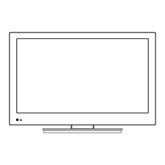
Page 4: Main Unit (Front View/Side View/Rear View)
Front Side buttons Remote control sensor Lights blue when your TV is on. Lights red when your TV is off (standby mode). When your TV is off, power Power indicator still flows into it. To disconnect all power, unplug the power cord. - Page 5 Back Connect a digital optical cable to this jack to output a digital audio signal to a digital audio amplifier. For DIGITAL OUTPUT more information, see “Connecting a digital sound system” on page 12. Connect an HDMI device, such as a cable box or DVD player, to this jack.
-
Page 6: Specifications
TV type TV panel 19-inch TFT LCD TV system NTSC-M, ATSC Channels VHF: 2 - 13 UHF: 14 - 69 CATV: 1 - 125 CADTV: 1-135 DTV: 2 - 69 Audio multiplex BTSC system Audio output 5W × 2 Power requirement AC 120 V, 60 Hz Power consumption 35 W... -
Page 7: Alignment Instructions
Alignment Instruction Alignment equipment VG848(YPbPr、VGA signal generator) VG849 ( HDMI signal generator) CA210(white balance apparatus) Alignment flow Test the voltage of power supply According to the wiring diagram “9219KK4401JL”, connect main board, FM board, power board, IR board and key board correctly, then turn on the main power supply and press the key “standby”. - Page 8 Alignment Instruction Alignment flow chart Check if having written FALSH Produce main board Assembling and alignment(check if the voltage is 120V) White balance alignment Connect to the central signal source, check if every function of TV (such as omitted channels, analog signals control ,etc.)is normal, check if output of earphone and speakers is normal.
- Page 9 Alignment Instruction Alignment instruction Unit adjustment According to wiring diagram “9219KK4401JL”, connect main board, FM board, power board, key board and IR board correctly, connect to AC120V power supply, then power on the set, check if display is normal. Factory menu using method a) First press key “INPUT”, then press number keys “2、5、8、0”...
- Page 10 Alignment Instruction of the 13th scale as (280、288);fix item “Green Offset”, adjust items “Red Offset、Blue Offset” to set chromaticity coordinates of the 4th scale as (280、288). Repeat adjust items “Red Gain、 Blue Gain” and “Red Offset、Blue Offset” until chromaticity coordinates of both gray scales are (280、288), the error of dark scale should be within ±8 and the error of bright scale should be within ±5;...
- Page 11 Alignment Instruction Auto white balance adjustment The set should be working for over 30 minutes before white balance adjustment so that it can be in a stable state. Connect CA210 to USB port of a compute with a data line, connect VG848 and TV to COM port or virtual COM port of a computer respectively (default connection is that VG848 to COM5 and TV to COM1;...
- Page 12 Alignment Instruction Table 2 YUV signal format horizontal vertical dot pulse definition frequency frequency frequency memo 720×480i@59.94/60 Hz 15.734 59.94/60 13.5 480i(59.94/60p) 720 × 480p@59.94/60 31.469 59.94/60 27.00 480p(59.94/60p) 1280 × 720p@59.94/60 44.96 59.94/60 74.18 720p(59.94/60p) 1920 × 1080i@59.94/60 33.75 59.94 74.25 1080i(59.94/60i)
- Page 13 Alignment Instruction HDMI port Input HDMI signal with format listed as Table2 respectively from VG849 signal generator, check if picture and sound are normal. FM port Connect to FM external antenna, enter into FM menu to auto-search channels, check if there is any omitted channel;...
-
Page 14: Software Upgrade Instructions
Software Upgrade Instruction The model can be upgraded from port of USB or RS232. Upgraded from USB is recommended for only a U disk is needed and upgrading speed is faster. Upgraded from RS232 can be used under the circumstances of failure to be upgraded from USB. Besides a computer and a serial line are needed, upgrading speed from RS232 is slower. - Page 15 Software Upgrade Instruction Fig.2 4. Power off the AC power supply, pull out the U disk, then power on the set again to complete the upgrading process. Upgraded from RS232 A computer and a serial line are needed. Online upgrading tool can be used with file“iDev.exe”...
- Page 16 Software Upgrade Instruction Fig. 3 1. Press button “setup” as Fig. 4; Fig. 4 Setup items “Serial Port” and “Baud Rate” correctly, select “Image Path” as Fig. 4 to load upgrading file “zTVApp_rom_aes.ecc”,select item “Update boot sector”, press button “OK”, then return to display a figure as Fig.
- Page 17 Software Upgrade Instruction 3. Press button “down” as Fig. 5; Fig. 5 A figure will be displayed as Fig. 6 if serial port has been occupied; Fig. 6 Now first close the software which is occupying serial port, then press button “down” again;...
- Page 18 Software Upgrade Instruction 4. Power off/on the set again, then begin upgrading process as Fig. 7; Fig. 7 5. It will take a few minutes to upgrade until a figure as Fig. 8 displayed; Fig. 8 6. Power off the AC power supply, then power on the set again to complete the upgrading process.
-
Page 19: Working Principle Analysis
TV channel The signal is inputted to TUNER and then to IF from RF. IF signal is inputted to main chip to be demodulated by NTSC , ATSC and BTSC sections respectively, all of demodulation are completed within main chip. HDMI,AV,SV,YPBPR and VGA signals are inputted to main chip directly without any outside switch and EEPROM. -
Page 20: Block Diagram
DDR SDRAM SPI FLASH K4T51163QG-HCF7 W25X32VSSIG-E POWER 15V、5V、3.3V、1.8V、1.1V 5.0VSTB。3.3VSTB。1.8VSTB ANOLOG Panel AUDIO INPUTS LVDS AUDIO FM Si4702 TUNER TD1136/FV AV 1 SPEAKER AV 2 ZR39775 SVIDEO 1 R2S15112PF SVIDEO 2 HP AMP BH3547F YPbPr 1 YPbPr 2 RS232 HP802 HP AMP Audio out BH3547F HDMI 1... -
Page 21: Wiring Diagram
LCD panel LVDS cable F M b o a r d X 6 0 4 3 p i n X 6 0 1 5 p i n X 5 0 1 4 0 p i n power board main board... -
Page 22: Schematic Diagram
N 1 0 3 S 0 M e m o r y I / F VCC3_3 N101 HYB18TC512160BF-2.5 S0_DQ15 S0_A13 N 1 0 3 S0_DQ15 S0_A13 S0_DQ14 S0_A12 S0_BA0 S0_DQ15 S0_DQ14 S0_A12 DQ15 S0_DQ13 S0_A11 S0_BA1 S0_DQ14 S0_DQ13 S0_A11 X102 DQ14 S0_DQ12 S0_A10... - Page 23 VCC3_3_STB N 1 0 3 H D M I 0 I / F 002:B2 HDMI1_RX2+ HDMI0_D2P 002:B2 HDMI1_RX2- HDMI0_D2N 002:B2 HDMI1_RX1+ HDMI0_D1P R239 002:B2 HDMI1_RX1- HDMI0_D1N 002:B2 HDMI1_RX0+ HDMI0_D0P 002:B2 HDMI1_RX0- HDMI0_D0N HDMI1_5V N208 002:B2 HDMI1_CLK+ VCC3_3_STB HDMI1_5V FDC6301N HDMI0_CLKP N205 002:B2 HDMI1_CLK-...
- Page 24 R358 C337 YPBPR1_Y 003:F5;003:H2 N 1 0 3 X305 S-AV-8421 L316 SGMI2012-1R8KT V i d e o I n I / F AV2_V 003:F5;003:H1 TX0 001:H4 R359 C348 220n 003:E1;003:F5 SV1_Y SVIDEO0Y YPBPR1_PB 003:H2 RX0 001:H4 C349 220n 003:E2 SV1_C SVIDEO0C HJK-3.5-401 C322...
- Page 25 R432 YPBPR1_R 004:H2 R418 N 1 0 3 X403 R401 X402 PC_R 004:H2 JY-3541L-01-030 AV2-8413 004:H1 AV2_L A u d i o I / F R433 C451 004:B1 AV2_R LINE_IN1_R C452 YPBPR1_L 004:H2 004:B1 AV2_L LINE_IN1_L R419 C453 PC_L 004:H2 003:B2 AV1_R LINE_IN2_R...
- Page 26 N 1 0 3 VCC_PANEL L V D S I / F N 1 0 3 AF24 LVDS_ECLK_P VCC1_8_STB LVDS_CE_P VCC3_3 VCC3_3_STB AE24 LVDS_ECLK_N C501 R532 LVDS_CE_N 100n L501 L504 R543 R546 STGB1608-121PT 845R_1% STGB1608-121PT AE19 LVDS_OCLK_P 1_8V_STB_CHECK 005:F2 LVDS_CO_P AF19 LVDS_OCLK_N LVDSVCRX_REXT...
- Page 27 N 1 0 3 VCC5_0 N603 VCC1_1 VCC3_3 R653 MP2307 C611 C618 P o w e r 100n VCC15_0 VCC3_3 CORE_VDD0 IO_VDD0 R623 CORE_VDD1 IO_VDD1 CORE_VDD2 IO_VDD2 CORE_VDD3 IO_VDD3 VCC5_0_STB VCC3_3_STB N605 N606 COMP VCC5_0 CORE_VDD4 IO_VDD4 AZ1084S-ADJ VCC3_3 R644 AZ1117-3.3 CORE_VDD5 IO_VDD5...
- Page 28 VCC3_3 VCC3_3 100p L40P_08W STBL2012-102 VCC3_3 100n VCC3_3 STBL2012-102 DOUT 4704_L 001:A2 LOUT 100n RST_4704 001:C2 STBL2012-102 001:A2 RFGND ROUT 4704_R I2C2_CLK_4704_802 001:D3 STBL2012-102 VCC3_3 S i 4 7 0 4 I2C2_DATA_4704_802 001:D3 001:A2 RST_4704 BC847AW STBL2012-102 STBL2012-102 4704_R 001:E2 STBL2012-102 4704_L 001:E2...
- Page 29 X503 T 5 0 2 R545 T - D D 2 L505 12V-1 LI050 BAV99 D515 V501 R546 BC847B R522 X504 N508 SI9936DY R543 N 5 0 7 O Z 9 9 3 8 D512 CD4148WP V502 2N7002-T1 D R V 1 P G N D C536 2.2u...
- Page 30 N505 D2SB60 D501 BA50BC0T C519 100p FU502 T 5 0 1 D523 3A/125V SR506 R563 E E R 2 8 L - 1 5VSTB N506 7.5V C529 KA278R05C C518 RT501 C506 Vadj LF1515 470p 0.1uF 1000u 5V-1 275VAC 500V C531 L501 R558 D505...
-
Page 31: Exploded View
LC-19KK44... -
Page 32: Exploded View Parts List
LC-19KK44 Part No. DISCRIPTION 6619440010 front cabinet assembly 5Z19440030 Middle cabinet 5203195201 Display panel 5810069020 Interface baffle(side) 5740232010 Main frame HIPS VO 5810068900 Interface baffle 6KK0030110 main board assembly 6KK0030910 IR board assembly 5H1944H020 back cabinet 6158109000 Rotor assembly 6151186020 Stand assembly... -
Page 33: 9219Kk4410 Replacement Parts List
9219KK4410 Replacement Parts List LOCA. NO. PART NO. DESCRIPTION C636 53703747 SMT ELE CAP. CDPS_10V_470uF_M 5203195201 PANEL _CLAA185WA02 ! 5213320004 CRYSTAL 32.768K G102 5216250005 CRYSTAL HC-49S 25MHZ LED901 5221200003 DIODE HFT503MPBR-1 D510 5225097002 DIODE HZ11A1 D503 5225156002 DIODE HZ16-1 D524 5225199002 DIODE HZ20-2 D501... - Page 34 9219KK4410 Replacement Parts List N103 5270775001 SMT IC SUPRAHD775 N310 5270802001 SMT IC HP802 N110 5270809002 SMT IC MAX809 STR N605 5271084001 SMT IC AZ1084S-ADJ N607 5271084001 SMT IC AZ1084S-ADJ N608 5271117002 SMT IC AS1117M-3.3 N606 5271117010 SMT IC AZ1117-3.3 N601 5271410002 SMT IC MP1410-C019...
- Page 35 9219KK4410 Replacement Parts List X404 5289000065 AV SOCKET_HJR-413/PB-1 X302 5289000073 AV SOCKET_AV13-05-501 X301 5289000096 AV SOCKET_HJR-613/PB-4 X304 5289000124 VGA SOCKET_HC1038-15F1-3.08 5291000001 SWITCH_KFC-A06-4X4.5X5B T502 5422063004 TRANSFORMER_BCQ-EEL19-XE T501 5422097004 TRANSFORMER_BK-35-01XB ! L501 5452000085 FILTER_UF2327M-163Y1R5-X02! L502 5452000093 LINE FILTER_LCL-1818D ! L404 5452000104 LINE FILTER_LCL4.5-2HA L405 5452000104 LINE FILTER_LCL4.5-2HA...
- Page 36 CONDUCTIVE WASHER_20X21X60 5870299010 CONDUCTIVE WASHER_20X21X60 5903027500 HANDLE 5932094000 HANDLE WASHER 5944034960 MANUAL_L19KK44_INSIGNIA (English) 5944034970 MANUAL_L19KK44_INSIGNIA (spanish) 5946006730 MANUAL_L19KK44_INSIGNIA (BBY) 5947534000 CAR LABEL_DX-LCD32-09 DYNEX 5947536400 TRANSPORTION LABEL_65X65 (BBY) 5947537717 PORT BAFFLE_LC-19KK44 5947553000 PORT BAFFLE_LC-19KK44 (side) 5947562700 LABEL (BBY) 5947562700 LABEL (BBY)
- Page 37 9219KK4410 Replacement Parts List 5947562700 LABEL (BBY) 5947563800 REMOTE LABEL_RC-X07-0B 5961219900 FOAM_EPE 5961220000 FOAM_EPE 5962004708 ACCESSORY BAG_220X355X0.03 5962019800 POLY BAG_90X280X0.04 5962107400 POLY BAG_100X230 5962113300 POLY BAG_840X470 5962116700 POLY BAG 5981130105 SCREW P(+) T3X10BT-D.Zn 5981130105 SCREW P(+) T3X10BT-D.Zn 5981330081 SCREW B(+) T3X8BT-D.Zn 5981330081 SCREW B(+) T3X8BT-D.Zn 5981330081...
- Page 38 9219KK4410 Replacement Parts List J518 5990000000 LIGHT WIRE J522 5990000000 LIGHT WIRE J523 5990000000 LIGHT WIRE J527 5990000000 LIGHT WIRE J528 5990000000 LIGHT WIRE J533 5990000000 LIGHT WIRE J540 5990000000 LIGHT WIRE_LC-19X44/DZ-5119 6151186020 STAND ASSY_LC-19X44 6156090720 STAND ASSY_LC-19X44 6158109000 ROTOR ASSY_LC-19X44 6619440020 FRONT CABINET ASSY_1M_N_J 6619440030...
- Page 39 9219KK4410 Replacement Parts List R113 53112000H0 SMT RESISTOR_0603_1/10W_0_X R114 53112000H0 SMT RESISTOR_0603_1/10W_0_X R115 53112000H0 SMT RESISTOR_0603_1/10W_0_X R116 53112000H0 SMT RESISTOR_0603_1/10W_0_X R125 53112000H0 SMT RESISTOR_0603_1/10W_0_X R134 53112000H0 SMT RESISTOR_0603_1/10W_0_X 53112000H0 SMT RESISTOR_0603_1/10W_0_X 53112000H0 SMT RESISTOR_0603_1/10W_0_X R201 53112000H0 SMT RESISTOR_0603_1/10W_0_X R202 53112000H0 SMT RESISTOR_0603_1/10W_0_X R203 53112000H0...
- Page 40 9219KK4410 Replacement Parts List R143 53112047H0 SMT RESISTOR_0603_1/10W_47_J R913 53112047H0 SMT RESISTOR_0603_1/10W_47_J R106 53112051H0 SMT RESISTOR_0603_1/10W_51_J R656 53112056H0 SMT RESISTOR_0603_1/10W_56_J R102 53112075F0 SMT RESISTOR_0603_1/10W_75_F R306 53112075H0 SMT RESISTOR_0603_1/10W_75_J R307 53112075H0 SMT RESISTOR_0603_1/10W_75_J R308 53112075H0 SMT RESISTOR_0603_1/10W_75_J R311 53112075H0 SMT RESISTOR_0603_1/10W_75_J R312 53112075H0 SMT RESISTOR_0603_1/10W_75_J...
- Page 41 9219KK4410 Replacement Parts List R543 53112137F1 SMT RESISTOR_0603_1/10W_374_F R544 53112137F1 SMT RESISTOR_0603_1/10W_374_F R234 53112139F0 SMT RESISTOR_0603_1/10W_390_F R546 53112147H0 SMT RESISTOR_0603_1/10W_470_J R547 53112147H0 SMT RESISTOR_0603_1/10W_470_J R636 53112149F1 SMT RESISTOR_0603_1/10W_499_F R914 53112151H0 SMT RESISTOR_0603_1/10W_510_J R504 53112182H0 SMT RESISTOR_0603_1/10W_820_J R534 53112210F0 SMT RESISTOR_0603_1/10W_1K_F R535 53112210F0 SMT RESISTOR_0603_1/10W_1K_F...
- Page 42 9219KK4410 Replacement Parts List R912 53112230H0 SMT RESISTOR_0603_1/10W_3K_J R513 53112233H0 SMT RESISTOR_0603_1/10W_3.3K_J R608 53112233H0 SMT RESISTOR_0603_1/10W_3.3K_J R330 53112239H0 SMT RESISTOR_0603_1/10W_3.9K_J R416 53112243H0 SMT RESISTOR_0603_1/10W_4.3K_J R902 53112243H0 SMT RESISTOR_0603_1/10W_4.3K_J R111 53112247H0 SMT RESISTOR_0603_1/10W_4.7K_J R117 53112247H0 SMT RESISTOR_0603_1/10W_4.7K_J R118 53112247H0 SMT RESISTOR_0603_1/10W_4.7K_J R120 53112247H0 SMT RESISTOR_0603_1/10W_4.7K_J...
- Page 43 9219KK4410 Replacement Parts List R616 53112247H0 SMT RESISTOR_0603_1/10W_4.7K_J R625 53112247H0 SMT RESISTOR_0603_1/10W_4.7K_J R631 53112247H0 SMT RESISTOR_0603_1/10W_4.7K_J R640 53112247H0 SMT RESISTOR_0603_1/10W_4.7K_J R641 53112247H0 SMT RESISTOR_0603_1/10W_4.7K_J R646 53112247H0 SMT RESISTOR_0603_1/10W_4.7K_J R649 53112247H0 SMT RESISTOR_0603_1/10W_4.7K_J R133 53112260F1 SMT RESISTOR_0603_1/10W_6.04K_F R624 53112268H0 SMT RESISTOR_0603_1/10W_6.8K_J R527 53112291H0 SMT RESISTOR_0603_1/10W_9.1K_J...
- Page 44 9219KK4410 Replacement Parts List R310 53112322H0 SMT RESISTOR_0603_1/10W_22K_J R314 53112322H0 SMT RESISTOR_0603_1/10W_22K_J R315 53112322H0 SMT RESISTOR_0603_1/10W_22K_J R401 53112322H0 SMT RESISTOR_0603_1/10W_22K_J R402 53112322H0 SMT RESISTOR_0603_1/10W_22K_J R403 53112322H0 SMT RESISTOR_0603_1/10W_22K_J R404 53112322H0 SMT RESISTOR_0603_1/10W_22K_J R418 53112322H0 SMT RESISTOR_0603_1/10W_22K_J R419 53112322H0 SMT RESISTOR_0603_1/10W_22K_J R420 53112322H0 SMT RESISTOR_0603_1/10W_22K_J...
- Page 45 9219KK4410 Replacement Parts List 53112410H0 SMT RESISTOR_0603_1/10W_100K_J 53112410H0 SMT RESISTOR_0603_1/10W_100K_J 53112427H0 SMT RESISTOR_0603_1/10W_270K_J R140 53112510H0 SMT RESISTOR_0603_1/10W_1M_J R528 53112510H0 SMT RESISTOR_0603_1/10W_1M_J L412 53122000H0 SMT RESISTOR_0805_1/8W_0_J L415 53122000H0 SMT RESISTOR_0805_1/8W_0_J R358 53122000H0 SMT RESISTOR_0805_1/8W_0_J R359 53122000H0 SMT RESISTOR_0805_1/8W_0_J R360 53122000H0 SMT RESISTOR_0805_1/8W_0_J R361 53122000H0 SMT RESISTOR_0805_1/8W_0_J...
- Page 46 9219KK4410 Replacement Parts List R538 53122510H0 SMT RESISTOR_0805_1/8W_1M_J R532 53122533H0 SMT RESISTOR_0805_1/8W_3.3M_J 53122610H0 SMT RESISTOR_0805_1/8W_10M_J R612 53131000H0 SMT RESISTOR_1206_1/4W_0_J R626 53131000H0 SMT RESISTOR_1206_1/4W_0_J R642 53131000H0 SMT RESISTOR_1206_1/4W_0_J C511 5320522K01 CAPACITOR_EP050B225K-B-B C519 5325110H90 CAPACITOR_CC_SL_500V_101J C518 5325147K00 CAPACITOR_CT_B_500V_471K C507 5328110K0Y CAPACITOR_CK45-B3DD101KYLR C515 5328210K00 CAPACITOR_CT_B_2KV_102K C547...
- Page 47 9219KK4410 Replacement Parts List C423 53311510K0 SMT CAPACITOR_0603_X5R_16V_105K C434 53311510K0 SMT CAPACITOR_0603_X5R_16V_105K C449 53311510K0 SMT CAPACITOR_0603_X5R_16V_105K C450 53311510K0 SMT CAPACITOR_0603_X5R_16V_105K C451 53311510K0 SMT CAPACITOR_0603_X5R_16V_105K C452 53311510K0 SMT CAPACITOR_0603_X5R_16V_105K C453 53311510K0 SMT CAPACITOR_0603_X5R_16V_105K C454 53311510K0 SMT CAPACITOR_0603_X5R_16V_105K C455 53311510K0 SMT CAPACITOR_0603_X5R_16V_105K C456 53311510K0 SMT CAPACITOR_0603_X5R_16V_105K...
- Page 48 9219KK4410 Replacement Parts List C475 53312210H0 SMT CAPACITOR_0603_CG_25V_102J C476 53312210H0 SMT CAPACITOR_0603_CG_25V_102J 53312210H0 SMT CAPACITOR_0603_CG_25V_102J 53312210H0 SMT CAPACITOR_0603_CG_25V_102J 53312210H0 SMT CAPACITOR_0603_CG_25V_102J C606 53312310R0 SMT CAPACITOR_0603_2E_25V_103Z C607 53312310R0 SMT CAPACITOR_0603_2E_25V_103Z C611 53312310R0 SMT CAPACITOR_0603_2E_25V_103Z 53312322K0 SMT CAPACITOR_0603_X7R_25V_223K 53312410K0 SMT CAPACITOR_0603_2R_25V_104K 53312410K0 SMT CAPACITOR_0603_2R_25V_104K C140 53312410K0...
- Page 49 9219KK4410 Replacement Parts List C349 53312422M0 SMT CAPACITOR_0603_2E_25V_224M C350 53312422M0 SMT CAPACITOR_0603_2E_25V_224M C351 53312422M0 SMT CAPACITOR_0603_2E_25V_224M C353 53312422M0 SMT CAPACITOR_0603_2E_25V_224M C354 53312422M0 SMT CAPACITOR_0603_2E_25V_224M C355 53312422M0 SMT CAPACITOR_0603_2E_25V_224M C356 53312422M0 SMT CAPACITOR_0603_2E_25V_224M C357 53312422M0 SMT CAPACITOR_0603_2E_25V_224M C359 53312422M0 SMT CAPACITOR_0603_2E_25V_224M C360 53312422M0 SMT CAPACITOR_0603_2E_25V_224M...
- Page 50 9219KK4410 Replacement Parts List C366 53313310K0 SMT CAPACITOR_0603_2R_50V_103K C516 53313310K0 SMT CAPACITOR_0603_2R_50V_103K C610 53313310K0 SMT CAPACITOR_0603_2R_50V_103K C537 53313339K0 SMT CAPACITOR_0603_2R_50V_393K C617 53313339K0 SMT CAPACITOR_0603_2R_50V_393K C619 53313339K0 SMT CAPACITOR_0603_2R_50V_393K C623 53313339K0 SMT CAPACITOR_0603_2R_50V_393K C634 53313382K0 SMT CAPACITOR_0603_2R_50V_823K C512 53321547R0 SMT CAPACITOR_0805_2E_16V_475Z C620 53321547R0 SMT CAPACITOR_0805_2E_16V_475Z...
- Page 51 9219KK4410 Replacement Parts List C511 533A1210K0 SMT CAPACITOR_0402_ X7R_16V_102K C515 533A1210K0 SMT CAPACITOR_0402_ X7R_16V_102K C519 533A1210K0 SMT CAPACITOR_0402_ X7R_16V_102K C520 533A1210K0 SMT CAPACITOR_0402_ X7R_16V_102K C648 533A1310K0 SMT CAPACITOR_0402_X7R_16V_103K C101 533A1410R0 SMT CAPACITOR_0402_2E_16V_104Z C102 533A1410R0 SMT CAPACITOR_0402_2E_16V_104Z C108 533A1410R0 SMT CAPACITOR_0402_2E_16V_104Z C109 533A1410R0 SMT CAPACITOR_0402_2E_16V_104Z...
- Page 52 9219KK4410 Replacement Parts List C647 533A1410R0 SMT CAPACITOR_0402_2E_16V_104Z C650 533A1410R0 SMT CAPACITOR_0402_2E_16V_104Z C651 533A1410R0 SMT CAPACITOR_0402_2E_16V_104Z C652 533A1410R0 SMT CAPACITOR_0402_2E_16V_104Z C653 533A1410R0 SMT CAPACITOR_0402_2E_16V_104Z C654 533A1410R0 SMT CAPACITOR_0402_2E_16V_104Z C655 533A1410R0 SMT CAPACITOR_0402_2E_16V_104Z C656 533A1410R0 SMT CAPACITOR_0402_2E_16V_104Z C657 533A1410R0 SMT CAPACITOR_0402_2E_16V_104Z C658 533A1410R0 SMT CAPACITOR_0402_2E_16V_104Z...
- Page 53 9219KK4410 Replacement Parts List C676 533AA510R0 SMT CAPACITOR_0402_2E_10V_105Z C677 533AA510R0 SMT CAPACITOR_0402_2E_10V_105Z C678 533AA510R0 SMT CAPACITOR_0402_2E_10V_105Z C679 533AA510R0 SMT CAPACITOR_0402_2E_10V_105Z C503 5342B422K0 CAPACITOR_250VAC_0.22uF_K C506 5342B422K0 CAPACITOR_250VAC_0.22uF_K C502 5342B433K0 CAPACITOR_275VAC_0.33uF_K ! C435 534B0447H1 CAPACITOR_CL21X_50V_474J C436 534B0447H1 CAPACITOR_CL21X_50V_474J C509 53607715M4 ELE CAPACITOR_KXW_400V_150uF_M(D18) C625 5366C722M1 ELE CAPACITOR_CD110_10V_220uF_M...
- Page 54 53B4005001 THERMISTER_5D2-14LC 56203E3050 WIRE (3 PIN) N109 568KK0001A SOFTWARE_MAIN CPU_ATSC_CPT185_Bes 569KK0301A MAIN PCB_LC-19KK44 569KK03050 BUTTON PCB_LC-19KK44 569KK03090 INFRARED SENSOR PCB_LC-19KK44 569KK0346A FM CONNECTION PCB_LC-19KK44 569KT05200 POWER PCB_LC-19KT46 570030101A LIGHT CONDUCTING COLUMN 572011201C POWER CORD CLASP SRP501 580B450110 HEAT SINK SRP502...
- Page 55 59A3100041 FLOSS FABRIC 59A3100041 FLOSS FABRIC 59A3100041 FLOSS FABRIC 59A5001300 WIRE FIXED BLADE_NS-L19X-10A,INSIGN 5A24634233 BACK NAME PLATE LABEL 5A31170010 FRONT NAME PLATE_INSIGNIA 19" 5A31170010 FRONT NAME PLATE_INSIGNIA 19" 5B02907001 PACKING BOX_NS-L19X-10A,INSIGNIA 5H1944H020 BACK CABINET_19_N_U 5Z19440030 MIDDLE CABINET 690HA00001 DUMMY ASSY...
-
Page 56: Printed Circuit Board
9219KK4410 Printed Circuit Board C438 L402 C427 X601 X604 R201 C433 C419 X406 C415 C612 R603 R611 569KK03010 V4 R512 R648 R616 X603 R647 20081201 C436 R619 5.6.35.36.37.38.39.40 GND C413 R551 1.2.3.4 VCC R422 N406 C417 C336 R217 R205 C414 X501 C428 N205... -
Page 57: Troubleshooting Guides
(1)Indicator light d oes not work after power-on Indicator light does not work after power-on Voltage of X602-11# is 5V ? Voltage of R644 is 3.3V ? Check out power board Voltage of X601-5# is 3.3V ? Check out N606 Yes No Check out IR board Check out main chip... - Page 58 (2)The set cannot work with key control or remote control and indicator light is keeping red after power-on . Fail to power on Check if voltage of X602-13# is low when standby ? Check if voltage of Check if voltage of R637 is low X602-11# drop less 4V at when standby ? the moment of power-on...
- Page 59 (3)No back light after power-on No back light after power-on Check if voltage of X602-1# is above 2.5V? Check out power board Check out main chip...
- Page 60 (4)No picture but has back-light after power-on No picture but has back-light after power-on Check if LVDS line is loose? Check if voltage of X501-1# is 5V ? Plug in LVDS line well Check out N601 Check if voltage of X602-2# is above 0.8V ? Check out peripheral circuits of PWM Check out main chip...
- Page 61 (5)Fail to search TV channels Fail to search TV channels Check if voltage of Tuner-4#/7# is 5V ? Check out 5V circuits from Check if I2C1 bus is normal ? power board to Tuner Check out peripheral Check if there is output from circuits of I2C1 bus Tuner-16#/17# ? Check out Tuner...
- Page 62 (6) Fail to search FM channels Fail to search FM channels Check if voltage of X406-1# is 3.3V ? Check if schedule bar is moving Check out N608 when searching channels ? Check if crystal of Check if I2C2 bus is FM module is working ? connected to X406-3#/4# ? Check out...
- Page 63 (7)No video signal in a certain channel No video signal in a certain channel Check if there is a signal inputted to external port ? Check if there is a signal Check out to input pin of main chip ? equipment Check out Check out circuits between...
- Page 64 (8)No audio signal in one channel No audio signal in one channel Check if there is a signal inputted to external port ? Check if there is a signal Check out equipment to input pin of main chip ? Check if there is a signal from Check out circuits between audio output pin of main chip ? external port and main chip...
- Page 65 (9)Abnormal functions of a channel auto-checkout Abnormal functions of a channel auto-checkout Check if I2C2 bus is connected to N310-26#/27# ? Check if there is a signal Check out peripheral from/to 35-40 pin of N310 ? circuits of I2C2 bus Check out peripheral Check out N310 circuits of signal port...
- Page 66 (10)Fail to upgrade from USB port Fail to upgrade from a USB port Check if the U disk is normal ? Check if voltage of Change a U disk X306-1# is 5V ? Check out peripheral Check if there is a circuits of 5V short between X306-2#/3# Check out main chip...
- Page 67 (11)No sound from earphone or Audio Out No sound from earphone or Audio Out Check if voltage of N405/N410-8# is 5V ? Check if there is a Check out peripheral signal to N405/N410-3#/5# ? circuits of 5V Check if voltage of Check out main chip N405/N410-2# is high ? Check out...
Need help?
Do you have a question about the 19KK44 and is the answer not in the manual?
Questions and answers