Table of Contents
Advertisement
Available languages
Available languages
Quick Links
rev.2 25/01/2021
INVERTER IRIS BLUE 2
SQ717.xx
MANUALE DI ISTRUZIONE E INSTALLAZIONE
INSTRUCTION AND INSTALLATION MANUAL
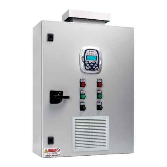
Quadro elettronico avviamento inverter 2 motori con display.
Inverter starting control panel 2 motors with display
CUSTOMER SERVICE
customer.service@salupoquadri.com
( )
+39 0 941.1820216
Advertisement
Table of Contents

Related Manuals for SALUPO IRIS BLUE 2


Summary of Contents for SALUPO IRIS BLUE 2
- Page 1 25/01/2021 INVERTER IRIS BLUE 2 SQ717.xx MANUALE DI ISTRUZIONE E INSTALLAZIONE INSTRUCTION AND INSTALLATION MANUAL Quadro elettronico avviamento inverter 2 motori con display. Inverter starting control panel 2 motors with display CUSTOMER SERVICE customer.service@salupoquadri.com +39 0 941.1820216...
-
Page 2: Table Of Contents
INDICE 1. Istruzioni generali per l’installazione 2. Avvertenze 3. Esempi applicativi 4. Schema di collegamento 5. Schema elettrico 6. Programmazione 6.1 Programmazione marcia a secco 7. Parametri di default 8. Esempio funzionale di un impianto idraulico semplice 9. Smaltimento di vecchi apparecchi elettrici ed elettronici 10. -
Page 3: Istruzioni Generali Per L'installazione
1. ISTRUZIONI GENERALI PER L’INSTALLAZIONE ITALIANO Assicurarsi che la linea sia protetta, secondo le normative, in funzione dell'applicazione. Accertarsi che la potenza e la corrente di targa del motore rispecchino i limiti di impiego del quadro. Installare il quadro in ambienti adatti al suo grado di protezione IP65. Per il fissaggio dell'involucro, utilizzare le staffe per i box 03-04 e le apposite predisposizioni per i restanti box. -
Page 4: Esempi Applicativi
3. ESEMPI APPLICATIVI Di seguito vengono illustrati alcuni esempi pratici delle applicazioni che è possibile realizzare con il quadro INVERTER IRIS BLUE 2. 4-20mA bar 4-20mA metri ANALOG ANALOG 4-20mA 4-20mA TRANSD. 4-20mA PIEZOR. G.MIN 4-20m A LEGENDA COMPONENTI Galleggiante per acque pulite... -
Page 5: Schema Di Collegamento
4. SCHEMA DI COLLEGAMENTO ITALIANO ALIMENTAZIONE 400 Vac ± 10 % 50 Hz TRASDUTTORE 4 -20 mA MOTORE 1 MOTORE 2 PRESSOSTATO O GALLEGGIANTE COLLEGAMENTO TRASDUTTORE DI PRESSIONE - BIANCO + MARRONE Max 10 mm² Max 10 mm² Max 6 mm² (M4) 1,4Nm 0,8Nm... -
Page 6: Schema Elettrico
5. SCHEMA ELETTRICO... - Page 7 5. SCHEMA ELETTRICO ITALIANO...
-
Page 8: Programmazione
6. PROGRAMMAZIONE ITALIANO Nella schermata seguente (fig. 1) è possibile visualizzare le diverse unità di misura con il seguente ordine: Frequenza motore (0.0Hz); Corrente assorbita (0.0A); Pressione impianto (0.00bar); Pressione di riferimento (3.00bar). Sul display è visibile la pressione di riferimento, impostata di default a 3.00 bar. - Page 9 6. PROGRAMMAZIONE ITALIANO Una volta che comparirà PRef (fig. 3) basterà cliccare la freccia ▲ o ▼ per aumentare o diminuire la pressione di riferimento. +0.0Hz 0.0A 0.00bar Pref 4.00bar (fig.3) Una volta impostata la pressione desiderata, bisognerà premere il tasto ENTER e il parametro verrà automaticamente memorizzato.
-
Page 10: Programmazione Marcia A Secco
6. PROGRAMMAZIONE ITALIANO Per modificare i parametri descritti in precedenza (C017 e C018), bisognerà cliccare il tasto “ENTER” e spostarsi con la freccia ▲ nella schermata dove compare scritto “C017…”, premere ENTER e con le frecce ▲ - ▼ impostare la potenza nominale del motore e infine cliccare nuovamente ENTER per memorizzare il parametro. -
Page 11: Parametri Di Default
7. PARAMETRI DI DEFAULT ITALIANO GESTIONE 3 SETPOINT DIFFERENTI DOVE E' P001 = engineering PREVISTO P265 = Keypad C188a = MDI4; P266d = bar C188b = MDI7; P266e = 0 C188c = MDI8; P266f = 10 bar P081a = ….bar (primo riferimento setpoint); P267 = bar P082a =…... -
Page 12: Esempio Funzionale Di Un Impianto Idraulico Semplice
8. ESEMPIO FUNZIONALE DI UN IMPIANTO IDRAULICO SEMPLICE Comando di 2 pompe in cascata ad attivazione e disattivazione con controllo PID di pressione. 380V... - Page 13 INDEX 1. General instructions for installing 2. Warnings 3. Application examples 4. Wiring diagram 5. Electrical diagram 6. Programming 6.1 Dry running programming 7. Default parameters 8. Functional exemple of a simple hydraulic system Disposal of electrical & electronic equipment Declaration of conformity 11.
- Page 14 1. GENERAL INSTRUCTIONS FOR INSTALLING ENGLISH Make sure power supply is protected up to standard depending on application. The power of the motor has to be within the control panel's limits of use. Install the control panel in an environment appropriate to its IP65 degree of protection. To fix the enclosure, use the brackets for the boxes 03-04 and the special predispositions for the remaining boxes.
- Page 15 3. APPLICATION EXAMPLES ENGLISH Below are some practical examples of applications that can be implemented with the INVERTER IRIS BLUE 2 control panel. 4-20mA bar 4-20mA meters ANALOG ANALOG 4-20mA 4-20mA TRANSD. 4-20mA PIEZOR. G.MIN 4-20m A COMPONENTS KEY Float switch for clean water...
- Page 16 3. WIRING DIAGRAM POWER SUPPLY 400 Vac ± 10 % 50 Hz TRANSDUCER 4 -20 mA MOTOR 1 MOTOR 2 PRESSURE SWITCH OR FLOAT SWITCH CONNECTION WITH PRESSURE TRANSDUCER - WHITE + BROWN Max 10 mm² Max 10 mm² Max 6 mm² (M4) 1,4Nm 0,8Nm...
- Page 17 4. ELECTRICAL DIAGRAM ENGLISH...
- Page 18 4. ELECTRICAL DIAGRAM...
- Page 19 5. PROGRAMMING ENGLISH In the following screen (fig.1) it’s possible to see the different unit of measure with the following order: Motor frequency (0.0Hz); Current consumption (0.0A); Plant pressure (0.00bar); Reference pressure (3.00bar). The reference pressure is visible on the display, set by default at 3.00 bar.
- Page 20 5. PROGRAMMING Once you see Pref (fig.3) just click on the arrow ▲or ▼ to increase or decrease the reference pressure. +0.0Hz 0.0A 0.00bar Pref 4.00bar (fig.3) Once the desidered pressure is set, you will need to press the ENTER key and the parameter will automatically be stored.
- Page 21 5. PROGRAMMING ENGLISH To modify the parameters described in precedence (C017 and C018), it will be necessary to click the "ENTER" key and move with the arrow ▲ in the screen where "C017 ..." appears, then press ENTER and set the rated motor power through the arrows ▲ -▼. Finally click ENTER again to store the parameter.
- Page 22 6. DEFAULT PARAMETERS 3 SETPOINT MANAGING (IF REQUIRED) P001 = engineering C188a = MDI4; P265 = Keypad C188b = MDI7; P266d = bar C188c = MDI8; P266e = 0 P081a = ….bar (primo riferimento setpoint); P266f = 10 bar P082a =… bar(secondo riferimento setpoint); P267 = bar P084a = …..bar (terzo riferimento setpoint) ;...
- Page 23 8. FUNCTIONAL EXEMPLE OF A SIMPLE HYDRAULIC SYSTEM ENGLISH Control of 2 pumps in cascade for activation and deactivation with PID pressure control. Power supply 380V Contactor KM1 (pump 2) Pressure probe Alternatively 4-20mA Direct starting- 0 ÷ P Max Star delta starting- Soft Starte/Stop starting Thermal relay...
-
Page 24: Smaltimento Di Vecchi Apparecchi Elettrici Ed Elettronici
98070 Torrenova (ME) Declares that: the INVERTER IRIS BLUE 2 control panels comply with the specific protection prerequisites concerning both safety (low voltage) and the electromagnetic compatibility provided for by the European Community laws 2006/95/CEE of 16th January 2007, 2004/108/CE of 10th November 2007, 93/68/CEE of 22th July 1993. -
Page 25: Certificato Di Garanzia
Dear customer, Salupo S.r.l. would like to thank you for your preference. The product you have purchased is covered by the warranty as shown below. We guarantee the quality and smooth operation of our products up to 24 months, starting from the date of purchase, against manufacturing defects and except for the following items for which we guarantee up to 12 months: SQ702.xx;... - Page 26 NOTE ________________________________________________ ________________________________________________ ________________________________________________ ________________________________________________ ________________________________________________ ________________________________________________ ________________________________________________ ________________________________________________ ________________________________________________ ________________________________________________ ________________________________________________ ________________________________________________ ________________________________________________ ________________________________________________ ________________________________________________ ________________________________________________ ________________________________________________ ________________________________________________...
- Page 27 NOTE ________________________________________________ ________________________________________________ ________________________________________________ ________________________________________________ ________________________________________________ ________________________________________________ ________________________________________________ ________________________________________________ ________________________________________________ ________________________________________________ ________________________________________________ ________________________________________________ ________________________________________________ ________________________________________________ ________________________________________________ ________________________________________________ ________________________________________________ ________________________________________________...
- Page 28 C/da Pietra di Roma Via Vicolo VI, n°2 98070 Torrenova (ME) ITALY Tel.:+39 - 0941 - 950216 Fax:+39 - 0941 - 958777 www.salupoquadri.com e-mail: info@salupoquadri.com...
Need help?
Do you have a question about the IRIS BLUE 2 and is the answer not in the manual?
Questions and answers