Table of Contents
Advertisement
Quick Links
Advertisement
Table of Contents

Related Manuals for Daewoo KOR-6185


Summary of Contents for Daewoo KOR-6185
- Page 1 Service Manual Microwave Oven Model: KOR-6185 DAEWOO ELECTRONICS CO., LTD.
-
Page 2: Table Of Contents
PRECAUTIONS TO BE OBSERVED BEFORE AND DURING SERVICING TO AVOID POSSIBLE EXPOSURE TO EXCESSIVE MICROWAVE ENERGY (a) Do not operate or allow the oven to be operated with the door open. (b) Make the following safety checks on all ovens to be serviced before activating the magnetron or other microwave source, and make repairs as necessary: (1) Interlock operation, (2) proper door closing, (3) seal and sealing surfaces (arcing, wear, and other damage), (4) damage to or loosening of hinges and latches, (5) evidence of dropping or abuse. -
Page 3: Proper Use And Service Precautions
CAUTION : This Device is to be Serviced Only by Porperly Qualified Service Personnel. Consult the Service Manual for Proper Service Procedures to Assure Continued Compliance with the Federal Performance Standard for Microwave Ovens and for Precautions to be Taken to Avoid Possible Exposure to Excessive Microwave Energy. -
Page 4: Specifications
SPECIFICATIONS ITEM SPECIFICATION POWER SUPPLY 120V~60HZ, SINGLE PHASE WITH EARTHING POWER CONSUMPTION 920W MICRO WAVE OUTPUT POWER 600W (IEC 705)(FULL MICROWAVE POWER) FREQUENCY 2450 MHz OUTSIDE DIMENSIONS (WXHXD) 465 X 274 X 364 mm CAVITY DIMENSIONS(WXHXD) 290 X 200 X 290 mm NET WEIGHT APPROX 12.5Kg TIMER... -
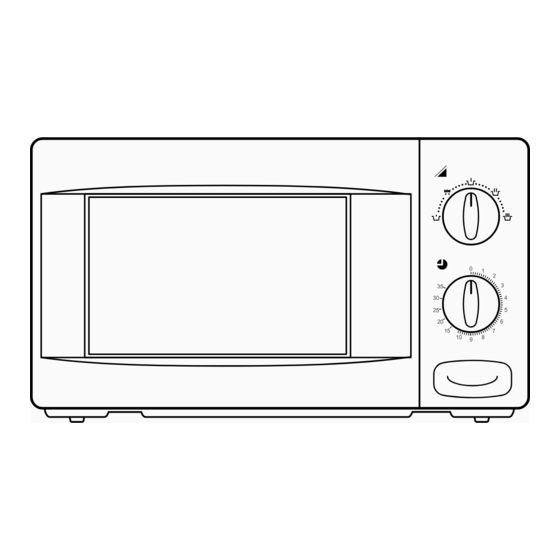
Page 5: Feature Diagram
FEATURES DIAGRAM 1 Saftey Interlock System. 2 Door Viewing Screen - Allows viewing of food, the screen is designed so that light can pass through, but not the microwave. 3 Door Hook - When the door is closed, it will automatically shut. If the door is opened while the oven is operating, the magnetron will immediately stop operating. -
Page 6: Installation
INSTALLATION Steady, flat location This microwave oven should be set on a steady, flat surface. Leave space behind and side All air vents should be kept a clearance. If all vents are covered during operation, the oven may overheat and, eventually, cause oven failure. -
Page 7: Operation
OPERATION Connect the main lead to an electrical outlet. After placing the food in a suitable container, open the oven door and put it on the glass tray. The glass tray must always be in place during cooking. CLOSE THE DOOR securely. Choose cooking power level by setting V.P.C. -
Page 8: Measurement Of The Microwave Output Power
MEASUREMENT OF THE MICROWAVE OUTPUT POWER Microwave output power can be checked by indirectly measuring the temperature rise of a certain amount of water exposed to the microwave as directed below. Procedure 1. Microwave power output measurement is made with the microwave oven supplied at rated voltage and operated at its maximum microwave power setting with a load of 1,000±5cc of potable water. -
Page 9: Microwave Radiation Test
MICROWAVE RADIATION TEST WARNING • Make sure to check the microwave leakage before and after repair or adjustment. • Always, start measuring of an unknown field to assure safety for operating personnel from microwave energy. • Do not place your hands into any suspected microwave radiation field unless the safe density level is known. •... -
Page 10: Wiring Diagram
KOR-6185 WIRING DIAGRAM... -
Page 11: Circuit Description
CIRCUIT DESCRIPTION 1. When the food is placed in the oven cavity and door is closed. • The contact of the interlock monitor switch open. • The contacts of the primary interlock switch and secondary interlock switch close. Primary Interlock Timer Switch Switch... - Page 12 HIGH VOLTAGE TRANSFORMER H.V. CAPACITOR MAGNETRON H.V. DIODE Fig.2 3. When the door is opened during cooking. • Primary interlock switch and secondary interlock switch open to cut off the primary voltage to the high voltage transformer to stop microwave oscillation. •...
-
Page 13: Precautions For Disassembly And Repair
PRECAUTIONS FOR DISASSEMBLY AND REPAIR – Cautions to be observed when trouble shooting. Unlike many other appliances, the microwave oven is a high-voltage, high-current equipment. It is completely safety during normal operation. However, carelessness in servicing the oven can result in an electric shock or possible danger from a short circuit. -
Page 14: Disassembly And Assembly
DISASSEMBLY AND ASSEMBLY 1. To remove cabinet. Remove three screws on cabinet back. 2. To remove door assembly. 1) Remove two screws 1 which secure the stopper hinge top. 2) Remove the stopper hinge top 2 and door assembly 3 from top plate of cavity. 3) Remove the stopper hinge top 2 from door assembly. - Page 15 (1) Remove the gasket door(A07) from door weld ass’y (A05) (2) Remove the barrier screen inner(A06) from door weld ass’y(A05). (3) Remove the hook spring(A09) and the hook(A08). (4) Remove the hinge stopper top ass’y(A04). (5) Remove the door frame(A01) from door weld ass’y(A05). (6) Remove the barrier screen outer(A02) and the supporter barrier screen outer(A03).
- Page 16 5. To remove control panel parts. (1) Remove the screw which secure the control panel push up two snap fits and draw forward the control panel assembly. (2) Remove the screw (B05) which secure the VPC coupler(B04). (3) Pull out the VPC coupler(B04), VPC knob(B01) and the flat spring (B03) from the control panel(B02). (4) Remove two screws(B08) which secure the timer ass’y(B07).
- Page 17 6. To remove high voltage capacitor. (1) Remove a screw 1 which secure the grounding ring terminal of the H.V. diode 2 and the capacitor holder 3. (2) Remove the H.V. diode 2 from the capacitor holder 3. (3) Reverse the above steps for reassembly. High voltage circuit wiring MAGNETRON H.V.
- Page 18 CAUTION : Never install the magnetron without the metallic gasket plate which is packed with each magnetron to prevent microwave leakage. Whenever repair work is carried out on magnetron, check the microwave leakage. It shall not exceed 4mW/cm for a fully assembled oven with door normally cosed. Magnetron antenna Metallic...
-
Page 19: Interlock Mechanism
INTERLOCK MECHANISM The door lock mechanism is a device which ahs been specially designed to completely eliminate microwave radiation when the door is opened during operation, and thus to perfectly prevent the danger resulting from the leakage of microwave. (1) Primary interlock switch When the door is closed, the hook locks the oven door. - Page 20 (2) Secondary interlock switchand interlock monitor switch When the door is closed, the hook pushes the push lever down ward, the push lever pressed the button of the monitor interlock switch to bring it under “off”, condition and presses the button of the secondary interlock switch to biring it under “on”, condition.
-
Page 21: Trouble Shooting Guide
TROUBLE SHOOTING GUIDE Trouble Door shut, timer set but no cooking takes place. Does the fan motor work when you shut the door and turn the timer? Does 15A fuse blow? Replace continuity Check continuity of continuity primary interlock switch, interlock monitor switch secondary interlock switch with door shuted. - Page 22 Does the fan motoro when you shut the door and turn the timer? Replace or repair Does the oven lamp lgith? oven lamp, Does the turntable turn? turntable motor. Replace Check continuity NO microwave continuity magnetorn of filament of oscillation. magnetron *Do not operate when you check this continuity.
-
Page 23: Component Test Porcedure
COMPONENT TEST PROCEDURE 1. High voltage is present at the high voltage terminal of the voltage transformer during any cooking cycle. 2. It is neither necessary nor advisable to attempt measurement of the high voltage. 3. Before touching any oven components or wiring, always unplug the oven from its power source and discharge the capacitor (see page 14). - Page 24 SAFETY INTERLOCK CONTINUITY TEST 6. Interlock switches • You can test continuity of safety interlocks and monitor switch by using switch tester or ohmmeter. • The switch operation is checked by zero/unlimited. the meter should indicate zero resistance. • The sequence of check is interlock monitor switch; primary and secondary interlock switched check. 1) In case of interlock monitor switch check Condition 1) Door is opened.
-
Page 25: Exploded And Parts List
EXPLODED AND PARTS LIST EXPLODED AND PARTS LIST 1. Door Assembly DOOR AS : 3511707940 DOOR AS : REF NO. PART NAME PART CODE DESCRIPTION Q’TY REMARKS 3512202030 KOR-61850A FRAME DOOR BARRIER-SCREEN *O 3517003050 ACRYL SUPPORTER BARR-S *O 3515304610 STOPPER HINGE *T AS 3515201500 KOR-6115OS DOOR WELD AS... - Page 26 2. Control Panel Ass’y C-PANEL AS : 3516717410 REF NO. PART NAME PART CODE DESCRIPTION Q’TY REMARKS KNOB VPC 3513403520 3516713620 KOR-61850A CONTROL-PANEL SPRING FLAT 3515101600 SUS 301 T0.5 COUPLER VPC KNOB 3517400500 SCREW TAPPING 7122401211 T2STRS 4X12 MFZN COUPLER TIMER 3517400400 TIMER 3518204300...
- Page 27 3. Main Unit KOR-6185...
- Page 28 KOR-6185 PARTS LIST REF NO. PART NAME PART CODE DESCRIPTION Q’TY REMARKS DOOR ASS’Y EXPLODED AND PART LIST CONTROL PANEL ASS’Y COVER WAVE GUIDE 3511403200 CAVITY AS 3516104800 KOR-611500S COUPLER 3517400600 GUIDE ROLLER AS 3512510600 KOR-61150S TRAY 3517203600 GLASS CABINET 3510801300 PCM T0.6...
Need help?
Do you have a question about the KOR-6185 and is the answer not in the manual?
Questions and answers