
Subscribe to Our Youtube Channel
Related Manuals for MX T406


Summary of Contents for MX T406
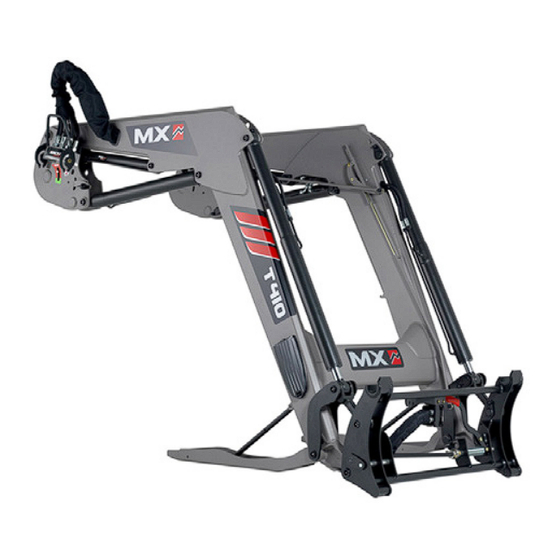
- Page 1 LOADER MX T406 / T406+ MX T408 / T408+ MX T410 / T410+ MX T412 / T412+ MX T414 MX T417 MX T418 User Manual Read carefully before using EN 366579 AK - 0622 Translation of the original manual...
- Page 3 We thank you for placing your trust in us and hope that you will find your MX loader satisfactory in every way. By taking a few minutes to read this manual, you will be able to obtain the best results from your MX loader to the full, prolong its service life and ensure safe operation.
-
Page 5: Table Of Contents
5.1 Control using the tractor's control valves 5.2 Control with the MX control valve 5.3 Control with MX PROPILOT control valve 5.4 Control with MX FLEXPILOT control valve 5.5 Control with MX e-PILOT S control valves 6. LOADER UNHITCHING 7. LOADER HITCHING 7.1 Two-step hitching 8. - Page 6 19.1 Extract from the Front Loaders standard EN12525 + A2 2010: 19.2 Use of the lifting and dumping safety device 20. MAINTENANCE 21. DIRECTIONS FOR USE 22. RECYCLING MX PRODUCTS 23. SAFETY LIFT RAM STOP ON LOADER 23.1 SAFETY STICKERS 24. TECHNICAL SPECIFICATIONS...
- Page 8 The loader is a complex machine. The operator must read this manual before using the loader for the first time. Familiarise yourself with: — The safety instructions. — Hitching and unhitching the loader. — Hitching and unhitching the implements. — Full use of the controls.
-
Page 9: Safety Rules
— For full use of the MX loader, the tractor must be fitted with a structure to protect against falling objects. If this is not the case, there are limits on the use of the MX loader (see the "LOADER USE LIMITS" section). CAUTION: the protective fitting must be in active position while working. -
Page 10: Ppe Table (Personal Protective Equipment)
If the tractor is not fitted with a structure protecting against falling loads, the driver is exposed to constant risk when handling loads. If the tractor is fitted with a roll cage only, the loader must be equipped with a parallelogram. Reminder: only implements recommended by the MX loader manufacturer may be used. Subject to modification... -
Page 11: Non-Compliance With Instructions For Safety And Use
MX on the MX loader, will render the MX guarantee on all supplied items null and void. — Use only genuine MX spare parts. Do not carry out any modifications yourself or have anyone else do so on your MX loader and its implements (mechanical, electrical, hydraulic or pneumatic specifications) without seeking prior approval in writing from MX. -
Page 12: Safety Stickers
2. Safety stickers Safety stickers are affixed to loaders. Ensure that these stickers are clean and legible; replace them if they become damaged. Symbol Meaning Familiarise yourself with the safety instructions in the user manual before using or working on the loader. -
Page 13: Identification Plate
3. Identification plate The identification plate is located inside the loader's right arm. The serial number and loader model shown on this plate must be quoted in any request for spare parts information or technical assistance. Subject to modification... -
Page 14: Counterweight
4. Counterweight The stability of the tractor-loader unit can only be ensured with a counterweight installed on the rear of the tractor. This should ensure that 20% of the gross weight (tractor, loader, implement, maximum load and counterweight) bears on the rear axle of the tractor for optimum working safety. -
Page 15: Control
Refer to the user manual for the tractor. 5.1.1 Front/rear control selector (optional) From the tractor's original joystick, the user in the cab controls either the MX loader or the rear couplings. Control with the MX control valve 5.2.1 Handle setting * To ensure comfortable control of the loader, the handle's position can be adjusted. - Page 16 5.3.1 Safety To prevent any accidental movement of the loader, the PROPILOT monolever can be locked. Move the unlocking lever (1). — (A): unlocked position. — (B): locked position. 5.3.2 Movements 1st function: along the “Y” axis — Forward = loader lowering (Double-action hydraulic ram operation).
-
Page 17: Control With Mx Flexpilot Control Valve
Control with MX FLEXPILOT control valve 5.4.1 Safety To prevent any accidental movement of the loader, the FLEXPILOT monolever can be locked. Turn the isolating thumbwheel (1): — (A): unlocked position. — (B): locked position. 5.4.2 Movements 1st function: along the “Y” axis —... -
Page 18: Control With Mx E-Pilot S Control Valves
— Button (1) + (4) + crowding or dumping movement. AUTO-LEVEL System Implement position reset. — Button (3). NOTE: Button (4) operational only with FAST-LOCK or SPEED- LINK 2. Control with MX e-PILOT S control valves See separate instructions for e-PILOT S. Subject to modification... -
Page 19: Loader Unhitching
6. Loader unhitching This operation must be carried out by the driver, who must exit the cab and ensure all manoeuvres are prohibited while working on the loader. Watch the unhitching/hitching video at www.m-x.eu The loader must always be connected to an implement of at least 100 kg in order to unhitch it. - Page 20 Setting the parking stands on first use 1. Position the implement flat on the ground. 2. Lower the parking stand. 3. Remove the rod stop (1) and position the parking stand on the ground. Subject to modification...
- Page 21 4. Select the notch (2) that gives a gap of between 3 and 5 cm to the ground when you manually raise the parking stand. 3...5 cm 5. In this position, lift the stop to meet the locking pin (3). 6.
- Page 22 — Hook the MACH System housing onto its support. — Disconnect the hydraulics and the electrics. Loader without MACH System: - Close the valve and disconnect the hydraulic couplings. - Fit the (clean) protective caps on the male and female couplings and stow the hoses on the loader.
- Page 23 — Reverse the tractor in one motion, then slowly until the loader is resting on its parking stands. — Check the stability of the whole assembly. Subject to modification...
-
Page 24: Loader Hitching
7. Loader hitching This operation must be carried out by the driver, who must exit the cab and ensure all manoeuvres are prohibited while working on the loader. Watch the unhitching/hitching video at www.m-x.eu — Check that the locking indicators on the left and right frames are in the red zone, and that no object is present to inhibit the loader connection. - Page 25 — Connect the hydraulics and the electrics. Loader with MACH System: - Ensure that the male and female couplings are clean before hitching. Clean them if necessary. - Take the housing in both hands and, with its back facing away, lift the control valve cover onto the guide bars and engage vertically.
-
Page 26: Two-Step Hitching
Two-step hitching 1. Connect the hydraulics and the electrics. 2. Move the lever forwards to the notched floating position + move the tractor forwards. If necessary, turn the wheels. 3. Gently activate lifting. The loader is locked (indicator shows green). Subject to modification... - Page 27 4. Raise and lock the right and left parking stands. 5. Check: apply ground force to the implement. Subject to modification...
-
Page 28: Implement Unhitching
8. Implement unhitching This operation must be carried out by the driver, who must exit the cab and ensure all manoeuvres are prohibited while working on the loader. Implement carrier with manual unlocking — Choose a level and solid surface. —... -
Page 29: Fast-Lock Implement Carrier
— Pull the lever towards you until it stays engaged. — Set the implement onto the ground, lightly dumping to release the implement carrier from the implement. FAST-LOCK implement carrier — Lift the loader to clear the implement from the ground. —... -
Page 30: Speed-Link 2 Implement Carrier
SPEED-LINK 2 implement carrier — Lift the loader to clear the implement from the ground. — Increase the operating life of the couplings by ensuring that the implement's hydraulic functions are not pressurized: for example, by slightly opening the grab. —... -
Page 31: Implement Hitching
9. Implement hitching This operation must be carried out by the driver, who must exit the cab and ensure all manoeuvres are prohibited while working on the loader. Implement carrier frame with manual locking — Ensure that the unlocking lever is in the hitching position (lever to the rear). -
Page 32: Fast-Lock Implement Carrier
— Ensure that the male and female couplings are clean before connection. Clean them if necessary. — Connect the hoses for implements with hydraulic functions. FAST-LOCK implement carrier — “Open” position, to allow space for the implement parts. — Align the loader with the implement, —... -
Page 33: Models Of Implement Carrier Frames
10.1 MX implement carrier frame 10.2 EURO implement carrier frame 10.3 MX/EURO implement carrier frame To switch from the MX position (1) to the Euro position (2), — Remove the pins, — Tilt the hitching shoes downwards, — Check that the hitching shoes are held in position by the spring rods, —... -
Page 34: Euro/Sms Implement Carrier Frame
— Tilt the two stops downwards. 10.5 MX/Faucheux-Blanc implement carrier frame To switch from MX position (1) to the Faucheux-Blanc position (2), — Remove the hitching shoes from their storage position, — Fit them in the hitching position and add the 4 fastening pins, —... -
Page 35: Mx/Euro/Tenias Implement Carrier Frame
10.7 MX/Euro/TENIAS implement carrier frame To switch from the TENIAS (1) position to the Euro (2) or MX (3) position, — Remove the pins, — Fit the shoes in the required position, — Refit the pins in their initial location. -
Page 36: Fast-Lock System
12. FAST-LOCK System The FAST-LOCK System (optional) on the implement carrier frame allows implements without hydraulic or electrical functions to be hitched and unhitched from the cab. Locked position (1). Unlocked position (2). Subject to modification... -
Page 37: Speed-Link 2 System
13. SPEED-LINK 2 System The SPEED-LINK 2 System (optional) on the implement carrier frame allows implements with hydraulic and electrical functions to be hitched and unhitched from the cab. SPEED-LINK 2 equipment (loader side) (1). SPEED-LINK 2 equipment (implement side) (2). A red/green indicator on the back of the SPEED-LINK 2 box indicates the locking status of the implement to the driver in the cab. -
Page 38: Pch System
14. PCH System The Hydraulic Compensation Parallelogram (PCH) operates automatically (optional). The system is fitted with hydraulic safety features to protect it from any malfunction. Two user positions of the PCH System are available. (1) “Bucket” position (2) “Pallet” position 14.1 “Bucket”... -
Page 39: Shock Eliminator System
15. SHOCK ELIMINATOR System Shocks are eliminated during movement or when stopping the loader suddenly when lowering (optional). This system softens impacts on the tractor and jolting in the cab. The Shock Eliminator can be isolated using the valve (1). NOTE: The Shock Eliminator can be activated or deactivated directly from the cab (electrical isolation option). -
Page 40: Bucket Operation Restrictor
16. Bucket operation restrictor The dumping restrictor (optional) is located at the end of the 3rd function solenoid valve, inside the right arm of the loader. 16.1 On/Off — ON: The restrictor is in operation and the bucket operates slowly. —... -
Page 41: Auto-Level System
17. AUTO-LEVEL System Automatic implement level reset, using the AUTO-LEVEL System (optional), is available for loaders controlled using the tractor's original control valve or by MX "Flexpilot" or "e-PILOT S" control valves. 17.1 Implement position adjustment The implement position is adjusted at the indicator rod. See pictures opposite. -
Page 42: Auto-Unload System
18. AUTO-UNLOAD System The bucket/grab synchronisation (optional) operates both ways: — Opening the grab/Tipping the bucket. — Crowding the bucket/Closing the grab. The AUTO-UNLOAD System only operates if the loader is fitted with a 3rd function. e-PILOT S control: see manual specific to e-PILOT S (function: AUTO-UNLOAD System). -
Page 43: Use Of The Lifting And Dumping Safety Device
— 300 mm, if the safety device is permanently activated. After 5 min, additional downward movement must not exceed 100 mm. " MX T400 19.2 Use of the lifting and dumping safety device The hydraulic circuit of the lifting and dumping rams is fitted with a safety device (1) and (2). -
Page 44: Maintenance
Button (4) is used exclusively to reactivate the safety device from outside the cab. In this case, the red indicator lights go off. 20. Maintenance Drain the tractor's hydraulic circuit regularly and change the filters in accordance with the manufacturer's recommendation. Contaminated oil ceases to lubricate, causing wear to all the hydraulic components (pumps, control valves, rams). - Page 45 Lubricate the MACH System locking system every 3 months. Lubricate every 10 hours and after each wash (water drives grease out), particularly after using a pressure washer. See the lubrication points opposite. Recommended type of grease for maintenance: NLGI 2 When using a pressure washer, do not direct the jet of water onto the electric components.
-
Page 46: Directions For Use
Tighten fasteners/screws in accordance with the tightening torque recommended in the table below. (Fasteners/screws used on the tractor must not be tightened using an air gun.) — Tightening torques (Nm) Thread Dowel Class of bolt marking (ISO 898) M 10 M 12 M 14 M 16... -
Page 47: Recycling Mx Products
22. Recycling MX products Hydraulic system — At the end of their service life, MX products must be drained of hydraulic oil by an authorised service technician. — The hydraulic hoses must be removed before the equipment can be recycled. -
Page 48: Safety Lift Ram Stop On Loader
23. SAFETY LIFT RAM STOP ON LOADER The lift ram stop must remain permanently attached to the loader. Install the lift ram safety stop before carrying out any work or maintenance operation under the raised loader arms. Failure to comply could result in death or serious injury. Only supplied in case of specific local safety regulations (Code of Practice, …). -
Page 49: Technical Specifications
Compliance plate. WARNING Do not exceed Rated Operating Load (ROL). TO AVOID SERIOUS INJURY OR DEATH CAUSED BY FALLING LOADS: • Load on raised bucket or fork can fall or roll back onto oprator causing serious injury or death. • Use approved clamping and/or guard attachments for handling large, loose or shiftable loads such as bales. - Page 50 T417/ T406 T406+ T408 T408+ T410 T410+ T412 T412+ T414 T418 2.30 m 2.30 m 2.40 m 2.40 m 2.50 m 2.50 m 2.60 m 2.60 m 2.75 m 2.75 m Length (A) 1.18 m 1.18 m 1.18 m 1.18 m 1.18 m...
- Page 51 Registered with the RCS of Rennes under number 639 200 260. Hereby declares that the material : Front loader T406 or T408 or T408+ or T410 or T410+ or T412 or T412+ or T414 or T417 or T418 or TX420 or TX425 or TX430...
- Page 56 M-extend France SAS 19, rue de Rennes B.P. 83221 FR-35690 ACIGNÉ Email : contact@m-x.eu Web : www.m-x.eu...
Need help?
Do you have a question about the T406 and is the answer not in the manual?
Questions and answers