
Subscribe to Our Youtube Channel
Related Manuals for MX A104


Summary of Contents for MX A104
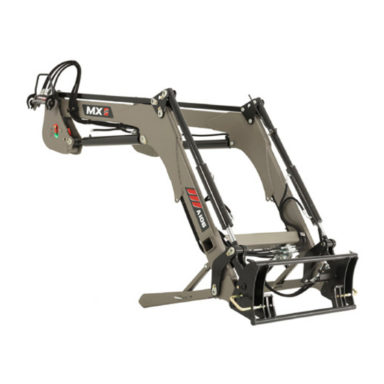
- Page 1 LOADER MX A104 MX A106 MX A110 User Manual Read carefully before using EN 369938 AD - 1022 Translation of the original manual...
- Page 3 We thank you for placing your trust in us and hope that you will find your MX loader satisfactory in every way. By taking a few minutes to read this manual, you will be able to obtain the best results from your MX loader to the full, prolong its service life and ensure safe operation.
-
Page 5: Table Of Contents
5.1 Control using the tractor's control valves 5.2 Control with the MX control valve 5.3 Control with MX PROPILOT control valve 5.4 Control with MX FLEXPILOT control valve 5.5 Control with MX e-PILOT S control valves 6. LOADER UNHITCHING 7. LOADER HITCHING 7.1 Two-step hitching 8. - Page 7 The loader is a complex machine. The operator must read this manual before using the loader for the first time. Familiarise yourself with: — The safety instructions. — Hitching and unhitching the loader. — Hitching and unhitching the implements. — Full use of the controls.
-
Page 8: Safety Rules
— For full use of the MX loader, the tractor must be fitted with a structure to protect against falling objects. If this is not the case, there are limits on the use of the MX loader (see the "LOADER USE LIMITS" section). CAUTION: the protective fitting must be in active position while working. -
Page 9: Ppe Table (Personal Protective Equipment)
If the tractor is not fitted with a structure protecting against falling loads, the driver is exposed to constant risk when handling loads. If the tractor is fitted with a roll cage only, the loader must be equipped with a parallelogram. Reminder: only implements recommended by the MX loader manufacturer may be used. Subject to modification... -
Page 10: Non-Compliance With Instructions For Safety And Use
MX on the MX loader, will render the MX guarantee on all supplied items null and void. — Use only genuine MX spare parts. Do not carry out any modifications yourself or have anyone else do so on your MX loader and its implements (mechanical, electrical, hydraulic or pneumatic specifications) without seeking prior approval in writing from MX. -
Page 11: Safety Stickers
2. Safety stickers Safety stickers are affixed to loaders. Ensure that these stickers are clean and legible; replace them if they become damaged. Symbol Meaning Familiarise yourself with the safety instructions in the user manual before using or working on the loader. -
Page 12: Identification Plate
3. Identification plate The identification plate is located inside the loader's right arm. The serial number and loader model shown on this plate must be quoted in any request for spare parts information or technical assistance. Subject to modification... -
Page 13: Counterweight
4. Counterweight The stability of the tractor-loader unit can only be ensured with a counterweight installed on the rear of the tractor. This should ensure that 20% of the gross weight (tractor, loader, implement, maximum load and counterweight) bears on the rear axle of the tractor for optimum working safety. -
Page 14: Control
Refer to the user manual for the tractor. 5.1.1 Front/rear control selector (optional) From the tractor's original joystick, the user in the cab controls either the MX loader or the rear couplings. Control with the MX control valve 5.2.1 Handle setting * To ensure comfortable control of the loader, the handle's position can be adjusted. - Page 15 5.3.1 Safety To prevent any accidental movement of the loader, the PROPILOT monolever can be locked. Move the unlocking lever (1). — (A): unlocked position. — (B): locked position. 5.3.2 Movements 1st function: along the “Y” axis — Forward = loader lowering (Double-action hydraulic ram operation).
-
Page 16: Control With Mx Flexpilot Control Valve
3rd Function: along "X" axis — Button (1) + crowding or dumping movement. NOTE: Buttons (2) and (3) not used. Control with MX FLEXPILOT control valve 5.4.1 Safety To prevent any accidental movement of the loader, the FLEXPILOT monolever can be locked. -
Page 17: Control With Mx E-Pilot S Control Valves
— To the right = implement dumping. 3rd Function: along "X" axis — Button (1) + crowding or dumping movement. NOTE: Buttons (2) and (3) not used. Control with MX e-PILOT S control valves See separate instructions for e-PILOT S. Subject to modification... -
Page 18: Loader Unhitching
6. Loader unhitching This operation must be carried out by the driver, who must exit the cab and ensure all manoeuvres are prohibited while working on the loader. Watch the unhitching/hitching video at www.m-x.eu The loader must always be connected to an implement of at least 100 kg in order to unhitch it. - Page 19 — There must be 10 to 30 mm between the ground and the base of the parking stand. 10...30 mm — On the right side, pull the unlocking handle downwards. IMPORTANT: The locking indicator is in the red zone. — Disconnect the hydraulics and the electrics. Loader with MACH System: - Unlock the housing of the MACH System by pressing the safety latch on the left, then lift the handle.
- Page 20 — Hook the MACH System housing onto its support. — Disconnect the hydraulics and the electrics. Loader without MACH System: - Close the valve and disconnect the hydraulic couplings. - Fit the (clean) protective caps on the male and female couplings and stow the hoses on the loader.
-
Page 21: Loader Hitching
— Check the stability of the whole assembly. 7. Loader hitching This operation must be carried out by the driver, who must exit the cab and ensure all manoeuvres are prohibited while working on the loader. Watch the unhitching/hitching video at www.m-x.eu —... - Page 22 — Connect the hydraulics and the electrics. Loader with MACH System: - Ensure that the male and female couplings are clean before hitching. Clean them if necessary. - Take the housing in both hands and, with its back facing away, lift the control valve cover onto the guide bars and engage vertically.
-
Page 23: Two-Step Hitching
Two-step hitching 1. Connect the hydraulics and the electrics. 2. Move the lever forwards to the notched floating position + move the tractor forwards. If necessary, turn the wheels. 3. Gently activate lifting. The loader is locked (indicator shows green). Subject to modification... - Page 24 4. Raise and lock the right and left parking stands. 5. Check: apply ground force to the implement. Subject to modification...
-
Page 25: Implement Unhitching
8. Implement unhitching This operation must be carried out by the driver, who must exit the cab and ensure all manoeuvres are prohibited while working on the loader. Implement carrier with manual unlocking — Choose a level and solid surface. —... - Page 26 — Unlocking the implement. — Stand to the left of the loader, NEVER IN FRONT, pull the locking handle towards you following (1) then (2). — Do the same on the right-hand side. — Unlocked implement position. — Set the implement onto the ground, lightly dumping to release the implement carrier from the implement.
-
Page 27: Implement Hitching
9. Implement hitching This operation must be carried out by the driver, who must exit the cab and ensure all manoeuvres are prohibited while working on the loader. Implement carrier frame with manual locking — Ensure that the unlocking lever is in the hitching position (lever to the rear). - Page 28 — Ensure that the male and female couplings are clean before connection. Clean them if necessary. — Connect the hoses for implements with hydraulic functions. CAUTION: Checks to be carried out before moving: Press the implement down on the ground (the tractor's front wheels lift) to check correct locking.
-
Page 29: Models Of Implement Carrier Frames
10. Models of implement carrier frames 10.1 MX implement carrier frame 10.2 EURO implement carrier frame Subject to modification... -
Page 30: Level Indicator
11. Level indicator The level indicator enables implement positioning as the loader is descending. It is located on the left side of the loader. It can be adjusted to suit the implement being used. (1) indicator (2) Bucket parallel to the ground Subject to modification... -
Page 31: Shock Eliminator System
12. SHOCK ELIMINATOR System Shocks are eliminated during movement or when stopping the loader suddenly when lowering (optional). This system softens impacts on the tractor and jolting in the cab. The Shock Eliminator can be isolated using the valve (1). NOTE: The Shock Eliminator can be activated or deactivated directly from the cab (electrical isolation option). -
Page 32: Safety When Lifting And Dumping
13. Safety when lifting and dumping In compliance with standard EN 12525 + A2 2010, it can be disengaged for working when no one is near the load. The movements can then be carried out, with no loss of power or speed of execution. Uniquely, this equipment is compatible with the Shock Eliminator and the notched floating position. -
Page 33: Maintenance
14. Maintenance Drain the tractor's hydraulic circuit regularly and change the filters in accordance with the manufacturer's recommendation. Contaminated oil ceases to lubricate, causing wear to all the hydraulic components (pumps, control valves, rams). Even clear oil may be spent. Maintenance operations must be performed by competent persons, authorised by the dealer. - Page 34 Lubricate every 10 hours and after each wash (water drives grease out), particularly after using a pressure washer. See the lubrication points opposite. Recommended type of grease for maintenance: NLGI 2 When using a pressure washer, do not direct the jet of water onto the electric components.
-
Page 35: Directions For Use
15. Directions for use — Each implement has been designed for a specific use and has its own resistance limits. — Land clearing and stump pulling are prohibited. This work must be done with specialized machinery and is not appropriate for the agricultural loader. -
Page 36: Safety Lift Ram Stop On Loader
16. SAFETY LIFT RAM STOP ON LOADER The lift ram stop must remain permanently attached to the loader. Install the lift ram safety stop before carrying out any work or maintenance operation under the raised loader arms. Failure to comply could result in death or serious injury. Only supplied in case of specific local safety regulations (Code of Practice, …). -
Page 37: Recycling Mx Products
17. Recycling MX products Hydraulic system — At the end of their service life, MX products must be drained of hydraulic oil by an authorised service technician. — The hydraulic hoses must be removed before the equipment can be recycled. -
Page 38: Technical Specifications
Recycling of decontaminated MX products — Decontaminated MX products will be sent to approved iron and metal recycling channels. 18. Technical specifications Subject to modification... - Page 39 A104 A106 A110 Length (A) 2.35 m 2.60 m 2.85 m Width (B) 1.17 m 1.17 m 1.17 m Height (C) 1.75 m 1.80 m 2.05 m Min. weight (with no option) 430 Kg 440 Kg 500 Kg Max. weight...
- Page 40 Front loader U403 or U404 or U405 or U406 or U406+ or U407 or U408 or U408+ or U409 or U410 or U410+ or U412 or U412+ or U414 Front loader A104 or A106 or A110 or F303 or F304 Front loader C1 or C1s or C2u or C2 or C2+ or C3u or C3 or C3+ or C4 or C4+...
- Page 44 M-extend France SAS 19, rue de Rennes B.P. 83221 FR-35690 ACIGNÉ Email : contact@m-x.eu Web : www.m-x.eu...
Need help?
Do you have a question about the A104 and is the answer not in the manual?
Questions and answers