Table of Contents
Advertisement
Quick Links
TECHNICAL MANUAL
Model DCEM2000
Dust Monitor
(with Ball Valve)
CODEL International Ltd.
Station Building, Station Road, Bakewell, Derbyshire DE45 1GE United Kingdom
t : +44 (0) 1629 814 351
f : +44 (0) 8700 566 307
e : codel@codel.co.uk
web : www.codel.co.uk
OPS.086
Issue : B
Rev. : 1
Date : 11/8/10
Doc. i/d : 0086/6
Ref. : 080047
Advertisement
Table of Contents

Related Manuals for CODEL DCEM2000


Summary of Contents for CODEL DCEM2000
- Page 1 TECHNICAL MANUAL Model DCEM2000 Dust Monitor (with Ball Valve) CODEL International Ltd. Station Building, Station Road, Bakewell, Derbyshire DE45 1GE United Kingdom t : +44 (0) 1629 814 351 f : +44 (0) 8700 566 307 e : codel@codel.co.uk web : www.codel.co.uk OPS.086...
- Page 2 CODEL OPS.086 Issue : B Rev. : 1 Date : 11/8/10 Doc. i/d : 0086/6 Ref. : 080047...
- Page 3 CODEL CODEL International Ltd is a UK company based in the heart of the Peak District National Park at High priority is placed upon customer support. Bakewell, Derbyshire. The company specialises CODEL’s dedicated team of field and service in the design and manufacture of high-technology...
- Page 4 CODEL OPS.086 Issue : B Rev. : 1 Date : 11/8/10 Doc. i/d : 0086/6 Ref. : 080047...
-
Page 5: Table Of Contents
1.1. Foreword 1.2. DCEM2000 Basic Principles 1.3. User Interface 1.4. Analogue and Logic Outputs 1.5. CDC Serial Port - for use with the CODEL IEM system 2. Overview of the CODEL Model DCEM2000 Dust Monitor 2.1. Introduction 2.2. Transceiver Units 2.3. - Page 7 CODEL Technical Manual OPS.086 Issue : B Rev. : 1 Date : 11/8/10 Doc. i/d : 0086/6 Ref. : 080047...
- Page 8 CODEL Technical Manual Important The warning signs (and meanings) shown below, are used throughout these instructions and are intended to ensure your safety while carrying out installation, operation and maintenance procedures. Please read these instructions fully before proceeding. Caution, risk of electric shock.
- Page 9 CODEL Technical Manual OPS.086 Issue : B Rev. : 1 Date : 11/8/10 Doc. i/d : 0086/6 Ref. : 080047...
-
Page 11: Codel Dcem2000 Analyser - Introduction
Data from up to 32 SmartCEM stations is transmitted via a serial digital link (CODEL SmartBUS) to the Central Datapoint where it is logged on a dedicated PC or assembled for onward transmission to a plant computer or DCS. -
Page 12: Dcem2000 Basic Principles
1.5 CDC Serial Port - for use with the CODEL IEM system The CDC is equipped with a 2-way serial communications port for use with the CODEL Integrated Emissions Monitoring (IEM) system. On plant where more than one CODEL analyser is installed, this is the preferred method and, even for a single analyser installation, can provide significant benefits. -
Page 13: Overview Of The Codel Model Dcem2000 Dust Monitor
Instruments in the past have, however, generally proved to be unreliable, falling rapidly into disuse or to be so expensive and complex as to be affordable only by the very large users, such as power stations. The CODEL DCEM2000 seeks to overcome these problems by providing a reliable, simple to use instrument with low maintenance requirements. -
Page 14: Station Control Unit (Scu)
CODEL Technical Manual Page 4 2.4 Station Control Unit (SCU) The SCU provides 48V DC power for the analysers on its local data bus. The 48V DC power input to the SCU is from a separate power supply fed from 86 to 264V AC maximum. -
Page 15: Measurement Principle
CODEL Technical Manual Page 5 3 Measurement Principle Consider the two identical transceivers positioned at either side of the flue (or duct), unit 1 and unit 2. The transmissivity of light from unit 1 to unit 2 (unit 1 transmitting) can be represented by the equation : τ... -
Page 16: Window Compensation
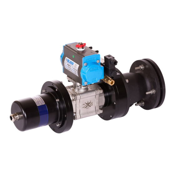
CODEL Technical Manual Page 6 As the two bracketed terms above are each measured from only one of the transceivers, the output of the instrument is independent of drift of either detector. 3.1 Window Compensation A reflector is mounted on the ‘ball’ of a compressed-air operated ball valve enabling it to be rotated in to and out of the optical path (see Figure 4). - Page 17 CODEL Technical Manual Page 7 and therefore, cτ – Dt mirror thus the transmissivity ‘τ’ at the lens can be determined as: τ Kcal and lens contamination is simply 1-τ OPS.086 Issue : B Rev. : 1 Date : 11/8/10 Doc.
-
Page 18: Specification
CODEL Technical Manual Page 8 4 Specification Response Time selectable from 10-seconds Maximum Path Length 0.5 – 15m Serial Data Port to communicate with a central processor as part of an integrated monitoring system. Dust Calibration By independent analysis (by others) * see below ±0.2% Opacity... -
Page 19: Installation
The analysers are supplied with standard 10m cables already connected. If any items are missing please inform CODEL or your local CODEL supplier immediately. The installation site should be free of all encumbrances and safety procedures should be observed at all times. -
Page 20: Air Purges
CODEL Technical Manual Page 10 Construct the mounting assemblies by welding each site mounting flange to a suitable stub-pipe, nominal bore 75mm. The pipe should be long enough to keep the equipment clear of any duct lagging and it also helps to insulate the equipment from high duct temperatures. -
Page 21: Ball Valves
CODEL Technical Manual Page 11 Figure 6 : Adjustable Mount Details 5.3.2 Ball Valves The ball valves are mounted to the air purges using four M6 hexagon head screws. Note that these screws locate through the nylon insulating bushes in the air purge flange and screw into the valve flange. The nylon isolation bushes are essential to maintain electrical isolation of the transceivers from the duct. -
Page 22: Signal Processor Unit
CODEL Technical Manual Page 12 5.3.4 Signal Processor Unit To mount the signal processor, first remove the cover by loosening the four captive screws. The case is then secured to a firm support by use of the four mounting holes, one in each corner of the case, outside the sealing rim. -
Page 23: Electrical Connections
The connection schedule for the DCEM2000 and Signal Processor Unit is shown in the following drawings. Important Note : The SCU may be integral with the GCU of an accompanying G-CEM4000 gas analyser. If no CODEL gas analyser has been supplied the DCEM2000 will have been provided with a separate SCU and PSU. These units should be installed and connected in accordance with the installation manuals that accompany them;... - Page 24 CODEL Technical Manual Page 14 Figure 9 : Connection Schedule OPS.086 Issue : B Rev. : 1 Date : 11/8/10 Doc. i/d : 0086/6 Ref. : 080047...
- Page 25 CODEL Technical Manual Page 15 Figure 10 : Detail of SPU Wiring OPS.086 Issue : B Rev. : 1 Date : 11/8/10 Doc. i/d : 0086/6 Ref. : 080047...
-
Page 26: Commissioning
Having installed the DCEM2000 in accordance with the installation manual, ensure that purge air is flowing to the purge units at a pressure of 1.5bar. Check that the address in the DCEM2000 control unit is set to 2. The two transceivers should be in approximate alignment before undertaking any further work involving the SmartCOM software. - Page 27 CODEL Technical Manual Page 17 Select an Auto update rate of 2 seconds and click on start. Yellow numbers on a background should appear. If a sky blue background appears click on Stop and begin again. If after 3 tries there is no black background check comms between the PC and SCU.
-
Page 28: Detector Levels
CODEL Technical Manual Page 18 7.3.2 Detector levels Select Detector levels in the Function box. The following screen should appear. Set Auto Update to 2 seconds and click on start. Next check the detector levels; the optimal values are: 20,000 ±2000 (Dr1 & Dr2) and 15,500 ±500 (Dt1 & Dt2). -
Page 29: Zero And Span Calibration
CODEL Technical Manual Page 19 7.3.3 Zero and span calibration Remember - the calibration routine must be run during commissioning, otherwise the instrument will not be able to calculate the true level within the duct. DO NOT run the calibration routine unless reasonable conditions exist in the duct. - Page 30 CODEL Technical Manual Page 20 Next select "Calibrate" in the selector box and the following screen will appear. If you want a full Check, that is a Zero and span calibration and window check, click on the target check box. If a window check or span check only is required click on the appropriate check box.
-
Page 31: Transmissivities
CODEL Technical Manual Page 21 Ensure that if the ‘Total % contamination’ is greater than 2% then the windows should be cleaned. The span check value should be within 1% of the target span value, if not, repeat the span check procedure using a larger number of target cal cycles. - Page 32 CODEL Technical Manual Page 22 Select 4 seconds in the ‘Auto update’ box and click on ‘start’. The opacity data should be divided by 100 and the extinction data by 10,000. OPS.086 Issue : B Rev. : 1 Date : 11/8/10 Doc.
-
Page 33: Routine Maintenance
Page 23 8 Routine Maintenance All CODEL equipment is designed for continuous and reliable operation and to keep the levels of maintenance to an absolute minimum. The electronics require no routine maintenance; they are all solid-state and undergo a rigorous factory burn-in procedure. -
Page 34: Fault Finding
In the absence of any CODEL trained technicians on site, it is strongly recommended that, in the event of a fault, CODEL or its local service agent be contacted immediately with equivalent current information contained in the analyser records. -
Page 35: Table Of Figures
Page 25 10 Table of Figures Figure 1 : Typical SmartCEM System Arrangement Figure 2 : Arrangement of DCEM2000 Figure 2 : Schematic of Principle of Transmissivity Figure 3 : Optical Arrangement of the D-CEM2100 Figure 5 : Stub Pipe Arrangement...
Need help?
Do you have a question about the DCEM2000 and is the answer not in the manual?
Questions and answers