LG LSE3090ST Service Manual
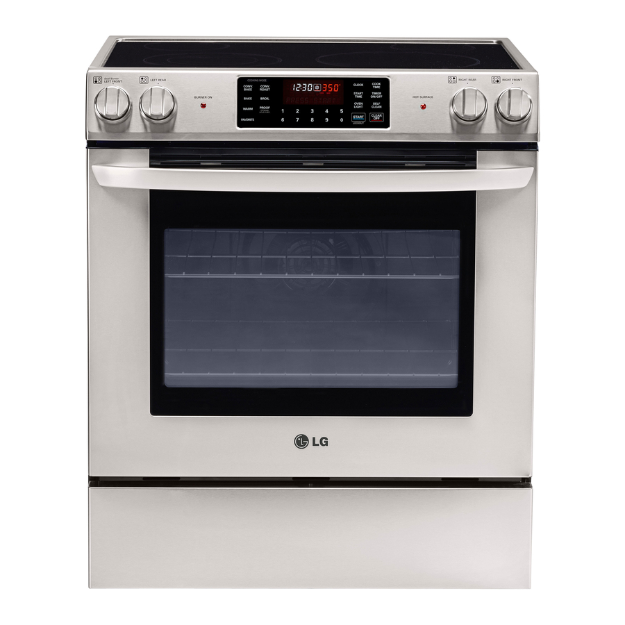
30” freestanding electric range
Hide thumbs
Also See for LSE3090ST:
- Owner's manual (93 pages) ,
- Installation manual (32 pages) ,
- Owner's manual (92 pages)
Table of Contents
Advertisement
Quick Links
Advertisement
Table of Contents

Related Manuals for LG LSE3090ST


Summary of Contents for LG LSE3090ST
- Page 1 삼 흥 정 판 Internal Use Only Website http://biz.lgservice.com 30” Freestanding Electric Range SERVICE MANUAL MODEL: LSE3090ST CAUTION BEFORE SERVICING THE UNIT, READ THE SAFETY PRECAUTIONS IN THIS MANUAL. April, 2014 P/NO : MFL62114804 Printed in Korea...
- Page 2 SAFETY PRECAUTIONS • Repairs of the appliance should be carried out by a licensed technician only. Incorrect repairs may result in dangerous situations. If you need repairs, contact an LG Service Center or your dealer. • If the power cord is defective, it must be replaced by a qualified service agent with a UL listed range cord.
-
Page 3: Table Of Contents
TABLE OF CONTENTS GENERAL- - - - - - - - - - - - - - - - - - - - - - - - - - - - - - - - - - - - - - - - - - - - - - - - - - - - - - - - - - - - - - - - - - - - - - - - - - - - - - - - - - - - - - - - - - - - 1-1 ~ 1-5 •... - Page 4 COMPONENT TEST - - - - - - - - - - - - - - - - - - - - - - - - - - - - - - - - - - - - - - - - - - - - - - - - - - - - - - - - - - - - - - - - - - - - - - - - - - - 4-1 ~ 4-11 •...
-
Page 5: General
GENERAL IMPOR ANT SAFETY INSTRUCTIONS IMPOR ANT SAFETY INSTRUCTIONS Read and follow all instructions before using your oven to prevent the risk of fire, electric shock, injury to person, or damage when using the range. This guide don’t cover all possible conditions that may occur. For further assistance contact your service agent or manufacturer. - Page 6 GENERAL IMPOR ANT SAFETY INSTRUCTIONS IMPOR ANT SAFETY INSTRUCTIONS • Be sure your appliance is properly installed and grounded by a WARNING qualified technician. • Do not repair or replace any part of the appliance unless • DO NOT touch heating elements or specifically recommended in the manual.
- Page 7 GENERAL IMPOR ANT SAFETY INSTRUCTIONS IMPOR ANT SAFETY INSTRUCTIONS • Do Not Leave Children Alone - Children should not be left alone or SELF-CLEAN OVENS unattended in area where appliance is in use. They should never be • Do Not Clean Door Gasket – The door gasket is essential for a allowed to sit or stand on any part of the appliance.
-
Page 8: Model & Serial Number Label And Tech Sheet Locations
GENERAL MODEL & SERIAL NUMBER LABEL MODEL & SERIAL NUMBER LABEL AND TECH SHEET LOCA TIONS AND TECH SHEET LOCA TIONS The Model/Serial Number label and Tech Sheet locations are shown below. Model & Serial Number Location Tech Sheet Location (On Low Rear Cover) -
Page 9: Specifications
GENERAL SPECIFICA TIONS SPECIFICA TIONS Model Number LSE3090ST Category Convection Overall Width 30" Installation type Freestanding Color availability Control Oven Keypad Cooktop Knob Display Scroll VFD Electronic clock & timer Control lock capability Audible preheat signal Special function Option(6 categories) 1. -
Page 10: Using Your Range
USING YOUR RANGE GENERAL INFORMA TION GENERAL INFORMA TION Rating Label Convection Bake / Roast Mode Upper element, lower element, Rear element(some Model numbers are recorded on the rating label. model) and fan operate during convection bake. Rating label is located on the lower front left corner Convection bake should be used for cooking of the oven frame. -
Page 11: Control Panel Features
USING YOUR RANGE CONTROL P ANEL FEA TURES CONTROL P ANEL FEA TURES SURFACE COOKING AREA LOCATOR : Identify RIGHT REAR (SINGLE) CONTROL KNOB : Use to which element the knob controls. control Right Rear Element. LEFT FRONT (DUAL) CONTROL KNOB : Use to RIGHT FRONT (SINGLE) CONTROL KNOB : Use control Left Front Element. -
Page 12: To Turn On A Dual Surface Unit (Left Front)
USING YOUR RANGE Use to turn on the surface elements. An infinite choice of heat settings is available from LOW to HIGH. The knobs can be set on or between any of settings To turn on a SINGLE surface unit: (Right Front, Right Rear, Left Rear) Push the knob in. -
Page 13: Setting The Clock
USING YOUR RANGE To increase the oven temperature: 1. SETTING THE CLOCK 1. Touch and hold the PROOF pad for 3 CLEAR Desired CLOCK START seconds. /OFF Time 2. Touch the PROOF pad 1 time 2. START, CLEAR/OFF AND ON/OFF PAD 3. -
Page 14: Bake, Timed Bake, Delayed Timed Bake
USING YOUR RANGE 5) BEEPER VOLUME 11. WARM 1. Touch and hold the PROOF pad for 3 WARM START seconds 2. Touch the PROOF pad 4 time 3. Touch “1” pad for loud level or “2” pad for normal level 12. -
Page 15: Component Access
COMPONENT ACCESS This section instructs you on how to service each component inside the range. The components and their locations are shown below. COMPONENT LOCA TIONS COMPONENT LOCA TIONS Door Locking Motor Main PCB & Micro Switch Infinite Switch Surface Elements Door Latch Assembly Oven Sensor Door Switch... -
Page 16: Removing The Back Cover
COMPONENT ACCESS REMOVING THE BACK COVER REMOVING THE BACK COVER WARNING • DISCONNECT power supply cord from the outlet before servicing. • Replace all panels and parts before operating. • RECONNECT all grounding devices. - Failure to do so can result in severe personal injury, death or electrical shock. - Page 17 COMPONENT ACCESS REMOVING THE OVEN RELA Y PCB, POWER PCB, REMOVING THE OVEN RELA Y PCB, POWER PCB, POWER RELA Y AND SURGE FIL POWER RELA Y AND SURGE FIL 4. To remove the Oven Relay PCB, remove the 4 WARNING screws and disconnect 13ea connectors.
-
Page 18: Removing The Controller
COMPONENT ACCESS REMOVING THE CONTROLLER REMOVING THE CONTROLLER 6. You can remove the controller after unplug the WARNING connectors of Main PCB and Cooktop. • DISCONNECT power supply cord REASSEMBLY NOTE : When you reinstall the from the outlet before servicing. controller make sure that the cooktop gasket is •... - Page 19 COMPONENT ACCESS REMOVING THE MAIN PCB AND KEYP AD ASSEMBL REMOVING THE MAIN PCB AND KEYP AD ASSEMBL b) Grip the Main PCB supporter and pull it out WARNING from the controller strongly with opening the inlet of controller using another hand. •...
-
Page 20: Removing The Knob And Infinite Switch
COMPONENT ACCESS REMOVING KNOB AND INFINITE SWITCH REMOVING KNOB AND INFINITE SWITCH c) Remove the 2 screw of Knob Housing WARNING d) Remove the 2 screw on the controller • DISCONNECT power supply cord from the outlet before servicing. • Replace all panels and parts before operating. -
Page 21: Removing The Ceramic Glass Cooktop, The Surface Element
COMPONENT ACCESS REMOVING THE CERAMIC GLASS COOKT REMOVING THE CERAMIC GLASS COOKT THE SURF ACE ELEMENT THE SURF ACE ELEMENT c) Remove 2 connectors which connect controller WARNING harness with cooktop harness. • DISCONNECT power supply cord Left Left Left Right Right Right... - Page 22 COMPONENT ACCESS REMOVING THE DOOR LA TCH, THE COOLING MOT REMOVING THE DOOR LA TCH, THE COOLING MOT AND THE THERMOST , THE DOOR SWITCH AND THE THERMOST , THE DOOR SWITCH b) Remove the 6 screws on the top ceramic wool WARNING •...
- Page 23 COMPONENT ACCESS e) Remove the door latch from the burner box 8. To remove the thermostat, remove the 1 screw and remove the 2 wires. and unhook the actuating rod. Unhook Actuating The thermostat is located on the cavity cover . It opens at 356°F/180°C and closes when the oven temperature cools below 14°F/-10°C.
-
Page 24: Removing The Broil Element
COMPONENT ACCESS REMOVING THE BROIL ELEMENT REMOVING THE BROIL ELEMENT b) Pull the element forward so that you can WARNING access the terminals and disconnect the wires. • DISCONNECT power supply cord Terminals from the outlet before servicing. • Replace all panels and parts before operating. -
Page 25: Removing The Hidden Bake Element
COMPONENT ACCESS REMOVING THE HIDDEN BAKE ELEMENT REMOVING THE HIDDEN BAKE ELEMENT 1. Unplug range or disconnect power. 7. Bend the insulation glass fiber up. 2. Pull the range out of its mounting location so that you can access the rear of the unit. 3. - Page 26 COMPONENT ACCESS REMOVING THE CONVECTION F AN BLADE AND F AN MOT REMOVING THE CONVECTION F AN BLADE AND F AN MOT 1. Disconnect power and remove oven racks. 6. To remove Fan blade, remove Nut by screwing clockwise. Fan blade can be replaced from inside 2.
-
Page 27: Removing The Oven Light & Socket Assembly
COMPONENT ACCESS REMOVING THE OVEN LIGHT & SOCKET ASSEMBL REMOVING THE OVEN LIGHT & SOCKET ASSEMBL CAUTION WARNING • DISCONNECT power supply cord • Be careful not to scratch or chip the from the outlet before servicing. oven liner paint when you remove •... -
Page 28: Removing The Latch Drive Assembly
COMPONENT ACCESS REMOVING THE LA TCH DRIVE ASSEMBL REMOVING THE LA TCH DRIVE ASSEMBL DOOR LOCKING MECHANISM WARNING The door lock assembly is located at the back side • DISCONNECT power supply cord of range. from the outlet before servicing. The structural elements are as below. -
Page 29: Removing The Oven Temperature Sensors
COMPONENT ACCESS REMOVING THE OVEN TEMPERA TURE SENSORS REMOVING THE OVEN TEMPERA TURE SENSORS 5. To remove an oven temperature sensor, WARNING disconnect the connector from the main harness and remove the two mounting screws in oven • DISCONNECT power supply cord cavity. - Page 30 COMPONENT ACCESS REMOVING & REPLACING THE LIFT -OFF OVEN DOOR REMOVING & REPLACING THE LIFT -OFF OVEN DOOR To replace the door: CAUTION Step. 1 • Be careful when removing and Firmly grasp both lifting the door. sides of the door •...
-
Page 31: Removing A Side Panel
COMPONENT ACCESS REMOVING A SIDE P ANEL REMOVING A SIDE P ANEL 8. Pull the back of the side panel out from the range WARNING approximately 10˚. • DISCONNECT power supply cord from the outlet before servicing. • Replace all panels and parts before operating. -
Page 32: Removing The Oven Door Handle & Glass
COMPONENT ACCESS REMOVING THE OVEN DOOR HANDLE & GLASS REMOVING THE OVEN DOOR HANDLE & GLASS 5. Lift the liner assembly off the front glass and set WARNING it aside. 6. To remove the door handle & trim (for stainless model) •... - Page 33 COMPONENT ACCESS 7. To remove a hinge hanger assembly: f) Lift the inner oven door glass and bracket a) Remove the door liner assembly. assembly out of the door liner. (See step 3 on page 3-18) b) Place the door liner assembly on a padded work surface with the hinge hangers over the edge.
-
Page 34: Removing The Oven Door Gasket
COMPONENT ACCESS REMOVING THE OVEN DOOR GASKET REMOVING THE OVEN DOOR GASKET 3. Pull the ends of the gasket out of the liner holes. WARNING Liner Hole • DISCONNECT power supply cord from the outlet before servicing. • Replace all panels and parts before operating. -
Page 35: Component Test
COMPONENT TEST Before testing any of components, perform the following checks: NOTE: 1. The most common cause for control failure is corrosion on connectors. Therefore, disconnecting and reconnecting wires will be necessary throughout test procedures 2. ALL units in the first few days of use should be checked for mis-wiring or loose connections 1. -
Page 36: Door Locking Motor
Components Test procedures Results Normal: Approximately Door locking Motor 1. Refer to page 3-14 for the servicing procedure 2.6 kΩ ± 10% 2. Measure the resistance If not replace (Multiple meter scale: R x 1000) Abnormal: Infinite(open) below 5Ω (shorted) Door latch Door latch Micro Switch... -
Page 37: Oven Sensor
Components Test procedures Results Normal: Approximately Oven Sensor 1. Refer to page 3-15 for the servicing procedure 1.09 kΩ ± 10% 2. Measure the resistance after cooling down If not replace (Multiple meter scale: R x 1000) NOTE: Ω Value was tested at room temperature (77F/25˚C) NOTE: Oven sensor is so sensitive to temperature... -
Page 38: Bake Heater
Components Test procedures Results Normal: Approximately Bake heater 1. Refer to page 3-11 for the servicing procedure 17 Ω ± 10% 2. Measure the resistance after cooling down If not replace (Multiple meter scale : R x 1) NOTE: Ω Value was tested at room temperature (77F/25˚C) Be careful the element is... -
Page 39: Infinite Switch(Single Units): Lr Switch Rr Switch
Components Test procedures Results Infinite switch 1. Refer to page 3-6 for the servicing procedure. (Single units): 2. Set the Multiple meter scale to the R x 1000. LR switch 3. Disconnect all wires from infinite switch. RR switch 4. When turn on/turn off the knob, position measure the resistance between L1 to H1. -
Page 40: Infinite Switch(Single Units): Rf Switch
Components Test procedures Results Infinite switch 1. Refer to page 3-6 for the servicing procedure. (Single units): 2. Set the Multiple meter scale to the R x 1000. RF Switch 3. Disconnect all wires from infinite switch. 4. When turn on/turn off the knob, position measure the resistance between P1 to 2. -
Page 41: Infinite Switch(Double Units): Lf Switch
Components Test procedures Results Infinite switch 1. Refer to page 3-6 for the servicing procedure. (Double units): 2. Set the Multiple meter scale to the R x 1000. LF switch 3. Disconnect all wires from infinite switch. 4. Push in and turn left knob to check the single type. 5. - Page 42 Components Test procedures Results Infinite switch 7. When turn on/turn off the knob, position measure (Double units): the resistance between 4 to 4a. LF switch 8. After check the single type, check the dual type at the same procedure. Infinite Switch Knob Position Results P1 - 2...
- Page 43 Components Test procedures Results Single surface units: 1. Refer to page 3-7 for the servicing procedure Left Rear (LR) 2. Set the Multiple meter scale to the R x 1 3. Disconnect wires from cook-top elements Right Rear(RR) 4. Touch the ohmmeter test leads to the element Element terminal and 1A.
- Page 44 Components Test procedures Results Dual surface units: 1. Refer to page 3-7 for the servicing procedure Left Front(LF) 2. Set the Multiple meter scale to the R x1 Element 3. Disconnect wires from cook-top elements 4. Touch the ohmmeter test leads to the (E1 & 1A) and (E2 &...
- Page 45 Components Test procedures Results Single surface unit: 1. Refer to page 3-7 for the servicing procedure Right Front(RF) 2. Set the Multiple meter scale to the R x 1 Element 3. Disconnect wires from cook-top elements 4. Touch the ohmmeter test leads to the element terminal and 1A.
-
Page 46: Composition Of Control
COMPOSITION OF CONTROL iring Diagram iring Diagram... -
Page 47: Key Matrix
COMPOSITION OF CONTROL Key Matrix Key Matrix 25 Keys Oven Key Membrane... - Page 48 COMPOSITION OF CONTROL Main PCB (P/N : EBR73811705) Power PCB (P/N : EBR57124701) Front Back Relay PCB (P/N : EBR60938303) Back cover Controller assembly Key Pad (P/N : MFM627168)
-
Page 49: Main Pcb
COMPOSITION OF CONTROL Main PCB Main PCB P/N : EBR52349505 CN10 Power PCB Power PCB P/N : EBR57124701 CN10... -
Page 50: Relay Pcb
COMPOSITION OF CONTROL Relay PCB Relay PCB P/N : EBR52349701 CN14 CN12 CN10 Key Pad Key Pad P/N : MFM627168... -
Page 51: Check The Failure Code
CHECK THE FAILURE CODE ■ When the oven has some failure on cooking, -. Cancel the cook. -. In case of failure, F-code will not display during normal operation. -. It memorizes F-code logs in EEPROM. ■ Check the failure code as follow these steps. 1. -
Page 52: Failure Code Summary
FAILURE CODE SUMMARY Code Description Operation Check point Opened Sensor Oven sensor remains open over 1 min during cooking. 1.Wiring 2.Oven Sensor Shorted Sensor Oven sensor is short over 1 min during cooking. 1.Wiring 2.Oven Sensor Key shorted When some key is continuously short over 60 1.Wiring Error seconds. -
Page 53: Basic Check Summary
BASIC CHECK SUMMARY Symptom : Oven lamp not operating -. Check the Lamp coil’s resistance Symptom : Oven hot(F-6) -. Check: All heater relays are open/short Symptom : no heating(F-11) -. Check: All heater relays and DLB relay are open.t Symptom : Door lock fail (F-10) -. -
Page 54: Checking Flow Chart By Failure
CHECKING FLOW CHART BY FAILURE Symptom Check Point 1. Power Failure 1. Check Electric Wiring (Dead) 2. Check the Power PCB and Main PCB Voltage 2. No Display... -
Page 55: Power Failed(Dead), No Display
CHECKING FLOW CHART BY FAILURE Power Off Power Failed(Dead), No display? Replace the Is the electric wiring normal? defective Measure the resistance Power harness Power On State cord and CN01’s connection Normal : continuity Normal Abnormal Abnormal: infinite Check the key beep. - Code L1 to Pin1 of CN01(RD) Touch the “clear key”, Go to No 4... - Page 56 CHECKING FLOW CHART BY FAILURE Power On Power On Replace the Replace the Check the voltage of Is the voltage of Main Power PCB Is the voltage as Power PCB PCB’s Vcc 4.5V ~ 5.5V? Main PCB below? Check the voltage between pin2 and pin3 of IC2 PIN No.
-
Page 57: No Heating, F-11
CHECKING FLOW CHART BY FAILURE Symptom Check Point 1. No heating 1. Check Electric Wiring 2. F11 2. Check Heater’s Resistance. 3. Check the Sensor. Heater Resistance Sensor Resistance... - Page 58 CHECKING FLOW CHART BY FAILURE Power Off Oven does not heat, F-11 Replace the Is the heater normal? Failed heater Power Off Measure the resistance of each heater. (The resistance is shown Reconnect or Is the disconnect or loose below) repair the connector? connector...
- Page 59 CHECKING FLOW CHART BY FAILURE Power Off Range of the resistance Replace the Is the resistance of failed Ω Heater Resistance[ thermistor normal? thermistor Approximately Check: Broil 13.0 Bake 17.0 Pins 1and 2 of CN5 wiring in main PCB Normal- approximately 1.09kΩ at 25˚C Power On Is the value of thermistor Go to No 6...
-
Page 60: Door Lock System Failure, F-10
CHECKING FLOW CHART BY FAILURE Symptom Check Point 1. Door Lock System 1. Check the Electric wiring Failure 2. Check the Motor’s Resistance 2. F-10 3. Check the Relay PCB(Lock Motor Relay) Door lock Relay Door lock switch signal Door switch signal... - Page 61 CHECKING FLOW CHART BY FAILURE Power Off Door Lock System Failure,F-10? Replace the Is the door lock switch (micro switch) normal? micro switch Note : measure the resistance of Just after self-clean start, the door lock motor door lock switch normally open type starts to rotate.
-
Page 62: Sensing Fail, F-1, F-2
CHECKING FLOW CHART BY FAILURE Symptom Check Point 1. Sensing Fail 1. Check the Electric Wiring 2. F-1 2. Check the Test Mode 3. F-2 3. Check the Sensor’s Resistance... - Page 63 CHECKING FLOW CHART BY FAILURE Power On Sensing Fail, F-1, F-2? Is the value of thermistor Go to No 1 normal? Power Off Check: using the test mode To enter the testmode, follow these steps: 1. press the “clear” key Is the disconnect or loose Reconnect 2.
-
Page 64: Oven Hot, F-6
CHECKING FLOW CHART BY FAILURE Symptom Check Point 1. Oven hot 1. Check the Resistance of the Relay. 2. F-6 Relay Short check 9-11... - Page 65 CHECKING FLOW CHART BY FAILURE TAB3 Oven too hot, F-6, F-16? Power Off Replace the Is the resistance of failed thermistor normal? thermistor Bake(RY5) Relay Check: Resistance Pins 1and 2 of CN5 wiring in main PCB Normal- approximately 1.09kΩ at 25˚C Power Off Replace the Is the DLB relay normal?
- Page 66 CHECKING FLOW CHART BY FAILURE Power On Replace the Is the value of thermistor Main PCB normal? (EBR73811705) Check: using the test mode To enter the testmode, follow these steps: 1. press the “clear” key 2. press the “BAKE”, “BROIL” key at the same time 3.
-
Page 67: Keypad Failure, F-3 Error
CHECKING FLOW CHART BY FAILURE Symptom Check Point 1. Keypad Failure 1. Check the Door Locking System. 2. F-3 Error 2. Check the Electric Wiring. KEY PAD 9-14... - Page 68 CHECKING FLOW CHART BY FAILURE Power On F-3 error (Key short error) Or Key does not input Replace Is the Key Pad The Key Pad normal operation? (MFM627168) Power Off Check: Re-connect CN2 of Main PCB Reconnect Is the disconnect or Using the key test mode or repair the loose connector?
-
Page 69: Appendix
APPENDIX Key operation T Key operation T <Fig.1> How to check Key operation 1. Keys should be accessed according to priority and check the buzzer operation when key is accessed 2. If change the key access order, the buzzer make another beep 3. -
Page 70: Trouble Shooting
TROUBLE SHOOTING BEFORE CALLING FOR SERVICE BEFORE CALLING FOR SERVICE Before you call for service, review this list.It may save you time and expense. The list includes common occurrences that are not the result of defective workmanship or materials in this appliance. Problem Possible Causes / Solutions Range is not level. - Page 71 TROUBLE SHOOTING Problem Possible Causes / Solutions Oven will not work • Plug on range is not completely inserted in the electrical outlet. - Make sure electrical plug is plugged into a live, properly grounded outlet. • A fuse in your home may be blown or the circuit breaker tripped. - Replace the fuse or reset the circuit breaker.
- Page 72 TROUBLE SHOOTING Problem Possible Causes / Solutions Food does not broil • Aluminum foil used on the the broiling pan and grid has not been fitted properly and properly slit as recommended. - See the Using the Oven section. • In some areas the power voltage may be low. - Preheat the broil element for 5-7 minutes - See the Broiling Guide, page 25.
- Page 73 TROUBLE SHOOTING Problem Possible Causes / Solutions Excessive smoking • Excessive soil. during a self clean - Press the CLEAR/OFF pad. Open the windows to rid the room of smoke. Wait until cycle the self clean mode is cancelled. Wipe up the excess soil and reset the clean. Oven door do not •...
-
Page 74: Schematic Diagram
SCHEMATIC DIAGRAM WIRE COLORS RADIANT COOK-TOP WARNING SYMBOL COLOR Wattage Ω POWER MUST BE DISCONNECTED BEFORE BLACK RR: 1200W approx. 48Ω SERVICING THE APPLIANCE. FAILURE TO DO SO LR: 1200W approx. 48Ω CAN RESULT IN DEATH OR ELECTRICAL SHOCK. WHITE RF: 2700W approx. -
Page 75: Strip Circuits
1.Check the line voltage, household fuse or circuit breaker. 2.Check for loose wiring or mis-wiring within electric range. NOTE: The following individual circuits are for use in diagnosis, and are shown in the ON position. For Model: LSE3090ST CONV. BAKE / CONV. ROAST SELF CLEANING... - Page 76 For Model: LSE3090ST OVEN LIGHT RR Cook-top Element Power Relay 1a 1b Residual Heat Regulator for RR 6" Indicator Lamp Neon RR Single Indicator Lamp 1,200W Lamp 12-3...
- Page 77 For Model: LSE3090ST LR Cook-top Element Power Relay Residual Heat Regulator for LR 6" Indicator Lamp Neon LR Single Indicator Lamp 1,200W Lamp LF Cook-top Element Power Relay Regulator for LF 9" Residual Heat LF Inner LF Outer Indicator Lamp...
-
Page 78: Exploded View
#EV# EXPLODED VIEW INTRODUCTION MODEL: Customer Model Product Code SVC Model COOKTOP PARTS CONTROLLER PARTS DOOR PARTS CAVITY PARTS DRAWER PARTS -13-1-... - Page 79 #EV# DOOR PARTS 102U 102S W243 W225 1733 1000 102S 1703 1018 W222 1020 1018 1734 W101 1703 W101 1015 1733 102S 1704 1009 1734 1704 102U 1381 -13-2-...
- Page 80 #EV# CONTROLLER PARTS 3006 2385 2501 2085 2006 2083 2061 2410 2502 2021 2440 2082 W293 2083 2086 2026 W280 W293 W231 2400 2021 2440 W280 2440 W293 2021 2400 W293 2400 2041 2440 2021 -13-3-...
- Page 81 #EV# COOKTOP PARTS 3014 3056 3016 W231 3401 3057 W231 3303 3215 3303 3058 3402 3302 3301 3058 3402 3107 -13-4-...
- Page 82 #EV# DRAWER PARTS 8388 8513 8514 8501 W228 8507 8513 8540 8541 8512 8515 5505 8504 8503 5505 8520 W229 8502 8502 9381 8511 8508 -13-5-...
- Page 83 #EV# CAVITY PARTS 5532 3013 5124 W102 5006 5510 3063 5049 3006 5517 5501 5016 3006 5067 5409 5055 5700 5071 5410 5611 3006 5070 5700 W293 W231 3006 5506 3093 5502 5540 W234 5404 5514 5503 W231 5511 5001 5041 3006 5407...
Need help?
Do you have a question about the LSE3090ST and is the answer not in the manual?
Questions and answers