Table of Contents
Advertisement
Quick Links
Advertisement
Table of Contents

Related Manuals for HTC 21-S


Summary of Contents for HTC 21-S
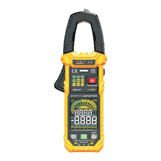
- Page 1 DIGITAL CLAMP METER 21-S...
-
Page 2: Table Of Contents
Safety Statement Safety Symbols Overview Instrument panel description Function button: Measurement Operation Power on/off Maximum/minimum value measurement Flashlight on/off Data hold Auto Power off Cancel Auto Power off SMART measurement mode Professional measurement mode AC/DC current measurement AC inrush current measurement AC/DC voltage measurement Resistance measurement Continuity test... - Page 3 Frequency/duty measurement Capacitance measurement Temperature measurement Non-contact AC Voltage Detection (NCV) Single probe live wire detection (LIVE) General Technical Specifications Accuracy Specifications DC voltage AC voltage DC current AC current Resistance Continuity Diode Capacitance Frequency/Duty Temperature Maintenance General maintenance Battery Installation or Replacement...
-
Page 4: Safety Statement
SAFETY STATEMENT Warning Read this manual before using the instrument. “ Warning” mark indicates the condition and operation which may cause danger to users. “ Caution” mark refers to the condition and operation which may cause damage to the instrument or equipment. - Page 5 each terminal and grounding point shall not exceed the rated value. • By measuring the known voltage to check whether the meter work is normal, if it is not normal or damaged, do not use it again. • Before using the instrument, please check whether there are cracks in the instrument shell or plastic parts damaged.
- Page 6 replace the battery in time in case of any measurement error. • Do not use the instrument around explosive gas, steam or in wet environment. • When using the probe, please put your fingers behind the finger protector of the probe. •...
- Page 7 High voltage warning AC (Alternating current) DC (Direct current) AC or DC Warning, important safety signs Ground Equipment with double insulation / reinforced insulation protection Low battery Product complies with all relevant European laws Inrush current measurement The additional product label shows that do not discard this electrical/electronic product into household garbage.
-
Page 8: Overview
Overview A new generation of true RMS high performance intelligent digital clamp meters that combine a wide range of functions to make your work easier, more efficient and safer. It is capable of measuring AC/DC voltage, AC/DC current, inrush current, frequency, duty cycle, resistance, capacitance, temperature, diode, continuity, NCV and more. -
Page 9: Measurement Operation
Function button: Gear function selection/intelligent measurement button Maximum/Minimum Value button Function selection/inrush current measurement button Measurement Operation Warning Do not measure voltages above 600V as this may • damage the meter. When measuring high voltage, pay special attention • to safety, so as not to be subjected to electric shock or personal injury. -
Page 10: Maximum/Minimum Value Measurement
The meter is only available for measurement. When the measurement is finished, press and hold key for about 2 seconds to switch off the meter. Maximum/minimum value measurement Press button to switch on the maximum and minimum value measurement. Press button again to cycle through the maximum and minimum values. -
Page 11: Cancel Auto Power Off
If there is no operation within 15 minutes after starting up, the meter will automatically shut down to save battery energy. Cancel Auto Power off Press and hold the key, then press the key to turn on the instrument power and then release key, the display will have no "... -
Page 12: Professional Measurement Mode
resistance, continuity, the instrument automatically identify and measure. The current is measured with the clamp, and the other measurements are taken from the pen input. Read the measurement results from the display screen. The frequency is displayed when the AC signal is measured. -
Page 13: Ac Inrush Current Measurement
measuring, press and hold the " " key to clear zero, display "ZERO" and then measure. Then press the trigger to open the clamp, clamp the conductor to be tested, slowly release the trigger until the clamp are completely closed, and determine whether the conductor to be tested is clamped in the center of the pliers, if the conductor is not in the center of the pliers, additional errors will occur. -
Page 14: Ac/Dc Voltage Measurement
whether the conductor to be tested is clamped in the center of the pliers, if the conductor is not in the center of the pliers, additional errors will occur. Turn on the device to be tested (such as the motor) and then trigger the measurement by the surge current. -
Page 15: Resistance Measurement
Resistance measurement Press the button to turn on the power supply of the meter. After the self-test is completed, the meter will display and enter the intelligent measurement mode. Press button, set the pointer to the " " position. Insert the red probe in “INPUT” jack, insert the black probe in “COM”... -
Page 16: Diode Test
indicator light is green, the screen displays the resistance. Diode test Press the button to turn on the power supply of the meter. After the self-test is completed, the meter will display and enter the intelligent measurement mode. Press button, set the pointer to the " "... -
Page 17: Frequency/Duty Measurement
function. Insert the red probe in “INPUT” jack, insert the black probe in “COM” jack. Connect the meter in parallel to the power supply or load to be tested. Read the measurement result on the screen. When the AC voltage is measured, the frequency is displayed on the display screen. -
Page 18: Temperature Measurement
the meter. After the self-test is completed, the meter will display and enter the intelligent measurement mode. Press button, set the pointer to the " " position. Insert the red probe in “INPUT” jack, insert the black probe in “COM” jack. Contact the probe to the measured circuit or Capacitance. -
Page 19: Non-Contact Ac Voltage Detection (Ncv)
Warning When measuring temperature with thermocouple, the probe of thermocouple can't touch the charged object, otherwise it may damage the instrument and may suffer electric shock or personal injury. Note : It takes a long time for the cold end of thermocouple to be restored in the instrument to achieve thermal balance with the environment. -
Page 20: Single Probe Live Wire Detection (Live)
"--H" symbol will be displayed, the beep will emit a fast beep sound, and the red LED indicator will light up. Note: Before using the NCV function, remove the stylus. Otherwise, the detection accuracy will be affected. Single probe live wire detection (LIVE) 1) Press the button to turn on the power supply of the meter. -
Page 21: General Technical Specifications
time. General Technical Specifications • Environment condition of using: CAT.III 600V Pollution level ±2 Altitude < 2000m Working environment temperature and humidity: 0~40°C (<80% RH, <10°C non- condensing). Storage environment temperature and humidity: -10~60°C (<70% RH, remove the battery). • Temperature coefficient: 0.1x accuracy/°C (<18°C or >28°C). -
Page 22: Accuracy Specifications
• Input polarity indication: automatically display “__”. • Power: 3 x 1.5V AAA batteries. Accuracy Specifications The accuracy applies within one year after the calibration. Reference condition: the environment temperature 18°C to 28°C, the relative humidity is no more than 80% accuracy: ±... -
Page 23: Ac Voltage
AC voltage Range Resolution Accuracy 600mV 0.1mV 0.001V ± (0.8%reading+5) 0.01V 600V 0.1V Input impedance : 10M Maximum input voltage: 600V. Ù Frequency Response : 40Hz ~ 1kHz(TRMS). DC current Range Resolution Accuracy 0.01A ± (2.5% reading +5) 600A 0.1A Maximum input current: 600A. -
Page 24: Resistance
Resistance Range Resolution Accuracy 0.001k 0.01k ± (1% reading +5) 600k 0.1k 0.001M 0.01M Continuity <50 , the buzzer Ù Test Voltage Approx. 1V Overload protection : sounds and the green 250V indicator LED on. Diode It displays the Reverse DC voltage is approximate forward about 3V Overload protection:... -
Page 25: Capacitance
Capacitance Range Resolution Accuracy 0.001nF 60nF 0.01nF 600nF 0.1nF µ 6µF 0.001 F ± (4.0% reading +5) 60 F µ 0.01 F µ 600 F µ 0.1 F µ 0.001mF 60mF 0.01mF Overload protection: 250V. The above accuracy does not include the error caused by the pen capacitance. -
Page 26: Temperature
Overload protection: 250V. The "mV" gear voltage measurement frequency : 1) Range: 10Hz ~ 2 kHz 2) Sensitivity of signal: >50mV(RMS), sine wave The "V" gear voltage measurement frequency : 1) Range: 10Hz ~ 2 kHz 2) Sensitivity of signal: >0.5V(RMS), sine wave The current measurement frequency : 1) Range:10Hz ~ 2 kHz 2) Sensitivity of signal: >12A(RMS), sine wave... -
Page 27: Maintenance
Maintenanc Warning To avoid electric shock, remove the test probe before opening the battery cover or back cover General maintenance • Maintenance and service of this instrument must be carried out by professional qualified maintenance personnel or maintenance department. • Use wet cloth or mild detergent regularly to clean the shell. - Page 28 Remove the old battery and install the new battery according to the polarity of the battery marked in the battery box. After installing the new battery, cover the battery cover and lock the screw. Warning • To avoid the possibility of electric shock or personal injury caused by incorrect reading, replace the battery immediately when the "...
Need help?
Do you have a question about the 21-S and is the answer not in the manual?
Questions and answers