
Related Manuals for Baxi SPC Split 150 WH


Summary of Contents for Baxi SPC Split 150 WH
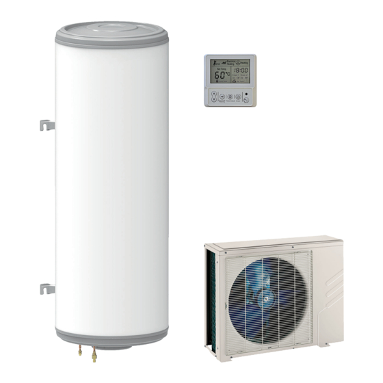
- Page 1 Installation and Service Manual Thermodynamic water heater SPC Split SPC Split 150 WH Serv. ref. SODU 2 M R1...
-
Page 2: Table Of Contents
Contents Contents Safety ................... . 4 General safety instructions . - Page 3 Contents 7.2.3 Installing the outdoor unit ..............35 7.2.4 Installing the control panel support .
-
Page 4: Safety
1 Safety Safety General safety instructions Danger This appliance can be used by children aged 8 years and above and by persons with reduced physical, sensory or mental capabilities or lack of experience and knowledge when they have been given supervision or instruction concerning the safe use of the device and understand the resulting risks. - Page 5 1 Safety Caution Draining the domestic hot water tank: 1. Shut off the domestic cold water inlet. 2. Open a hot water tap in the installation. 3. Open a valve on the safety unit. 4. When the water stops flowing, the domestic hot water tank has been drained.
- Page 6 1 Safety Warning Earthing must comply with the prevailing installation standards. Earth the appliance before making any electrical connections. Type and calibre of the protective equipment: refer to the chapter Recommended cable cross- sections. See the Installation and Service Manual. To connect the appliance to the mains supply, refer to the chapter Electrical Connections in the appliance's installation and service manual.
-
Page 7: Recommendations
1 Safety Warning In order to limit the risk of being scalded, the installation of a thermostatic mixing valve on the domestic hot water flow pipes is obligatory. Warning Only qualified professionals are authorised to work on the heat pump and the heating system. Caution The system must satisfy each point in the rules in force in the country that govern works and... -
Page 8: Specific Safety Instructions
1 Safety Specific safety instructions Warning Refrigerant fluid and pipes: Use only R134a refrigerant fluid to fill the installation. Use tools and pipe components especially designed for use with R134a refrigerant fluid. Use copper pipes deoxidised with phosphorus to carry the refrigerant fluid. Use beading to guarantee the tightness of the connections. - Page 9 1 Safety Tab.4 First aid If inhaled Evacuate the subject from the contaminated area and take him into the open air If feeling unwell: call a doctor. In the event of contact with the Treat frost injuries like burns. Rinse with copious amounts skin of tepid water, do not remove clothing (risk of adhesion to the skin)
-
Page 10: Liabilities
1 Safety Tab.8 Handling Technical measures Ventilation Precautions to be tak No smoking. Prevent the build-up of electrostatic charges. Work in a well ventilated place Tab.9 Considerations on disposal Disposal must be done in compliance with prevailing local and national regulations. Product waste Consult the manufacturer or the supplier for information on recovery or recycling... - Page 11 1 Safety Install the appliance in compliance with prevailing legislation and standards. Carry out initial commissioning and any checks necessary. Explain the installation to the user. If maintenance is necessary, warn the user of the obligation to check the appliance and keep it in good working order.
-
Page 12: Symbols Used
2 Symbols used Symbols used Symbols used in the manual This manual uses various danger levels to draw attention to special instructions. We do this to improve user safety, to prevent problems and to guarantee correct operation of the appliance. Danger Risk of dangerous situations that may result in serious personal injury. -
Page 13: Technical Specifications
2009/125/EC on the ecodesign of energy-related products. Technical data 3.2.1 Technical data Tab.11 Technical parameters for heat pump water heaters Specification Unit SPC Split 150 WH Daily electricity consumption 3.597 elec Declared load profile Sound power level, indoors ( dB (A) Sound power level, outdoors (... -
Page 14: Sensor Specifications
3 Technical specifications Specification Unit SPC Split 150 WH Storage volume (V) 150.0 Mixed water at 40 °C (V40) Operating pressure MPa (bar) 1.0 (10) Maximum water temperature °C Circuit breaker type Circuit breaker calibre Power supply voltage - Frequency... -
Page 15: Dimensions And Connections
3 Technical specifications Dimensions and connections 3.3.1 Domestic hot water tank dimensions Fig.2 SPC Split 150 WH 1225 1273 MW-2000611-1 1 Domestic hot water outlet 3 1/4” refrigeration connection 2 Domestic cold water inlet 4 3/8” refrigeration connection 3.3.2 Outdoor unit dimensions Fig.3... -
Page 16: Electrical Diagram Of The Outdoor Unit
3 Technical specifications Electrical diagram of the outdoor unit Fig.5 White Black Black Off Peak 1 2 3 Yellow LOW SPEED HIGH SPEED F A N Blue 4-WAY VALVE HN-in HL-in CN11 CN10 White Whi t e CN15 CN16 Blue Blue CAP1 Off Peak... - Page 17 3 Technical specifications Connector Description Compressor capacitor Compressor capacitor Power supply Electrical power supply E-Heater Electrical back-up OFF-PEAK Off-peak rate signal Neutral Live Earth Current transformer Differential current transformer 4–WAY VALVE 4-way valve COM1 Control panel bus LOW SPEED Low fan speed HIGH SPEED High fan speed RT5L...
-
Page 18: Description Of The Product
4 Description of the product Description of the product General description The thermodynamic water heaters in the SPC Split range have the following specifications: Accumulation domestic hot water tank, Heat pump extracting energy from the outside air, Control panel with timer programming, 1600 W shielded immersion heater, Glass-lined tank protected by magnesium anode, Very thick insulation (0% CFCs). -
Page 19: Standard Delivery
4 Description of the product Standard delivery The thermodynamic water heater is delivered in several packages: Contents of the domestic hot water tank package Contents of the outdoor unit package The domestic hot water tank The outdoor unit The documentation bag The accessories box Documentation bag Accessories... -
Page 20: Before Installation
5 Before installation Before installation Position of the data plates Fig.8 The data plates must be accessible at all times, they are used to identify the product and give the following information: Appliance type, Serial number, Electrical power supply. MW-2000383-2 Choice of the location 5.2.1 Selecting the location of the domestic hot water tank... - Page 21 5 Before installation Fig.10 75 mini 1225 1273 150l 350 mini MW-2000651-2 Fig.11 1. Choose the location of the domestic hot water tank keeping in mind the dimensions indicated opposite. 2. Choose a room that complies with the following specifications: 150 mini A room connected to an external wall to facilitate the connection between the domestic hot water tank and the outdoor unit,...
-
Page 22: Respect The Distance Between The Domestic Hot Water Tank And The Outdoor Unit
5 Before installation 5.2.2 Respect the distance between the domestic hot water tank and the outdoor unit Fig.12 A Domestic hot water tank B Outdoor unit 1 Maximum number of elbows: 15 To ensure that the thermodynamic water heater functions correctly, respect the minimum and maximum connection lengths between the domestic hot water tank and the outdoor unit. - Page 23 5 Before installation Fig.14 MW-C000373-1 Fig.15 1. Locate the noise abatement screen as close as possible to the source of noise whilst allowing for the free circulation of air in the exchanger on the outdoor unit and maintenance work. 2. Respect the following minimum positioning distances of the outdoor unit from the wall.
-
Page 24: Selecting The Location Of The Control Panel
5 Before installation Fig.16 MW-6000252-2 1. Install the outdoor unit sufficiently high off the ground to allow condensates to be discharged correctly. 2. Ensure the base meets the following specifications: Specifications Reason Maximum width equal to the width of the outdoor unit. Height at least 200 mm greater then the average depth of the This helps to protect the exchanger from snow and prevent covering of snow. -
Page 25: Connecting Diagrams
6 Connecting diagrams Connecting diagrams Connecting diagrams with external unit 6.1.1 Connection diagram Fig.18 MW-2000388-2 A Domestic hot water tank 5 Refrigeration connection out B Outdoor unit 6 Refrigeration connection in C Electrical box 7 Valve with plug D Control panel 8 Safety unit 1 Domestic hot water outlet 9 Pressure reducer... - Page 26 6 Connecting diagrams Fig.19 °C 2 30 V 5 0Hz MW-2000616-1 A Domestic hot water tank 4 Domestic hot water sensor B Outdoor unit 5 Refrigeration connection out C Electrical box 6 Refrigeration connection in D Control panel 7 Valve with plug E Instant boiler 8 Safety unit 1 Domestic hot water outlet...
-
Page 27: Connecting Diagrams Without External Unit
6 Connecting diagrams Connecting diagrams without external unit 6.2.1 Connecting diagram Fig.20 A Domestic hot water tank C Electrical box 1 Domestic hot water outlet with dielectric union 2 Domestic cold water inlet with dielectric union 3 Power supply cable for the immersion heater 5 Valve with plug 6 Safety unit 7 Pressure reducer... -
Page 28: Description Of The Safety Unit
6 Connecting diagrams Description of the safety unit Fig.22 9 Isolation valve 17 Drain valve 27 Non-return valve 28 Domestic cold water inlet 29 Pressure reducer 30 Safety unit 2 cm 54 End of the discharge pipe free and visible 2 to 4 cm above the flow (54) funnel 55 Domestic hot water diaphragm safety valve, sealed and calibrated... -
Page 29: Electrical Connection With Off-Peak/Peak Rate Cables
6 Connecting diagrams 6.4.2 Electrical connection with off-peak/peak rate cables Fig.24 Electrical Heating Error Heating Set Temp Timer 1 Timer 2 On Off On Off Electrical Timer / Enter 538 kW/h Heating Clock 15 / 45 A 500 mA C1 C2 40 A 16 A TEST... -
Page 30: Electrical Connection Diagrams Without External Unit
6 Connecting diagrams Electrical connection diagrams without external unit 6.5.1 Electrical connection without off-peak/peak rate cables Fig.26 538 kW/h 15 / 45 A 500 mA C1 C2 40 A 16 A TEST MW-5000708-1 1 Domestic hot water tank 4 AC-type differential switch 2 Meter 5 Circuit breakers 3 Connection circuit breaker... -
Page 31: Installation
7 Installation Installation Recommendations The appliances must be installed by a certified professional in accordance with prevailing statutory texts and codes of practice. The installation must comply on all points with prevailing regulations and directives, which govern work and interventions in individual homes, blocks of flats and other buildings. - Page 32 7 Installation Fig.29 4. Fix the brackets to the domestic hot water tank the correct way round, using the screws and washers on the domestic hot water tank, while supporting the appliance to avoid any tipping. MW-2000635-1 Fig.30 5. Tilt the domestic hot water tank onto its brackets. 90°...
-
Page 33: Install The Domestic Hot Water Tank To The Wall With A Tripod
7 Installation 7.2.2 Install the domestic hot water tank to the wall with a tripod The tripod option: Réf. 89788949, is mandatory when the wall to be fitted to is not strong enough to support the weight of a full domestic hot water tank. - Page 34 7 Installation Fig.33 4. Fix the brackets to the domestic hot water tank the correct way round, using the screws and washers on the domestic hot water tank, while supporting the appliance to avoid any tipping. MW-2000635-1 Fig.34 5. Tilt the domestic hot water tank onto its brackets. 90°...
-
Page 35: Installing The Outdoor Unit
7 Installation Fig.35 6. Attach the domestic hot water tank by inserting the upper bracket onto the screws. The domestic hot water tank must rest on the tripod. 7. Fasten the screws. MW-2000627-1 7.2.3 Installing the outdoor unit Installing the outdoor unit on the ground Fig.36 When mounting to the ground, install a concrete base. -
Page 36: Installing The Control Panel Support
7 Installation Installing the outdoor unit on its wall bracket Fig.37 For wall mounting, fit the wall support kit and the anti-vibration studs available separately: package EH95. The data plate must be accessible at all times. 1. Mount the wall bracket with the horizontal plane at least 200 mm above the ground. -
Page 37: Hydraulic Connections
7 Installation Hydraulic connections 7.3.1 Preparing the water connections Fig.39 1 Domestic hot water outlet (red collar) 2 Domestic cold water inlet (blue collar) The components used for the connection to the cold water circuit must comply with the prevailing standards and regulations in the country concerned. -
Page 38: Connecting The Domestic Hot Water Tank To The Cold Water Circuit
7 Installation 7.3.2 Connecting the domestic hot water tank to the cold water circuit 1. Install a pressure reducer if the mains pressure exceeds 80% of the calibration of the safety valve or unit (e.g. 0.55 MPa (5.5 bar) for a safety unit calibrated to 0.7 MPa (7 bar)). - Page 39 7 Installation Fig.41 3/8’ 1/4’ MW-2000623-1 1/4’ 3/8’ 3/8" fitting supplied on the outdoor unit supplied in the documentation bag 1/4" fitting supplied on the outdoor unit supplied on the domestic hot water tank 1. Partially unscrew the 3/8” adaptor on the domestic hot water tank. If no release noise can be heard, return the product to the after- sales service.
-
Page 40: Electrical Connections
7 Installation Electrical connections 7.5.1 Electrical recommendations Only qualified professionals may carry out electrical connections, always with the power off. Separate the very low voltage cables from the 230V circuit cables. The electrical power supply is done by means of a mains connection cable (~230 V, 50 Hz) in accordance with prevailing national regulations for electrical installations. -
Page 41: Connecting The Electrical Connections Of The Domestic Hot Water Tank With Outdoor Unit
7 Installation 7. Connect the off-peak/peak rate connector to the appropriate terminals, in the case where the off-peak signal is to be used. 8. Replace the service panel passing the cables through the passage provided for this purpose in the panel. 7.5.3 Connecting the electrical connections of the domestic hot water tank with outdoor unit... -
Page 42: Connecting The Electrical Connections Of The Domestic Hot Water Tank With No Outdoor Unit
7 Installation 7.5.4 Connecting the electrical connections of the domestic hot water tank with no outdoor unit Fig.44 The 1.5 mm section power supply cable for the electrical connection of the domestic hot water tank is provided by the installer. 1. -
Page 43: Fill The Domestic Hot Water Tank
7 Installation Fill the domestic hot water tank. Fig.46 When the water and electrical connections are made, fill the domestic hot water tank. 1. Turn on a hot water tap. 2. Check that the outdoor unit drain valve is in the closed position. 3. -
Page 44: Commissioning
8 Commissioning Commissioning Checklist before commissioning Tab.19 General checks Inspection points Checked? Position of the outdoor unit, distance from the wall Tightness of the refrigerant fittings Pressure during evacuation prior to filling Evacuation time and outside temperature during evacuation Domestic hot water tank filled with water Tab.20 Electrical checks Inspection points... -
Page 45: Checklist After Commissioning
8 Commissioning Checklist after commissioning Fig.48 A few days after the appliance is commissioned, check the installation. 1. Check the tightness of the connections. 2. Check the water pressure. 3. Check that there are no errors on the control panel. 4. -
Page 46: Setting The Parameters
9 Setting the parameters Setting the parameters For more information, see Checks after a disconnection of the mains supply, page 52 Activate / Deactivate the Holiday mode Fig.49 For extended periods away, switch the thermodynamic water heater to Holiday mode. The Holiday mode should be used rather than shutting down the thermodynamic water heater to ensure the following functions operate: Frost protection,... -
Page 47: Set The Temperature Threshold For The Electrical Back-Up Function
9 Setting the parameters Set the temperature threshold for the electrical back-up function Fig.50 The electrical back-up function is authorised to operate when the outside temperature falls below a certain threshold. This threshold can be adjusted. 1. Press the key for 3 seconds. The Electrical Heating and Set Temp icons flash. -
Page 48: 10 Maintenance
10 Maintenance 10 Maintenance 10.1 General Caution Do not neglect to service the domestic hot water tank or the heat pump. Contact a qualified professional or take out a maintenance contract for the obligatory annual servicing of the thermodynamic water heater. Failure to service the appliance voids the warranty. -
Page 49: Maintenance Of The Outdoor Unit
10 Maintenance 10.4 Maintenance of the outdoor unit 10.4.1 Checking the cooling circuit 1. Power off the thermodynamic water heater before any interventions on the appliance. Certain items of equipment such as the compressor and the pipes can reach temperatures in excess of 100 °C and high pressures, which may cause serious injuries. -
Page 50: Removing The Inspection Hatch
10 Maintenance 10.5.2 Removing the inspection hatch Checking operations such as descaling and checking the magnesium anode require the domestic hot water tank to be drained and the inspection hatch removed. Fig.52 230V MW-2000405-3 1. Drain the domestic hot water tank. 2. -
Page 51: Checking The Magnesium Anode
10 Maintenance 4. Remove limescale deposits from the bottom of the tank. 5. Replace the inspection hatch. 6. Fill the domestic hot water tank. For more information, see Draining the domestic hot water tank, page 49 Removing the inspection hatch, page 50 Replacing the inspection hatch, page 51 10.5.4 Checking the magnesium anode... -
Page 52: Checks After A Disconnection Of The Mains Supply
10 Maintenance Fig.54 1. Fit the new gasket positioning the tab outwards between two screws. 2. Refit the inspection hatch. Note the position of the tab. Note the position of the round terminal of the anode wire. 3. Connect the earth wire. 4. -
Page 53: 11 Troubleshooting
11 Troubleshooting 11 Troubleshooting 11.1 Resetting the safety thermostat Fig.55 The thermostat is factory-set to 65 °C (average storage temperature). A thermal safety cut-out is integrated into the safety thermostat. It stops water from being reheated should accidental overheating occur. Remove the cause of the overheating and then reset the safety thermostat. - Page 54 11 Troubleshooting Code Description Causes and corrective actions Communication fault: check the connection. Air temperature sensor T4 error Damaged sensor: replace the sensor. Communication fault: check the connection. Air suction temperature sensor Th error Damaged sensor: replace the sensor. Communication fault: check the connection. Air discharge temperature sensor Tp error Damaged sensor: replace the sensor.
-
Page 55: Clearing The Error Codes
11 Troubleshooting Code Description Causes and corrective actions Error on the main controller Main controller damaged: replace the main controller. Domestic hot water tank installed in a room exposed to frost: install the domestic hot water tank in a frost- Frost protection running free room. - Page 56 11 Troubleshooting Parameter No. Description of the parameter Values displayed Intake temperature (Th) Discharge temperature (Tp) Electrical current required: to the electrical back-up, to the compressor Degree to which the electronic pressure release Open = value displayed x 8 valve is open Setpoint temperature (Ts) Trip temperature of the electrical back-up (Td) Hysteresis (Tr)
-
Page 57: 12 Disposal And Recycling
12 Disposal and recycling 12 Disposal and recycling 12.1 Switching the thermodynamic water heater off Fig.58 1. Power off the thermodynamic water heater before any interventions on the appliance. 2. Disconnect the water supply to the domestic hot water tank. 3. -
Page 58: 13 Appendix
13 Appendix 13 Appendix 13.1 Maintenance form for the installer Tab.27 Maintenance carried out by the installer Operation Periodicity Check the cleanliness of the outdoor unit fan once a year Descaling the domestic hot water tank after the first year of and then every two years Checking the magnesium anode... - Page 59 © Copyright All technical and technological information contained in these technical instructions, as well as any drawings and technical descriptions supplied, remain our property and shall not be multiplied without our prior consent in writing. Subject to alterations.
- Page 60 36061 BASSANO DEL GRAPPA (VI) - ITALY Via Trozzetti, 20 Servizio clienti: Tel +39 0424 517800 - Fax +39 0424 38089 www.baxi.it 7740327 - v03 - 03122019 7740327-001-03...
Need help?
Do you have a question about the SPC Split 150 WH and is the answer not in the manual?
Questions and answers