
Related Manuals for Hella ELEGANZA


Summary of Contents for Hella ELEGANZA
- Page 1 Installation Instructions These instructions must be read prior to installation and use! Pergola awning ELEGANZA / ELEGANZA protect...
-
Page 2: Table Of Contents
Installation Instructions Table of Contents Preliminary remarks HELLA Pergola awning ELEGANZA / ELEGANZA protect ....3 Before installation ......................... 4 Overview: Tools for the installation ..................5 Overview ELEGANZA ......................6 Column types’ overview ......................7 Installation box ........................8 Installing the guide rails ...................... -
Page 3: Preliminary Remarks Hella Pergola Awning Eleganza / Eleganza Protect
Preliminary remarks HELLA Pergola awning ELEGANZA / ELEGANZA protect With this HELLA product you have opted for a high-quality product with a most up-to-date technology that can nevertheless be easily installed and operated. In these instructions we describe the basic installation, commissioning and use. -
Page 4: Before Installation
Installation Instructions Before installation Check the product immediately for possible shipping damage and for compliance with the delivery receipt. If parts are missing or damaged, please consult your supplier immediately. Check the mounting base and ensure that the mounting material to be used complies with the given conditions to guarantee proper installation. -
Page 5: Overview: Tools For The Installation
Installation Instructions Overview: Tools for the installation Battery-powered drill Drilling bit Depending on the mounting Drill set base (Bit AW 10, AW 20) acc. to Mounting base Bit extension Level Measuring tape Pencil Screwdriver Spanners Allen key or ratchet Combination pliers or Side cutter long-nosed pliers Subject to technical modifications. -
Page 6: Overview Eleganza
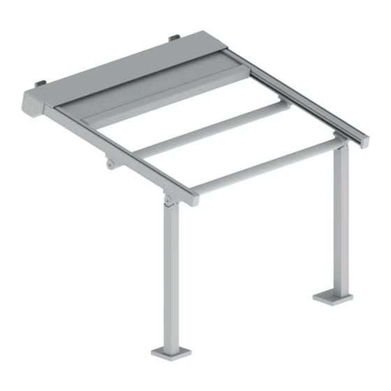
Installation Instructions Overview ELEGANZA Legend Box (2-part) With column fixed (standard) Wall bracket Type A Conduit Lateral end cap Anti-lift device Guide rail Curtain and front rail Cross-beam round Subject to technical modifications. – Date of Issue September/2023... -
Page 7: Column Types' Overview
Installation Instructions Column types’ overview fixed column (std) lowerable column (optional) Important information regarding the usage of a lowerable column: - Only one column may be lowerable per unit. - In the case of combined units, centre columns must not be lowerable under any circumstances, i.e. -
Page 8: Installation Box
Installation Instructions Installation box Slide in suspension brackets Take the box out of the cardboard packaging and remove the foils. Place the box on two prepared trestles. Remove the lateral covering caps (1). For this, loosen the countersunk screw (2) in the upper covering profile (3). - Page 9 Installation Instructions Installation box Distribute the suspension brackets Divide the hanging consoles (2) evenly over the width of the box. Make sure that the edge distances (<=500 mm) of the outer brackets are not exceeded. Clamp the brackets by tightening the threaded pins (1).
- Page 10 Installation Instructions Installation box Mounting the mounting brackets on the wall Draw the mounting positions of the wall brackets (2) on the wall. The distance between the two outer wall brackets corresponds to the previously measured dimension B. Please refer to the order papers for the mounting height (1).
- Page 11 Installation Instructions Installation box Screwing in the threaded pins and securing them Put the threaded bolt (1) from the mounting material into the passage in the hanging console (2) and then turn it through the thread on the other side of the hanging console.
- Page 12 Installation Instructions Installation box Screwing in the threaded pins and securing them Secure the threaded bolt additionally by screwing the threaded pin (1) into the threaded hole in the hanging console (2). Legend Threaded pin M4x4 Hanging console Removing the transportation lock Loosen the threaded pin (2).
-
Page 13: Installing The Guide Rails
Installation Instructions Installing the guide rails Preparations single guide rail before mounting Mounting the guiding tube holder and the holder for the cross brace on the guide rail Place the guide rails (1) on two prepared trestles. Push the sliding blocks (6) - 2 per bracket - into the groove of the guide rail. - Page 14 Installation Instructions Installing the guide rails Preparations double guide rail before mounting Mounting the guiding tube holder and the centre joint on the guide rail Place the double guide rail on two prepared trestles. Push the sliding blocks (4) - 2 per bracket - into the groove of the guide rail. Screw the conduit bracket (1) and the conduit bracket (2) with the sliding blocks (4).
- Page 15 Insert the runners (6) of the front rail (1) into the channel provided in the guide rail. Only with ELEGANZA protect: With ELEGANZA protect systems, the zip fastener (5) of the cover must be threaded into the inner guide strips (4) beforehand.
- Page 16 Installation Instructions Installing the guide rails Place the guide rails onto the box. Attention for systems with Varioplus: For systems with Varioplus roller blind, make sure that the protruding retraction aid (4) on the drive side guide rail (5) is guided out at the corresponding point in the side part (3).
-
Page 17: Installation Of The Columns
Installation Instructions Installation of the columns Marking the column position Mark the mounting positions of the columns on the floor. Please take the column distance (1) from the order and measure it from the wall (fixing level) to the middle of the column. - Page 18 Installation Instructions Installation of the columns Swivelling the unit open Swivel the unit up evenly on both sides. Hold the unit in position. Take the column and place it under the guide rail. To do this, slide the bracket for the cross-beam (1) over the attachment (2), which is mounted on top of the column.
- Page 19 Installation Instructions Installation of the columns Swivelling the unit open To be noted at the middle situation! When you have swivelled the unit upwards, hold it in position. Then place the double guide rail (3) on the centre column. Make absolutely sure that the middle hinge (1), which is mounted on the guide rail, rests on the attachment (2) of...
- Page 20 Installation Instructions Installation of the columns Aligning the unit 90° 90° Place the columns in the previously marked positions. Remeasure the diagonals (1) and the widths (2, 3). The diagonal dimension as well as the width dimensions must be equal. Verify that the guide rails are perpendicular to the box.
- Page 21 Installation Instructions Installation of the columns Screw column feet to the floor Bore the holes for the anchor bolts (3) using an appropriate drill (1). Clean the remaining dirt/dust (blow out) from the boreholes and drive the anchor bolts (3) into the boreholes.
-
Page 22: Cross Brace Installation (Front)
Installation Instructions Cross brace installation (front) for single units The covering cap (1) for the column base must be fitted before inserting the front cross-beam (3). To do this, push the covering cap (1) over the column from above. The screw (2) must be removed again for this. - Page 23 Installation Instructions Cross brace installation (front) for installation combinations Start element: Place the front cross-beam (1) from above between the columns and screw the cross-beam to the columns on both sides. Use the screws (2) / (4) from the mounting material for this.
- Page 24 Installation Instructions Cross brace installation (front) for installation combinations Middle and end element Push the stainless steel bolt (2) from the mounting material through the slot in the attachment of the middle hinge. Push the bolt in until it rests in the borehole in the already mounted middle hinge (3).
- Page 25 Installation Instructions Cross brace installation (front) for installation combinations Middle and end element Screw the middle hinge (4) with the sliding blocks in the guide rail, by using the screws (1) from the mounting material. Secure the bolt in the attachment (3) of the column by screwing the screw (2).
-
Page 26: Installation Pull Cords
Installation Instructions Installation pull cords - Place the pull cords over the runner in the awning box (1). - Guide the pull cords in the channel for the runners up to the deflection roller in the crosshead (5). (The pull cords must be threaded through in the guide rail behind the runners of the carriage). - Page 27 Installation Instructions Installation pull cords The installation and removal of the pull cords should be performed by two persons. Do not twist the pull cords! To release the pull cord fasteners, remove the small plugs (6) from the carriages (2) and relieve the strain on the pull cords by pulling them in the direction of the drop profile.
-
Page 28: Installing The Lateral End Caps
Installation Instructions Installing the lateral end caps Put the lateral cover caps (1) onto the side parts (2) of the awning box. The positioning nipples (3) must protrude into the recesses of the side parts. Due to the screwed magnets (4), the cover caps are then independently holding onto the side part (2). -
Page 29: Installation Of The Guiding Tubes
Installation Instructions Installation of the guiding tubes Insert the conduit (1) between the conduit brackets (3). Screw the conduit with the screws (2) from the mounting material. If necessary, align the conduit brackets. (ensure equal distances) Pay attention to the different arrangement of the conduits in case of 1 or 2 conduits. -
Page 30: Installing The Anti-Lift Device
Installation Instructions Installing the anti-lift device Slide the slot stones (1) into the groove of the guide rails (2). Then screw one clamping part on the spring side (3) and one clamping part on the clamping side (4) per unit to the slot stones. Use the provided fastening screws (5). - Page 31 Installation Instructions Installing the anti-lift device The anti-lift device (1) may always only be mounted directly above a conduit bracket (2). Through tensioning the wire cable, the guide rails could then otherwise be contracted. This can have a negative impact on the installation’s functionality.
-
Page 32: Mounting Varioplus Roller Blind - Freely Suspended
Installation The Varioplus roller blind is delivered already complete and only needs to be installed in the structure of the ELEGANZA. A Varioplus roller blind can only be used in conjunction with rigid (non-lowerable) columns. The drive side of the Varioplus (1) is always on the drive side of the unit. -
Page 33: Mounting Varioplus Roller Blind - Rail-Guided
Installation The Varioplus roller blind is delivered already complete and only needs to be installed in the structure of the ELEGANZA. A Varioplus roller blind can only be used in conjunction with rigid (non-lowerable) columns. The drive side of the Varioplus (1) is always on the drive side of the unit. - Page 34 Installation Instructions Mounting Varioplus roller blind - rail-guided Installation Connect the Varioplus roller blind (2) to an appropriate setting cable and extend the blind approx. 300 mm. Take the enclosed guide rails (7) and insert the downpipe insert (9). Repeat this on the opposite side.
- Page 35 Installation Instructions Mounting Varioplus roller blind - rail-guided Installation Screw the guide rail (7) onto the column profile (6) with the enclosed screws, using a cordless screwdriver. Pay attention to the distances of the boreholes and the position of the guide rail (7), to avoid untrue drilling.
- Page 36 Installation Instructions Mounting the Varioplus roller blind Wiring For units with Varioplus roller blinds, the drive-side guide rail (1) is already prepared for a cable duct at the factory. It is delivered with a long hole milling as well as a retracted retraction aid (2). Connect cable (3) from the Varioplus roller blind to the end of the retraction aid (2), which protrudes from the long hole.
- Page 37 Installation Instructions Mounting the Varioplus roller blind Wiring Fix the cable (3) from the Varioplus roller blind with cable ties (4) to the side part at the recesses provided for the purpose. Legend Varioplus roller blind cable Cable tie Subject to technical modifications. – Date of Issue September/2023...
-
Page 38: Installation/Wiring Led
Installation Instructions Installation/wiring LED View: Box in delivery condition View: Box with mounted guide rails (LED in box and guide rails) In the delivery condition, the supply line (2) for the LED control unit and the connecting cables (with STAK2) for the LED strips protrude from the upper covering profile (1). Depending on the order, that can be up to three such connecting cables (3/4/5). - Page 39 Installation Instructions Installation/wiring LED Detail cable outlet LED in box With LED in the boxthe cable of the LED strip (6) comes out of the groove of the floor profile (9). With LED in the guide railthe cable of the LED strip (7/8) comes out between the side part (10) and the floor profile (9).
- Page 40 Installation Instructions Installation/wiring LED Tighten the cables of the LED strips and the cable of the LED control unit tautly and fix them with cable ties (11) on the side part (12). There are recesses (13) in the side part (12), where the cable ties can be threaded through.
-
Page 41: Malfunctions
Installation Instructions Malfunctions What is the matter, if..the front rail moves to the awning box askew? The awning(s) was/were not diagonally aligned during installation. Solution: Measure the diagonal as described in Chapter “Aligning the unitd align the awning accordingly. The tension on the right side or guide rail is too high or too little on the left side or guide rail. - Page 42 Installation Instructions Malfunctions What is the matter, if..the front rail moves centrally to the awning box? The tension is too high on both sides. Solution: Check the tension as described in Chapter “Installation of the pull cords”. If necessary, take off one lapping of the pull cords of the tape pulleys.
- Page 43 Installation Instructions Malfunctions What is the matter, if..the cover slacks in the extended condition? The tension is too low on one or both sides. Solution: Check the tension as described in Chapter “Installation of the pull cords”. Place an additional lapping of the pull cords on the tape pulleys if necessary.
-
Page 44: Wiring Diagram For Motors With Onyx.connector
Installation Instructions Wiring diagram for motors with ONYX.CONNECTOR Legend Junction box ONYX. CONNECTOR Motor Hirschmann STAK 3 Hirschmann STAS 3 STAS 3 for power supply 1 Neutral conductor N 2 Phase L 3 Connection 3 not assigned 4 Protective conductor PE ONYX.CONNECTOR STAS 3 STAK 3 for motor... -
Page 45: Wiring Diagram For Motors With Onyx.node
Installation Instructions Wiring diagram for motors with ONYX.NODE Legend Junction box ONYX.NODE Button Motor ONYX.NODE LOCAL MOTOR For more details on the electrical connections, instructions for use and programming, please refer to the section “Instructions for use and configuration with ONYX” or the supplied documents. Subject to technical modifications. -
Page 46: Wiring Diagram For Motors With Somfy Io
For more details concerning the electrical connections, powers, operating instructions and programming, please refer to the enclosed documents of the manufacturer or the HELLA installation instructions. With the radio system Somfy io all receivers must be taught one after another (order does not matter), i.e. do not connect several receivers to the network at the same time as the radio system does not support a simultaneous teaching process of multiple components. -
Page 47: Wiring Diagram For Motors With Switch Operation
For more details concerning the electrical connections, powers, operating instructions and programming, please refer to the enclosed documents of the manufacturer or the HELLA installation instructions. It is essential that switches for the awning drive be electrically and mechanically locked. -
Page 48: Wiring Diagram For Led Lighting Onyx/Somfy Io
Installation Instructions Wiring diagram for LED lighting ONYX/Somfy io Legend Junction box Control unit LED ONYX/Somfy io Connection of LED strips 230 V AC 24 V DC LED 1 LED 2 LED 3 For more details concerning the electrical connections, instructions for use and programming, for “ONYX”, please refer to the section “Instructions for use and configuration with ONYX”, or the supplied documents for ONYX and Somfy. -
Page 49: Operating Instructions And Configuration With Onyx
Operating instructions and configuration with ONYX General Before configuring, download HELLA’s free app ONYX from the App store/Google Play to your smart phone. Before you can use the unit with ONYX.CENTER or ONYX.CLICK, it must be added in the ONYX app. You will find additional information regarding the configuration in the instructions for ONYX.CENTER / ONYX.CLICK... -
Page 50: Instructions For Use And Configuration With Somfy
Installation Instructions Instructions for use and configuration with Somfy Please refer to the enclosed instructions of the manufacturer for the Somfy unit operating possibilities via control devices. Subject to technical modifications. – Date of Issue September/2023... -
Page 51: Activation Guidelines For Electric Drives
Installation Instructions Activation guidelines for electric drives The motors we use are drives with integrated planetary gear, brakes, limit stops at the top and at the bottom, and thermo cut-off switches, also not only a motor, but a complete drive system. In some respect, the drives do NOT correspond to other household electrical consumers. -
Page 52: Commissioning/Functional Check
Installation Instructions Commissioning/functional check Extend and retract the unit in and out completely. When extending the unit for the first time, make sure no one is in the operating radius or standing below the unit. Make sure that during the later operation the units can be extended freely and without blockings. -
Page 53: Removal
Installation Instructions Removal Switch the unit dead and take safety precautions against unintentional switching on. The removal is carried out in reverse order to the installation. Attention: The threaded bolt (see chapter Installation box) that is screwed into the mounting bracket, may be only removed when the guide rails have been disassembled. - Page 54 For questions, wishes and ideas: HELLA Infoline +43/(0)4846/6555-0 HELLA Sonnen- und Wetterschutztechnik GmbH A-9913 Abfaltersbach, No. 125 Phone: +43/(0)4846/6555-0 Fax: +43/(0)4846/6555-134 e-mail: office@hella.info Internet: http://www.hella.info...
Need help?
Do you have a question about the ELEGANZA and is the answer not in the manual?
Questions and answers