Advertisement
Advertisement
Table of Contents

Subscribe to Our Youtube Channel
Related Manuals for real living 28WM20541-16001


Summary of Contents for real living 28WM20541-16001
-
Page 3: Important Instructions
GENERAL BEST PRACTICES FOR ASSEMBLY: Read all instructions before starting Clear a flat covered space to begin Always best to do it with a friend Note that hardware required is provided for every step Pay attention to orientation CAUTION • Before assembly and/or installation, carefully unwrap all parts. •... -
Page 4: Product Specifications
IMPORTANT INSTRUCTIONS(CONT’D) 7. Do not use outdoors. 8. This heater is not intended for use in bathrooms, laundry areas and similar indoor locations. Never locate this appliance where it may fall into a bathtub or other water container. 9. Do not run cord under carpeting. Do not cover cord with throw rugs, runners or the like. Arrange cord away from traffic areas and where it will not be tripped over. -
Page 5: Parts List
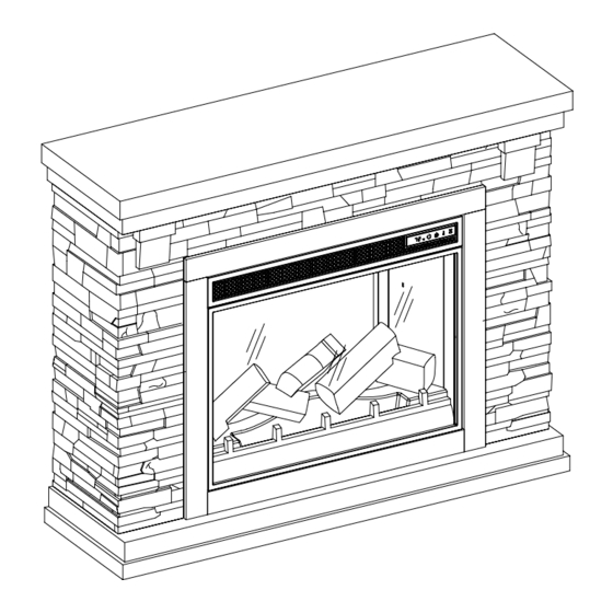
PARTS LIST Mantel Fireplace Insert Remote HARDWARE LIST Tipping Restraint Hardware PREPARATION Before beginning assembly of product, make sure all parts are present. Compare parts with package contents list and hardware contents list. If any part is missing or damaged, do not attempt to assem- ble, install or operate the product. - Page 6 STEP 1 Unpacking the fireplace insert • Using scissors, cut the rope securing the fireplace insert. not included Assembled View:...
- Page 7 STEP 2 Installing the Tip Restraint Hardware • When the Tipping Restraint Hardware (AA) is properly installed, it can provide protection against unexpected tipping of the Unit due to small tremors, bumps or climbing. • Each Tipping Restraint Hardware (AA) includes one Unit Anchor, one Wall Anchor, one Anchor Tether, and two Anchor Screws.
- Page 8 MAXIMUM RECOMMENDED WEIGHT LOADS MAXIMUM LOAD 6.8 kg / 15 lb WARNING Loads heavier than the maximum weights specified may result in instability, causing tip over resulting in death or serious injury.
- Page 9 OPERATING INSTRUCTIONS CONTROL PANEL LOCATION ICON DESCRIPTION FUNCTION The POWER button supplies power to all the POWER functions of the heater. Pressing the POWER button again will put the heater in standby mode. Holding the Power button on the control panel for 10 seconds will disable the heater function.
- Page 10 OPERATING INSTRUCTIONS (CONT’D) TEMPERATURE INCREASE / The up and down buttons “ ” on the remote will DECREASE increase / decrease temperature setting. The thermostat setting range is 62°F - 82°F( 17°C - 27°C) or continuously ON. The thermostat is adjustable by 2°F or 1°C increments. Pressing the timer button will cycle through the timer TIMER settings: 30 minutes, 1 Hour, 2H, 3H, 4H, 5H, 6H, 7H, 8H,...
-
Page 11: Troubleshooting
TROUBLESHOOTING PROBLEM POSSIBLE CAUSE CORRECTIVE ACTION Unplug the fireplace, remove the back panel of the heater box and check that the thermostat is The thermostat sensor is Display shows“ ” plugged into the main circuit board. If this does not broken or disconnected. -
Page 12: Fcc/Ic Information
FCC/IC INFORMATION Warning: Changes or modifications to this unit not expressly approved by the party responsible for compliance could void user’s authority to operate the equipment. NOTE: This equipment has been tested and found to comply with the limits for Class B digital device, pursuant to part 15 of the FCC Rules. -
Page 13: Replacing The Remote Control Battery
REPLACING THE REMOTE-CONTROL BATTERY NOTE: Do not mix old and new batteries. Do not mix alkaline, standard (carbon zinc), or rechargeable (nicad, ni-mh, etc.) batteries. NOTE: Battery disposal Please always dispose of batteries at a suitable recycling point. CAUTION: • Do not ingest batteries. •... -
Page 14: Year Limited Warranty
1-YEAR LIMITED WARRANTY The manufacturer warrants that your new Electric Fireplace is free from manufacturing and material defects for a period of one year from date of purchase, subject to the following conditions and limitations. 1. Install and operate this appliance in accordance with the installation and operating instructions furnished with the product at all times. -
Page 15: Replacement Parts List
REPLACEMENT PARTS LIST PART PART NAME PART NUMBER Flame Circuit Board Y21-S307-P40 Flame Generator Drive Motor P10-6-QCF Control Circuit Board Y21-S306-P184CF Control Panel Circuit Board Y21-S306-P32CF Main Circuit Board Y21-S306-P15-HDCF Ember bed with log set Y21-S306-P02CF Thermostat Sensor INS-NTC-TMCF Blower/ Heater assembly Y21-S306-P01CF Front Panel with frame Y21-S306-P27CF...
Need help?
Do you have a question about the 28WM20541-16001 and is the answer not in the manual?
Questions and answers