
Related Manuals for GreenWorks ELITE LB-430-T


Summary of Contents for GreenWorks ELITE LB-430-T
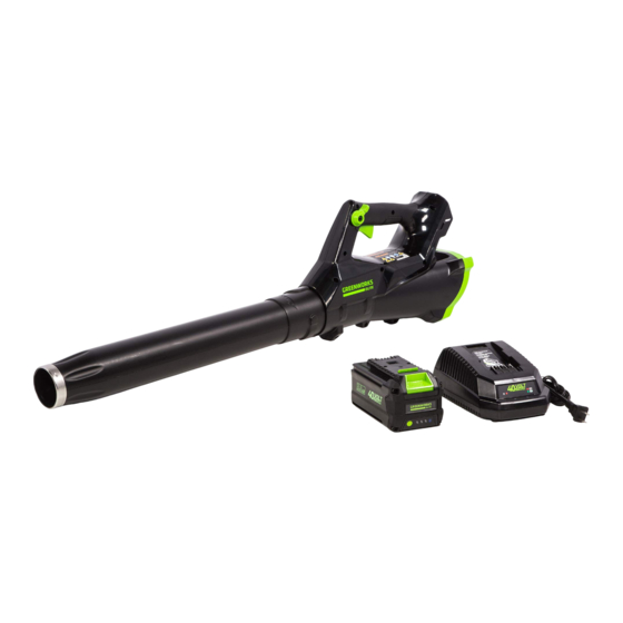
- Page 1 40V LITHIUM-ION AXIAL BLOWER LB-430-T Owner’s Manual TOLL-FREE HELPLINE: 1-833-493-5483 www.greenworkselite.com Read all safety rules and instructions carefully before operating this tool.
-
Page 2: Table Of Contents
CONTENTS Contents ........................... 2 Product Specifications ......................2 General Safety Rules ........................ 3 Symbols ............................ 6 Know Your Blower ........................8 Assembly Instruction ....................... 9 Operation Instruction.......................11 Maintenance ..........................14 Environmentally Safe Battery Disposal ..................15 Troubleshooting ........................16 Limited Warranty........................17 Exploded View .......................... -
Page 3: General Safety Rules
IMPORTANT SAFETY INSTRUCTIONS READ ALL INSTRUCTIONS BEFORE USING (THIS POWER TOOL) W A R N I N G Read and understand all instructions before using this product. Failure to follow all instructions listed below may result in electric shock, fire, and/or serious personal injury. When using an electrical appliance, basic precautions should always be followed, including the following: 1. - Page 4 • Keep all bystanders, children, and pets at least 50 ft. (15 m) away. • Use only with Greenworks Elite Batteries: L-300, L-600. • Use only with Greenworks Elite Chargers: C-220, C-400.
- Page 5 IMPORTANT SAFETY INSTRUCTIONS • Have servicing performed by a qualified repair person using only identical replacement parts. This will ensure that the safety of the product is maintained. 4. CHILD SAFETY Tragic accidents can occur if the operator is not aware of the presence of children. •...
-
Page 6: Symbols
SYMBOLS Some of the following symbols may be used on this product. Please study them and learn their meaning. Proper interpretation of these symbols will allow you to operate the product better and safer. SYMBOL NAME DESIGNATION/EXPLANATION Volts Voltage Amperes Current Hertz Frequency (cycles per second) - Page 7 SYMBOLS The following signal words and meanings are intended to explain the levels of risk associated with this product. SYMBOL SIGNAL MEANING Indicates an imminently hazardous situation, which, if not DANGER avoided, will result in death or serious injury. Indicates a potentially hazardous situation, which, if not WARNING avoided, could result in death or serious injury.
-
Page 8: Know Your Blower
KNOW YOUR BLOWER Variable Speed Trigger Cruise Control Lever Blower Tube Fig. 1 KNOW YOUR BLOWER (See Figure 1.) The safe use of this product requires an understanding of the information on the product and in this operator’s manual as well as a knowledge of the project you are attempting. Before use of this product, familiarize yourself with all operating features and safety rules. -
Page 9: Assembly Instruction
ASSEMBLY INSTRUCTION UNPACKING This product requires assembly. • Carefully remove the product and any accessories from the box. Make sure that all items listed in the package contents section are included. • Inspect the product carefully to make sure no breakage or damage occurred during shipping. •... - Page 10 ASSEMBLY INSTRUCTION W A R N I N G To prevent accidental starting that could cause serious personal injury, always remove the battery pack from the tool when assembling parts. BLOWER TUBE ASSEMBLY (See Figure 2-3.) • Align either of the grooves on the blower with the tabs on the blower tube. Push the tube into the blower until the tabs engage the grooves.
-
Page 11: Operation Instruction
OPERATION INSTRUCTION W A R N I N G Do not allow familiarity with this product make you careless. Remember that a careless fraction of a second is sufficient to inflict serious injury. W A R N I N G Always wear eye protection with side shields marked to comply with ANSI Z87.1, along with hearing protection. - Page 12 OPERATION INSTRUCTION BATTERY IMPORTANT! The battery pack is not charged when it is purchased. Before using the blower for the first time, place the battery pack in the battery charger and charge. Make sure to read all safety precautions, and follow the instructions in the Battery Charger section. To Remove (See Figure 4.) 1.
- Page 13 OPERATION INSTRUCTION STARTING/STOPPING THE BLOWER (See Figure 5.) • Ensure that the battery is installed in the blower. • Squeeze the trigger to start the blower. • To change speed, Press or release trigger to increase or decrease the speed. Cruise Control Lever Trigger FIG.5...
-
Page 14: Maintenance
MAINTENANCE W A R N I N G In order to avoid personal injury and the risk of fire and electric shock, remove the battery pack before adjusting, inspecting, or cleaning the blower. CLEANING • Remove the battery pack. • Brush or blow dust and debris out of the air vents using compressed air or a vacuum. Keep the air vents free of obstructions, sawdust, and wood chips. -
Page 15: Environmentally Safe Battery Disposal
ENVIRONMENTALLY SAFE BATTERY DISPOSAL The following toxic and corrosive materials are in the batteries used in this blower battery pack: Lithium-Ion, a toxic material. W A R N I N G All toxic materials must be disposed of in a specified manner to prevent contamination of the environment. -
Page 16: Troubleshooting
TROUBLESHOOTING PROBLEM POSSIBLE CAUSE SOLUTION Check to ensure the battery is fully Battery is not secure. connected to the blower. Press down on the battery until the latches click together. Unit will not blow. Charge the battery pack according to the Battery is not charged. -
Page 17: Limited Warranty
(4) years against defects in materials, parts or workmanship. GREENWORKS ELITE, at its own discretion will repair or replace any and all parts found to be defective, through normal use, free of charge to the customer. This warranty is valid only for units which have been used for personal use that have not been hired or rented for industrial/commercial use, and that have been maintained in accordance with the instructions in the owners’... -
Page 18: Exploded View
EXPLODED VIEW... -
Page 19: Parts List
PARTS LIST PART NO. DESCRIPTION 311062280 KIT, RIGHT HANDLE 311072280 KIT, RIGHT HOUSING 311082280 KIT, CIRCUIT BOARD 311092280 KIT, SWITCH, TRIGGER 311102280 KIT, INLET GUARD 311112280 TUBE, ASSEMBLY 311122280 KIT, MOTOR 311142280 SWITCH, ASSEMBLY 311152280 KIT, LEFT HOUSING 311162280 KIT, LEFT HANDLE... - Page 20 Greenworks Tools PO Box 1238 Mooresville, NC 28115 TOLL-FREE HELPLINE: 1-833-493-5483 Rev: 00 (07-07-17)
Need help?
Do you have a question about the ELITE LB-430-T and is the answer not in the manual?
Questions and answers