
Related Manuals for Intel 1000SX


Summary of Contents for Intel 1000SX
- Page 1 1000SX Module and 1000LX Module for 500 Series Switches User Guide Get other manuals https://www.bkmanuals.com...
- Page 2 1000SX Module and 1000LX Module for 500 Series Switches User Guide 715236-001 Get other manuals https://www.bkmanuals.com...
- Page 3 Copyright © 1998, Intel Corporation. All rights reserved. Intel Corporation, 5200 NE Elam Young Parkway, Hillsboro, OR 97124-6497 Intel Corporation assumes no responsibility for errors or omissions in this manual. Nor does Intel make any commitment to up- date the information contained herein.
-
Page 4: Quick Start
Quick Start This product contains fiber-optic ports. For Optical Safety, Warning for 1000SX never look directly at the fiber TX laser port and fiber cable ends when they are powered-up. CLASS 1 LASER PRODUCT This product contains fiber-optic ports. For Optical Safety,... - Page 5 To differentiate these modules from other modules in the text, we shall refer to both these modules as ‘1000Base Module’. ® Follow these instructions to install a 1000Base Module in your Intel Installing the module Express 500 Series Switch: Warning These modules are not designed to be installed in, or removed from, the switch while it is in operation.
- Page 6 C H A P T E R 1 Quick Start Remove the plate covering expansion slot A, unless the switch is in or to be used in a stack with redundancy. Note For a stack with redundancy, install the module on the same side of the switch as the Matrix Module it is to be connected to.
- Page 7 C H A P T E R 1 Quick Start Configure the module using Intel Device View and cable up using Configure and cable the stacking cables in the Stack Interface Module sockets and a fiber op- module tic cable with SC connectors in the RX and TX sockets. Verify the links using the LEDs.
- Page 8 To differentiate these modules from other modules in the text, we shall refer to both these modules as ‘1000Base Module’. The 1000Base Module can only be used with Intel 500 Series Switch- When to use the module es. It provides a high-speed link between the switch or group of switches containing this module and another device, switch or group of switches.
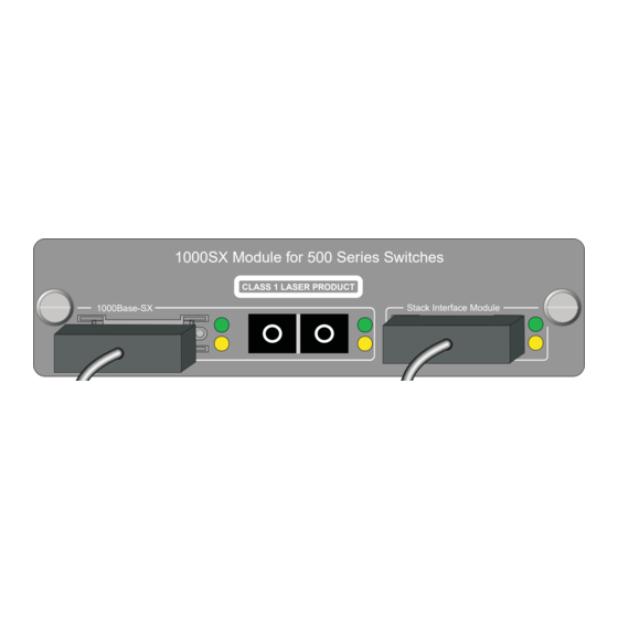
- Page 9 SC connector. To install the module, follow the instructions in Chapter 1. Installing the module The front panel of the 1000SX Module is shown below: View of the 1000SX front panel 1000SX Module for 500 Series Switches...
-
Page 10: Module Leds
2 1000SX and 1000LX Modules Module LEDs The 1000Base Module has three connectors. Each connector has two Understanding the LEDs LED indicators: Status Indicates No lights Port enabled, no link. Green, solid Link. Green, blinking Link with data traffic. Green, solid and Port disabled by a fault. - Page 11 Get other manuals https://www.bkmanuals.com...
-
Page 12: Configure The Module
The configuration and cabling of the 1000Base Module are very Introduction closely linked. Only after both processes are complete will the switch function properly. Note When the module mode is changed, the configuration is ® automatically saved and Intel Device View resets the switch. Get other manuals https://www.bkmanuals.com... -
Page 13: Configuring The Module
1000Base Module displayed in the Device mode using Intel Device View window: View Warning Changing mode causes Intel Device View to save the switch configuration and reset the switch. Right-click the 1000Base-SX/1000Base-LX port on the module and select Port Setup. Click the Module tab. -
Page 14: Standalone Mode
Module, a Matrix Module or a 1000Base Module set in stack mode. Plug the SC connectors on the optic fiber cable into the RX and TX sockets on the 1000Base-SX/1000Base-LX connector. 1000SX Module for 500 Series Switches CLASS 1 LASER PRODUCT 1000Base-SX Stack Interface Module... -
Page 15: Stack Mode
Plug the Stacking Cable (Intel Order Code: ES500SC) into the Stack Interface Module connector on the 1000Base Module, and secure it using the latches on the connector. - Page 16 Matrix Module User Guide. Plug a Stacking Cable (Intel Order Code: ES500SC) into the Stack Interface Module connector on the 1000Base Module, and secure it using the latches on the connector.
- Page 17 Plug a second Stacking Cable into the 1000Base-SX/1000Base- LX SIM connector on the 1000Base Module, and secure it using the latches on the connector. 1000SX Module for 500 Series Switches CLASS 1 LASER PRODUCT Stack Interface Module 1000Base-SX...
- Page 18 Two modules installed in a stack can be link aggregrated to increase Introduction bandwidth between this stack and another device or stack. Link aggregation must be configured in Intel Device View to prevent Prevent network loops a loop. When two modules are installed in a stack and connected to another single device or stack (without redundancy or link aggrega- tion), then a loop may be created.
- Page 19 Plug a second Stacking Cable into the 1000Base-SX/1000Base- LX SIM connector on the 1000Base Module, and secure it using the latches on the connector. 1000SX Module for 500 Series Switches CLASS 1 LASER PRODUCT 1000Base-SX Stack Interface Module 1718 Plug the other end of the Stacking Cable into either port 2 or 3 on the Matrix Module.
- Page 20 Connect to a permissible vacant port (either 2 or 3). Module Status Matrix Module for 500 Series Switches Link Status Internal Port 1000SX Module for 500 Series Switches CLASS 1 LASER PRODUCT 1000Base-SX Stack Interface Module 1000SX Module for 500 Series Switches CLASS 1 LASER PRODUCT 1000Base-SX...
- Page 21 Get other manuals https://www.bkmanuals.com...
-
Page 22: Specifications
Specifications The 1000SX Module has the following specifications: 1000SX Physical specification Number of ports: Three: 2 x Stack Interface Module and 1 x 1000Base-SX Connector Types: Stack Interface Module 26-position shielded plug 1000Base-SX Duplex SC Cable Types: Stack Interface Module Stacking Cable (ES500SC) 50 µm multi-mode fiber (MMF) - Page 23 C H A P T E R 4 Specifications The 1000LX Module has the following specifications: 1000LX Physical specification Number of ports: Three: 2 x Stack Interface Module and 1 x 1000Base-LX Connector Types: Stack Interface Module 26-position shielded plug 1000Base-LX Duplex SC Cable Types:...
-
Page 24: Limited Hardware Warranty
(RMA) number either to the company from whom you purchased it or to Intel (North America only). If you ship the product, you must assume the risk of damage or loss in transit. - Page 25 If the Customer Support Group verifies that the product is defective, they will have the Return Material Authorization Department issue you an RMA number to place on the outer package of the product. Intel cannot accept any product without an RMA number on the package.
- Page 26 If the Customer Support Group verifies that the product is defective, they will have the Return Material Authorization Department issue you an RMA number to place on the outer package of the product. Intel cannot accept any product without an RMA number on the package.
-
Page 27: Federal Communications Commission (Fcc) Statement
Manufacturer Declaration Intel declares that the Express 500 Series Switches comply with the EU Directive 89/336/EEC, using the EMC standards EN55022 and EN50082-1. These products also meet EU Directives 74/23/EEC and 93/68/ and are certified by DEMKO to be compliant with EN 60950/A1/A2/A3 and by UL to be compliant with UL 1950 and CSA -C22.2 No. - Page 28 A P P E N D I X Limited Hardware Warranty WARNING The system is designed to operate in a typical office environment. Choose a site that is: • Clean and free of airborne particles (other than normal room dust). •...
- Page 29 A P P E N D I X Limited Hardware Warranty Das System darf weder an eine Stromquelle angeschlossen sein noch eine Verbindung mit einer Telekommunikationseinrichtung, einem Netzwerk oder einer Modem-Leitung haben, wenn die Gehäuseabdeckung entfernt wird. Nehmen Sie das System nicht ohne die Abdeckung in Betrieb.
-
Page 30: Customer Support Technicians
24 hour support, per incident support, on-site service, and software and hardware maintenance agreements. For details about the Intel Support Service options, go to our Web site at http:// support.intel.com/services and choose your geography. Worldwide access: Intel has technical support centers worldwide.
Need help?
Do you have a question about the 1000SX and is the answer not in the manual?
Questions and answers