Table of Contents
Advertisement
Quick Links
Symbols used in this manual
WARNING!
Denotes impending danger. Non-observance
of this warning may result in death or
extremely severe injuries.
CAUTION!
Denotes a possibly dangerous situation. Non-
observance of this warning may result in
slight injury or damage to property.
NOTE
Denotes application tips and important
information
Symbols on the power tool
V
volts
Insulation class III
To reduce the risk of injury, read the
operating instructions!
Disposal information for the old
machine (see page 16)!
For your safety
WARNING!
Before using the power tool, please read and
follow:
these operating instructions.
the "General safety instructions" on the
handling of power tools in the enclosed
booklet (leaflet-no.: 315.915),
the currently valid site rules and the
regulations for the prevention of
accidents.
This power tool is state of the art and has
been constructed in accordance with the
acknowledged safety regulations.
Nevertheless, when in use, the power tool
may be a danger to life and limb of the user
or a third party, or the power tool or other
property may be damaged.
The Dual function inflator may be used only
as intended,
in perfect working order.
12
Faults which impair safety must be repaired
immediately.
Intended use
The Dual function inflator is designed
– for commercial use in industry and trade,
– for inflating tires, balls and other small
volume items which fit the air chuck directly,
or by using the supplied adapters.
– for inflating large volume items such as air
beds, pools, boats, etc.
Safety instructions for dual
function inflator
■ Know your inflator. Read operator's
manual carefully. Learn its applications and
limitations, as well as the specific potential
hazards related to this tool. Following this
rule will reduce the risk of electric shock,
fire, or serious injury.
■ Risk of bursting. Do not preset the inflator
to result in an output pressure greater than
marked maximum pressure of item to be
inflated. Do not use at pressure greater than
160 PSI.
■ To reduce the risk of electric shock, do
not expose to rain. Store indoors.
■ Inspect yearly for cracks, pin holes, or
other imperfections that could cause the
inflator to become unsafe. Never cut or
drill holes in the inflator.
■ Make sure that the hose is free of
obstructions or snags. Entangled or
snarled hoses can cause loss of balance or
footing and may become damaged.
■ Use the inflator only for its intended use.
Do not alter or modify the unit from the
original design or function.
■ Always be aware that misuse and
improper handling of this inflator can
cause injury to yourself and others.
■ Never leave an inflator unattended with
the air hose attached.
■ Do not continue to use an inflator or
hose that leaks air or does not function
properly.
■ Always remove the battery pack before
making adjustments, servicing an inflator,
or when an inflator is not in use.
■ Do not attempt to pull or carry the
inflator by the hoses.
■ Do not use the inflator as a breathing
device.
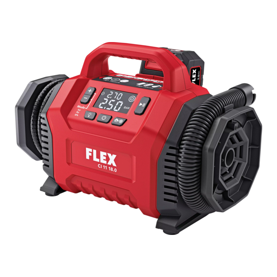
CI 11 18.0
Advertisement
Table of Contents

Related Manuals for Flex CI 11 18.0


Summary of Contents for Flex CI 11 18.0
- Page 1 CI 11 18.0 Faults which impair safety must be repaired Symbols used in this manual immediately. Intended use WARNING! The Dual function inflator is designed Denotes impending danger. Non-observance – for commercial use in industry and trade, of this warning may result in death or –...
-
Page 2: Noise And Vibration
SKIL factory poorly maintained, the vibration emission service center or authorized FLEX service may differ. This may significantly increase the station. Following this rule will reduce the exposure level over the total working period. -
Page 3: Inserting/Replacing The Battery
CI 11 18.0 NOTE 18V Flex Lithium Battery Rated The batteries are not fully charged on Pack or 12V voltage delivery. Prior to initial operation, charge the Vehicle Power batteries fully. Refer to the charger operating Maximum air 11 BAR / 1100 kPa /160 PSI manual. - Page 4 CI 11 18.0 ■ Push the air chuck (12) down so that the attach the slots in the hose to the pins (26), threaded section of the valve stem is inside then turn the hose counter clockwise until the air chuck it locks in place ■...
-
Page 5: Maintenance And Care
■ Regularly blow out the housing interior 2006/42/EC, 2011/65/EU. and motor with dry compressed air. Responsible for technical documents: FLEX-Elektrowerkzeuge GmbH, R & D Spare parts and accessories Bahnhofstrasse 15, D-71711 Steinheim/Murr For other accessories, see the manufacturer’s catalogues. Exploded drawings and spare- part lists can be found on our homepage: www.flex-tools.com... -
Page 6: Exemption From Liability
BS EN 55014-2:2015, Place of declaration: Steinheim, Germany. Responsible person: P P eter Lameli, Technical Director – FLEX-Elektrowerkzeuge GmbH Contact details for Great Britain: FLEX Power Tools Limited, Unit 8 Anglo Office Park, Lincoln Road, HP 12, 3RH Buckinghamshire, United Kingdom.
Need help?
Do you have a question about the CI 11 18.0 and is the answer not in the manual?
Questions and answers