Table of Contents
Advertisement
Quick Links
A3500
ANALOGUE CATEGORY P THERMAL DETEC-
TOR - ALTAIR SERIES
GENERAL DESCRIPTION
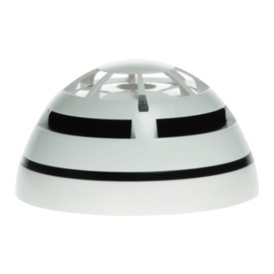
This type of detector (figure 1) continuously samples the temperature variation in the protected
area to provide the earliest warning of fire, offering, at the same time, a high level of false alarm
rejection.
These detectors are designed for an open area protection and must only be connected to control
panels that use the Altair analogue-intelligent addressable communication protocol for monitoring
and control, providing high rates of information exchange and fast and secure responses.
Note: Before installing this device please thoroughly read this leaflet and refer to the applicable
European Standards and National Codes of Practice (e.g. BS5839-1:2002 for UK) for guidance on
location, spacing and acceptable use. Also seek guidance from the compatible control panel
instructions to ensure appropriate design criteria and configuration specifications are followed.
INSTALLATION
For the installation to the ceiling, the detector must be mounted only on the compatible adaptor bases listed in the "TECHNICAL
SPECIFICATIONS" table. Refer to the specific base's literature for further details.
WIRING
After having installed the base to the ceiling, wiring has to be carried out in order to connect the base to the analogue loop and, so, to
the installation.
Analogue loop wires must be correctly connected to the base's terminals: check the performed wiring by referring to the figure 2
diagram.
LOOP IN (+)
LOOP IN (-)
ARGUS SECURITY S.R.L. - Via del Canneto, 14 - 34015 - Muggia (TS) - Italy
G 213009
LOOP OUT (+)
SHIELD
LOOP OUT (-)
Figure 2
www.argussecurity.it
REMOTE OUTPUT CAPABILITY
Remote output capability is available as a standard feature, so a
remote indication lamp or a compatible platform sounder (check
power requirements and loop drive limits) may be wired to the
base terminals (Figure 3).
928a/02
If other equipment is connected to the remote output, its
supply current must be eventually limited by using an ade-
quate resistor. Consult the TECHNICAL SPECIFICATIONS
table and assess the external device current absorption's
value.
SHORT CIRCUIT ISOLATORS
The detector is equipped with bi-directional short-circuit isolators
to help protect against wiring faults that may otherwise result in
loop failure. In the event of a short circuit isolators either side
should open to maintain most functions.
Normal operation can be restored after the fault has been correct-
Figure 1
ed.
DEVICE PROGRAMMING - ADDRESS SETTING
Detectors can be addressed using a special hand-held program-
ming unit or they can be automatically addressed from the control
panel (if this feature exists for the model used) after they have
been installed.
Addresses may be selected from a range from 1 to 240, although,
of course, each device on the loop must have a unique address
DEVICE PROGRAMMING - THERMAL SENSITIVITY SETTING
A choice of two thermal sensitivity levels is available; these two
levels correspond to a Rate Of Rise (ROR) A1R category (most
sensitive) and to a category BS (least sensitive), according to the EN 54 part 5
European normative.
Sensitivity level can be selected through a hand-held programming unit or, if such
feature is provided, directly through the control panel.
DETECTOR PLACEMENT
1) Position the detector centrally on its adaptor base ensuring it is level.
2) Rotate clockwise applying gentle pressure. The detector will drop into its keyed
location.
3) Continue to rotate clockwise a few degrees until the detector has fully engaged in
the adaptor base.
4) When the detector is firmly engaged, check the alignment of the raised reference
marks on the detector and on the base (figure 5).
IMPORTANT NOTES ON DETECTORS PLACEMENT
Disconnect loop power before installing the detector.
Dust covers help to protect the devices during shipping and when first installed.
They are not intended to provide complete protection against contamination, therefore,
detectors should be removed before construction, major re-decoration or other dust
producing work is started. Dust covers must be removed before the system can be made
operational.
info@argussecurity.it
Figure 3
REMOTE
REMOTE
ALARM (-)
ALARM (+)
Figure 4
Figure 5
L20-A3500-0001 (vA.5)
Advertisement
Table of Contents

Subscribe to Our Youtube Channel
Related Manuals for Argus Security A3500


Summary of Contents for Argus Security A3500
- Page 1 Dust covers must be removed before the system can be made operational. Figure 2 Figure 5 ARGUS SECURITY S.R.L. - Via del Canneto, 14 - 34015 - Muggia (TS) - Italy www.argussecurity.it info@argussecurity.it L20-A3500-0001 (vA.5)
- Page 2 Product must be returned via your authorized supplier for repair or replace- Figure 10 ment together with full information on any problem identified. Category A1R and BS (category P) ARGUS SECURITY S.R.L. - Via del Canneto, 14 - 34015 - Muggia (TS) - Italy www.argussecurity.it info@argussecurity.it L20-A3500-0001 (vA.5)
Need help?
Do you have a question about the A3500 and is the answer not in the manual?
Questions and answers