Table of Contents
Advertisement
Quick Links
INSTALLATION &
OPERATING INSTRUCTIONS
Instructions and notes for installation and operation
3T-MOTORS Radio shutter / awning motors
with mechanical limit switches
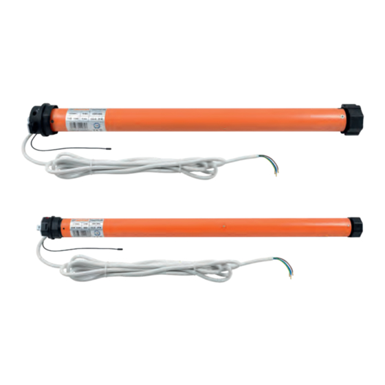
Motor type 3T45-R
Motor type 3T35-R
(For shafts from 60 mm)
(For shafts from 40 mm)
3T45-10R
3T35-10R
3T45-20R
3T35-13R
3T45-30R
3T45-40R
3T45-50R
Attention:
It is important for the safety of persons
to follow these instructions.
Keep these instructions for future reference.
www.3t-components.de
|
WEEE-Reg.-Nr.: DE 77028333
INTELLIGENT
DRIVES &
CONTROLS
FOR SHUTTERS
AND AWNINGS
Smart Home Ready with everHome
Control via smart phone, tablet, PC or via
voice commands with Alexa or Google Assistant
Advertisement
Table of Contents

Related Manuals for 3T-Components 3T-MOTORS 3T35-R


Summary of Contents for 3T-Components 3T-MOTORS 3T35-R
- Page 1 (For shafts from 60 mm) (For shafts from 40 mm) 3T45-10R 3T35-10R 3T45-20R 3T35-13R 3T45-30R 3T45-40R 3T45-50R Attention: It is important for the safety of persons to follow these instructions. Keep these instructions for future reference. www.3t-components.de WEEE-Reg.-Nr.: DE 77028333...
-
Page 2: Table Of Contents
Unless expressly indicated otherwise, the copyright is held by 3T-Components GmbH & Co. KG. Please ask us if you wish to use the contents of this document. 3T-MOTORS Radio tubular motors | Table of contents... -
Page 3: Guideline / Determine Torque
GUIDELINE With this guide, you can determine the ideal torque in Newton meters (Nm) for the shutter motor. DETERMINE WEIGHT ROLLER SHUTTER 1.) Determine roller shutter area Width (Height + 150 mm) x Width = Roller shutter area (m²) 2.) Determine weight roller shutter material Material kg / m²... -
Page 4: Safety Instructions
SAFETY INSTRUCTIONS Please read these important safety instructions before commissioning! Incorrect installation can cause serious personal injury and damage to property. The warranty claim expires in case of non-observance of this user information with all contained notes and regulations. In case of non-observance of these instructions, the manufacturer or supplier shall not be liable for any personal injury or property damage incurred. GENERAL SAFETY INSTRUCTIONS WARNING: Important safety instructions. -
Page 5: Function Overview
FUNCTION OVERVIEW SCOPE OF DELIVERY – MOTOR TYPE 3T45-R SCOPE OF DELIVERY – MOTOR TYPE 3T35-R Motor Motor Limit switch adapter Limit switch adapter Shaft adapter Shaft adapter Connection cable 3 meters Connection cable 3 meters Adjustment pin Adjustment pin Universal bearing &... -
Page 6: Installation Notes
INSTALLATION NOTES Before installation, all non-essential electrical wiring must be removed, all mechanisms that are not necessary for motorized operation must be deactivated. Do not expose the tubular motor to crushing, impact, falling or contact with any liquids. • Do not punch holes in the entire length of the tube (motor casing) or attach screws to it. Please use suitable suspension springs to fasten the roller shutter curtain to the roller shutter shaft. -
Page 7: Installation Instructions
INSTALLATION INSTRUCTIONS Please note: The motor can be installed on the right-hand side as well as on the left-hand side. • If the direction of rotation is reversed, please exchange the wires for the up and down direction. The setting of the end positions is only possible in the installed state (motor in shutter shaft). •... - Page 8 INSTALLATION INSTRUCTIONS Motor type 3T45-R Motor type 3T35-R Installation with universal bearing or cover cap bearing Installation with universal bearing or clip bearing Universal bearing Cover cap bearing Universal bearing clip bearing Installation with universal bearing: Installation with universal bearing: Push the motor with the square into the opening of the bearing Push the motor with the square into the opening of the bearing •...
-
Page 9: Remove Shutter Shaft
INSTALLATION INSTRUCTIONS Remove shutter shaft: Lower the roller shutter. • Open the cover of the roller shutter box. • Release the suspension springs from the roller shutter shaft. • Lift roller shutter shaft incl. ball bearing out of the holder. •... -
Page 10: Shutter Motor Wiring
INSTALLATION INSTRUCTIONS On the opposite side of the motor, push the roller capsule out of the roller shutter shaft until it fits into the ball bearing inserted in the wall bearing. • Fix roller capsule to roller shutter shaft with self-tapping screw. Position the screw at a punched hole. This prevents the screw from slipping. •... - Page 11 INSTALLATION INSTRUCTIONS The straight up and down arrows indicate the direction of rotation of the motor and shaft and thus show you for which end position the limit switch screw next to it is responsible. Depending on whether the direction of rotation leads to unrolling or rolling up of the roller shutter, the limit switch screw is responsible for the lower or upper end position (unrolling >...
-
Page 12: Mounting Instructions For Motor Type 3T35-R
INSTALLATION INSTRUCTIONS If the shaft has to be turned a little to hook in the suspension springs, use the adjustment pin on the • limit switch screw for the lower end position in the PLUS direction. This causes the motor to turn the shaft stepwise. -
Page 13: Installation Radio Awning Motor
INSTALLATION INSTRUCTIONS INSTALLATION RADIO AWNING MOTOR Preparation: Attention: Screw in awning & secure with straps or ropes. • Awning arms are under strong tension! Remove awning from wall bracket & place on safe surface. • Prepare motor for installation: Slide limit switch adapter flush against motor head. >... -
Page 14: Radio Awning Motor Wiring
INSTALLATION INSTRUCTIONS Slide the side bearing with universal bearing onto the support tube & fasten. > fig. 3.9 • Ensure that the motor square spigot is properly engaged in the universal bearing. > fig. 3.10 • Secure the motor square spigot with the supplied cotter pin. >... -
Page 15: Setting The End Positions
INSTALLATION INSTRUCTIONS Setting the end positions: Explanation of the limit switch screws There are 2 limit switch screws on the motor head. One limit switch screw is responsible for the „EXTEND” position, the other for the „RETURN” position. By turning the limit switch screws with the adjustment pin, the positions of the limit switch can be adjusted. A detailed description of the limit switch screws and the markings on the motor head can be found on page 11. -
Page 16: Programming Radio Transmitter
PROGRAMMING RADIO TRANSMITTER Important when teaching, changing or deleting transmitters: Only one relevant motor may be switched to voltage! Several radio motors or radio receivers can be programmed to form a group with the same transmission channel. For multi-channel transmitters, channel by channel must be taught or transferred. Pairing handheld transmitters After switching on the power supply, programming (pressing the buttons) must be carried out within 10 seconds. -
Page 17: Delete Handheld Transmitter
PROGRAMMING RADIO TRANSMITTER Delete handheld transmitter: Programming (pressing the buttons) must be carried out within 10 seconds. Otherwise the motor returns to its original state. Attention! Deleting the handheld transmitter deletes all paired transmitters on the radio motor. Beep while Beep while pressing pressing... -
Page 18: Troubleshooting
TROUBLESHOOTING WHAT TO DO WHEN ..the motor does not run? Mains voltage is missing. • Transmitter was not paired correctly. • ... the motor is running in the wrong direction? Change the direction of rotation by pairing the transmitter again (see Change direction of rotation of radio motor > page 16). •... -
Page 19: 3T Components Gmbh & Co. Kg
EU Konformitätserklärung Wir, die Firma 3T Components GmbH & Co. KG Grete-Schickedanz-Str. 5 55545 Bad Kreuznach Deutschland erklären in alleiniger Verantwortung, dass das weiter unten genannte Produkt Geräteart: Rohrmotor mit integriertem Funkempfänger 433MHz Modell Artikelnummer 3T35-10R 3T35-13R 3T45-10R 3T45-20R 3T45-30R 3T45-40R 3T45-50R die grundlegenden Anforderungen der aufgeführten EG/EU-Richtlinien erfüllt:... -
Page 20: D-55545 Bad Kreuznach
Social Media Links Info, news and tips on roller shutters, awnings, smart home and more: www.facebook.com/3TComponents bit.ly/youtube-3TComponents www.instagram.com/3tcomponents twitter.com/3TComponents 3T-Components GmbH & Co. KG Grete-Schickedanz-Straße 5 D-55545 Bad Kreuznach Email: info@3t-components.de Tel: +49 (0)671 887 673-0 Fax: +49 (0)671 887 673-99 www.3t-components.de...
Need help?
Do you have a question about the 3T-MOTORS 3T35-R and is the answer not in the manual?
Questions and answers