Table of Contents
Advertisement
Quick Links
Advertisement
Table of Contents

Related Manuals for MiTAC TYAN FA100-B7118


Summary of Contents for MiTAC TYAN FA100-B7118
- Page 1 FA100-B7118 Service Engineer’s Manual...
- Page 2 MITAC COMPUTING TECHNOLOGY CORPORATION. Version 1.0 Disclaimer Information contained in this document is furnished by MiTAC Computer Corporation and has been reviewed for accuracy and reliability prior to printing. ® TYAN assumes no liability whatsoever, and disclaims any express or implied ®...
- Page 3 FCC Declaration Notice for the USA Compliance Information Statement (Declaration of Conformity Procedure) DoC FCC Part 15: This device complies with part 15 of the FCC Rules. This device complies with Part 15 of the FCC Rules. Operation is subject to the following conditions: ‧This device may not cause harmful interference.
- Page 4 Warning This equipment is compliant with Class A of CISPR 32. In a residential environment this equipment may cause radio interference. CAUTION Lithium battery included with this board. Do not puncture, mutilate, or dispose of battery in fire. There will be danger of explosion if battery is incorrectly replaced. Replace only with the same or equivalent type recommended by manufacturer.
- Page 5 About this Manual This Manual is intended for trained service technician/personnel with hardware knowledge of personal computers. It is aimed to provide you with instructions on installing your TYAN FA100-B7118. How this guide is organized This guide contains the following parts:...
- Page 6 Safety and Compliance Information Before installing and using TYAN FA100-B7118, take note of the following precautions: ·Read all instructions carefully. ·Do not place the unit on an unstable surface, cart, or stand. ·Do not block the slots and opening on the unit, which are provided for ventilation.
- Page 7 Safety Information Retain and follow all product safety and operating instructions provided with your equipment. In the event of a conflict between the instructions in this guide and the instructions in equipment documentation, follow the guidelines in the equipment documentation. Observe all warnings on the product and in the operating instructions.
- Page 8 General Precautions · Follow all caution and warning instructions marked on the equipment and explained in the accompanying equipment documentation. Machine Room Environment · Make sure that the area in which you install the system is properly ventilated and climate-controlled. ·...
- Page 9 · Make sure the rack is properly secured to the floor or ceiling. · Make sure the stabilizing feet are attached to the rack if it is a single-rack installation. · Make sure racks are coupled together if it is a multiple-rack installation. ·...
- Page 10 Equipment Power Cords · Use only the power cords and power supply units provided with your system. The system might have one or more power cords. · Plug the power cord into a grounded (earthed) electrical outlet that is easily accessible at all times.
- Page 11 Equipment Repairs and Servicing · The installation of internal options and routine maintenance and service of this product should be performed by trained service technicians/personnel who are knowledgeable about the procedures, precautions, and hazards associated with equipment containing hazardous energy levels. ·...
-
Page 12: Table Of Contents
Table of Contents Chapter 1: Overview ..............14 About the TYAN FA100-B7118 ........... 14 Features................15 Standard Parts List .............. 18 1.3.1 Box Contents ..............18 1.3.2 Accessories ..............18 About the Product ..............19 1.4.1 System Front View ............19 1.4.2... - Page 13 Chapter 4: Motherboard Information .......... 68 Board Image ................ 69 Mainboard Mechanical Drawing .......... 69 Block Diagram ..............70 Board Parts, Jumpers and Connectors ....... 71 Chapter 5: BIOS Setup ..............76 About the BIOS ..............76 Main Menu ................78 Advanced Menu ..............
-
Page 14: Chapter 1: Overview
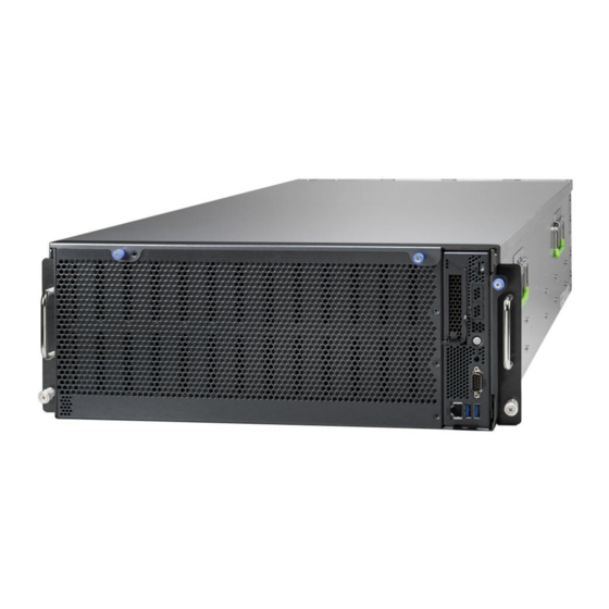
Chapter 1: Overview About the TYAN FA100-B7118 ® Congratulations on your purchase of the TYAN FA100-B7118, a highly optimized rack-mountable 4U barebone system. FA100-B7118 is designed to support Dual ® ® Intel Xeon Scalable Processors and Up to 512GB RDIMM/ 1,024GB LRDIMM/... -
Page 15: Features
Features B7118F100V100HR Specifications Form Factor 4U Rackmount Chassis Model FA100 39.96" x 17.13" x 6.86" (1015 x 435 Dimension (D x W x H) x 174mm) System Motherboard S7118GMR Gross Weight 72 kg (158.7 lbs) Net weight 45 kg (99.2 lbs) Buttons (1) PWR w/ LED, (1) UID Front Panel... - Page 16 Chipset Intel C621 Supported DIMM (8)+(8) DIMM slots DDR4 RDIMM/RDIMM DIMM Type / Speed 3DS/LRDIMM/LRDIMM 3DS 2666 Up to 512GB RDIMM/ 1,024GB Memory LRDIMM/ 2,048GB LRDIMM 3DS Capacity *Follow latest Intel DDR4 Memory Memory channel 6 Channels per CPU Memory voltage 1.2V (1) PCI-E Gen3 x16 slot, (1) OCP Expansion Slots...
- Page 17 Onboard Chipset Onboard Aspeed AST2500 IPMI 2.0 compliant baseboard management controller (BMC), AST2500 iKVM Supports storage over IP and Feature Server Management remote platform-flash, USB 2.0 virtual hub 24-bit high quality video AST2500 IPMI compression, 10/100/1000 Mb/s Feature MAC interface Brand / ROM size AMI, 32MB Hardware Monitor, SMBIOS...
-
Page 18: Standard Parts List
Standard Parts List This section describes FA100-B7118 package contents and accessories. Open the box carefully and ensure that all components are present and undamaged. The product should arrive packaged as illustrated below. 1.3.1 Box Contents FA100-B7118 Chassis Kit 4U chassis ... -
Page 19: About The Product
About the Product The following views show you the product. 1.4.1 System Front View http://www.tyan.com... -
Page 20: Led Definitions
1.4.2 LED Definitions 10Gbps LAN Port LAN Indication 10/100/1000 Mbps LAN Link/Activity LED Scheme Left LED Right LED (Link/Activity) (Speed) No Link Solid Green Solid Green Link 100 Mbps Blinking Green Solid Green Active Solid Green Solid Amber Link 1000 Mbps Blinking Green Solid Amber Active... - Page 21 PSU LED Definitions Dual-color Power Supply Condition Green LED Amber LED No AC power to all power supplies AMBER Power supply critical event causing a shutdown failure, OCP, OVP, Fan Fail, OTP, UVP Power supply warning events where Blink AMBER the power supply continues to operate;...
-
Page 22: Internal View
1.4.4 Internal View Explanation Compute Blade, with pre-install S7118GMR MB and M2091-R Riser Card Expander Module, with pre-install (1) M7118F100-EXP12-100 SAS Expander Backplane (1) M7118-3008-8I SAS IOC Mezzanine card System Fan Modules (with install 8 fans) 1600W Two Power Supply with pre-install (1) M1621F100-PDB Power Distribution Board (100) 3.5”/2.5”... -
Page 23: Mb Module Internal View
1.4.5 MB Module Internal View Explanation PCIE Module CPU Sockets Memory Slots OCP_LAN2/OCP Slot(B) OCP_LAN1/OCP Slot(A) PCIE 3.0 Slot x16 http://www.tyan.com... -
Page 24: Chapter 2: Setting Up
Chapter 2: Setting Up 2.0.1 Before you Begin This chapter explains how to install the CPUs, CPU heatsinks, memory modules, and hard drives. Instructions on inserting add on cards are also given. 2.0.2 Work Area Make sure you have a stable, clean working environment. Dust and dirt can get into components and cause malfunctions. -
Page 25: Precautions
2.0.4 Precautions Components and electronic circuit boards can be damaged by discharges of static electricity. Working on a system that is connected to a power supply can be extremely dangerous. Follow the guidelines below to avoid damage to FA100-B7118 or injury to yourself. ... -
Page 26: 2.1 Installing Motherboard Components
2.1 Installing Motherboard Components This section describes how to install components on to the motherboard, including CPUs, memory modules and Add-on cards. 2.1.1 Removing the Chassis Cover Follow these instructions to remove FA100-B7118 chassis cover. Remove the screw from the top cover. Release the two thumb screws on the front side as illustrated in the image. - Page 27 Pinch the two thumb screw to pull the cover in the direction of the arrow to remove the top cover. Unscrew the top cover and release the latches to remove the top cover from http://www.tyan.com...
- Page 28 2.1.2 Release the Compute Blade Release the thumb screw on the left side as illustrated in the image. Release the thumb screw on the left side as illustrated in the image. Pull out the MB Module in the direction of arrow as illustrated in the image. http://www.tyan.com...
-
Page 29: Installing The Cpu And Heat Sink
2.1.2 Installing the CPU and Heat sink Follow the steps below on installing CPUs and CPU heat sinks. Locate the CPU socket. Started at CPU0 and remove the CPU protection cap. Put the Narrow-Fabric processor on the Carrier hook clips. http://www.tyan.com... - Page 30 Align and install the processor on the carrier. Carefully flip the heatsink. Then install the carrier assembly on the bottom of the heatsink and make sure Carrier hook clips is stuck in the heatsink. Align the heatsink on the CPU socket by the guide pins and make sure the gold arrow is located in the correct direction.
- Page 31 FA100-B7118 has equipped with two kinds of heatsinks on the CPU socket. One is made of copper and the other is made of aluminum. To secure the heatsink, use a T30 Security Torx to tighten the screws in a sequential order (1->2 -> 3 -> 4). When disassembling the heatsink, loosen the screws in reverse order (4 ->...
-
Page 32: Installing The Memory
2.1.3 Installing the Memory Follow these instructions to install the memory modules onto the motherboard. Press the memory slot locking levers in the direction of the arrows as shown in the following illustration. 2. Align the memory module with the slot. When inserted properly, the memory slot locking levers lock automatically onto the indentations at the ends of the module. -
Page 33: Memory
2.1.4 Memory Before installing memory, ensure that the memory you have is compatible with the motherboard and processor. Check the TYAN Web site at http://www.tyan.com details of the type of memory recommended for your motherboard. Supports up to (8+8) R-DDR-4 up to 2666MHz memory ... - Page 34 Recommended Memory Population Table Quantity of Dual CPU Installed memory installed (CPU0 and CPU1) √ √ √ √ √ √ √ √ P0_MC0_DIM_CH_A0 √ √ P0_MC0_DIM_CH_A1 √ √ √ √ √ √ √ P0_MC0_DIM_CH_B0 √ √ √ √ √ P0_MC0_DIM_CH_C0 √...
-
Page 35: Installing Expansion Cards
2.1.5 Installing Expansion Cards TheFA100-B7118 has one preinstalled M2091-R riser card. You can install an Add-On card into the expansion slot which is available with riser card. The following instructions are for Add-On card installation. You may refer to the procedures below for the installation. 1. - Page 36 3. Insert the Add-On card to the M2091-R riser card. 4. Reinstall the riser bracket to the chassis and secure 3 screws. http://www.tyan.com...
- Page 37 http://www.tyan.com...
-
Page 38: Installing Hard Drives
2.1.6 Installing Hard Drives The FA100-B7118 supports 100 3.5”/2.5” Hard Drives. Follow these instructions to install a hard drive. Installing 3.5” HDD Press Locking lever to release the 3.5”/2.5” HDD tray. Pull the 3.5”/2.5” HDD tray out of the chassis. 3. - Page 39 4. Reinsert the HDD tray into the chassis. http://www.tyan.com...
- Page 40 Installing 2.5” HDD Press Locking lever to release the 3.5”/2.5” HDD tray. Pull the 3.5”/2.5” HDD tray out of the chassis. Remove the screw in the red circle. http://www.tyan.com...
- Page 41 Place a 3.5” hard drive into the drive tray. Secure the 2.5” hard drive onto the drive tray. http://www.tyan.com...
- Page 42 Reinsert the HDD tray into the chassis. http://www.tyan.com...
-
Page 43: Rack Mounting
Sliding Rail Kit (inner rail) NOTE: Before mounting the TYAN FA100-B7118 in a rack, ensure that the right or left inner rail have been installed correctly. If not, the power cable module cannot be installed on the chassis kit. -
Page 44: Installing The Server In A Rack
2.2.1 Installing the Server in a Rack Follow these instructions to mount the TYAN FA100-B7118 into an industry standard 19" rack. NOTE: Before mounting the TYAN FA100-B7118 in a rack, ensure that all internal components have been installed and that the unit has been fully tested. However, to make the installation easier, we suggest that you remove all HDD trays before you insert the chassis into the rack. - Page 45 Rack Mounting the Server Pull out the outer rail to the full length. Lift the unit and then insert the inner slide rails into the Outer rails. Secure the two rotary screws on the mounting ears of the unit to the rack. http://www.tyan.com...
-
Page 46: Chapter 3: Replacing Pre-Installed Components
Chapter 3: Replacing Pre-Installed Components Introduction This chapter explains how to replace the pre-installed components, including the S7118GMR Motherboard, M2091-R PCI-E Riser Board, M1289F100-BP12-61/ M1288F100-BP12-39 HDD Backplane Board, M7118F100-EXP12-10 Expander Backplane Board, M7118-3008-8I SAS IOC Mezzanine Card,M1621F100-PDB Power Distribution Board, System Fan and Power Supply, etc. Disassembly Flowchart The following flowchart outlines the disassembly procedure. -
Page 47: Removing The Cover
Removing the Cover Before replacing any parts you must remove the chassis cover. Follow Chapter 2.1.1 to remove the cover of FA100-B7118. Replacing the Power Supply To replace the power supply follow these instructions. Press the tab as in the diagram from down to up. Free the power from the power socket. - Page 48 Replace a new single power and reinsert it into the power socket following the above steps in reverse. http://www.tyan.com...
-
Page 49: Replacing Power Distribution Board
Replacing Power Distribution Board Follow these instructions to replace the M1621F100-PDB Power Distribution Board. 1. Rotate to release the M1621F100-PDB Power Distribution Board. 2. Remove the one screw on both sides. 4. Follow the steps described earlier in reverse order to reinstall the power distribution board into the chassis. -
Page 50: Power Distribution Board Features
3.5.1 Power Distribution Board Features Form Factor 158mmx123mm,T=2.4mm Connectors (3) 12V/5V Power Connectors 3.5.2 Power Distribution Board Pin Definition ATX Power Connector: J1 Signal Signal +12V_IN +12V_IN +12V_IN +12V_IN +12V_IN +12V_IN +12V_IN +12V_IN +12V_IN +12V_IN +12V_IN +12V_IN +12V_IN +12V_IN http://www.tyan.com... - Page 51 24-Pin ATX Power Connector: (PSU1 and PSU2) Signal Signal +12V_IN +12V_IN +12V_IN +12V_IN +12V_IN +12V_IN +12V_IN +12V_IN +12V_IN +12V_IN +12V_IN +12V_IN +12V_IN +12V_IN +12V_IN +12V_IN +12V_IN +12V_IN PSU1_SDA PSU1_A0 PSU1_SCL PSU1_A1 PSU1_PSON_N +12VSB PSU1_ALERT PSU1SMART_ON PSU1_RETURN_S PSU1_12VLS PSU1_12VS+ PSU1_PRESENT_N PSU1_PWOK PSU1_PS_KILL http://www.tyan.com...
-
Page 52: Replacing Expansion Cards
Replacing Expansion Cards The FA100-B7118 has one preinstalled M2091-R riser card. The following instructions are for expansion card uninstallation. You may refer to the procedures below for the uninstallation. Remove the two screws secured of PCI-E bracket. Remove the screw to release the M2091-R riser card. 3.6.1 Riser card Feature M2091-R riser card... -
Page 53: Replacing The System Fan
Replacing the System Fan Follow these instructions to replace a new fan. 1. Press the tab as in the image. Pull out the system fan in the direction to replace a new one. http://www.tyan.com... - Page 54 3. Push to detach the fan mask. 4. Push the latch in the direction as the arrow shown to release the fan from the iron holder. Push to detach the rubber screw for the system fan. http://www.tyan.com...
- Page 55 6. Remove the three screws and rubber screw from the other side. Push the rubber screws to pull them out as illustrated in the image. 8. Detach all the four rubber screws and fan cage. http://www.tyan.com...
- Page 56 Replace a new system fan and follow the procedure mentioned in the reverse order to reinstall it into the fan cage. http://www.tyan.com...
-
Page 57: Replacing Expander Backplane Board
Replacing Expander Backplane Board Follow these instructions to replace the M7118F100-EXP12-10 Expander Backplane Board and M7118-3008-8I SAS IOC Mezzanine Card. Press the tab as in the image to release the expander backplane board. Pinch the tab as in the image to pull out the expander backplane board. Remove the 4 screws to release the M7118-3008-8I SAS IOC Mezzanine... - Page 58 Remove the 7 screws to release the M7118F100-EXP12-10 Expander Backplane Board. http://www.tyan.com...
- Page 59 3.8.1 SAS IOC Mezzanine Card Features Front View Rear View Form Factor 115x95mm (2) OCP Connector(J1/J2) Connectors (2) LSI3008 X2 http://www.tyan.com...
- Page 60 3.8.2 Expander Backplane Board Features 328mm*138mm,T=2.3mm Form Factor 6x SATA Connector(J22,J23,J24,J25,J26,J27) 1x PCIe Connector(J6) 1x JTAG Connector(JTAG1) Connectors 6x PWR Connector(PWR1/PWR2/ PWR4/PWR5/PWR7) 2x OCP Connector(J4/J5) http://www.tyan.com...
-
Page 61: Replacing Hdd Backplane Board
Replacing HDD Backplane Board Follow these instructions to replace the M1289F100-BP12-61/ M1288F100-BP12-39 HDD Backplane Board. Remove the one screw on the left side. Remove the one screw on the rear side. Removing the one screw on the front side. http://www.tyan.com... - Page 62 Remove the 27 pcs screws to release the HDD backplane from the chassis. 5. Lift up the HDD bracket. 6. Unscrew the 2 screws. http://www.tyan.com...
- Page 63 Lift the Fan power bracket. Lift the Fan power bracket. Disconnect the rear UID LED cable. http://www.tyan.com...
- Page 64 10. Unscrew the two thumb screws. 11. Take out the HDD backplane board. http://www.tyan.com...
-
Page 65: Hdd Back Plane Board Features
3.9.1 HDD Back Plane Board Features Form Factor: 558mm*415mm *3.5mm Thickness 3.5mm Layer: 12 layers Integrated I/O 4x Cooledge Connector 39x HDD Connectors(HDD1~HDD39) http://www.tyan.com... - Page 66 Form Factor: 558mm*415mm *3.5mm Thickness 3.5mm Layer: 12 layers Integrated I/O 4x Cooledge Connector 6x SAS to Expander Connector (J22/J23/J24/J25/J26/J27) 4x FAN Connector 1x 92P PSU Connector(J11) 4x 4P*4 PSU Connector J30/J32 (VCC5 Power Connector) J31/J39 VCC12 Power Connector) 61x HDD Connectors(HDD40~HDD99)
-
Page 67: Replacing The Motherboard
3.10 Replacing the Motherboard After removing all of the aforementioned cables, follow these instructions to remove the motherboard from the chassis. 1. According to the screw location picture to unscrew to replace a new motherboard as illustrated. There are totally ten screws. http://www.tyan.com... -
Page 68: Chapter 4: Motherboard Information
Unplug the power from your computer power supply and then touch a safely grounded object to release static charge (i.e. power supply case). For the safest conditions, MiTAC recommends wearing a static safety wrist strap. (2) Hold the motherboard by its edges and do not touch the bottom of the board, or flex the board in any way. -
Page 69: Board Image
Board Image S7118GMR Motherboard This picture is representative of the latest board revision available at the time of publishing. The board you receive may not look exactly like the above picture. Mainboard Mechanical Drawing http://www.tyan.com... -
Page 70: Block Diagram
Block Diagram S7118 Block Diagram http://www.tyan.com... -
Page 71: Board Parts, Jumpers And Connectors
Board Parts, Jumpers and Connectors http://www.tyan.com... - Page 72 MotherBoard Jumpers&Connectors Connectors RJ45 LAN Port #1 SD Card (J56) (LAN1)/USB 3.0 (USB3_IPMI_LAN1) COM1 Port Board to Expender (COM_11) Connector (J55) ID LED Button Power Connector (PWR1) (IDLED_BTN1) Power Button/LED Power Connector (PWR2) (J7) TYAN Module Header ID LED (ID_LED1) (DBG_HD1) Jumpers ME Firmware Update...
- Page 73 DBG_HD1: TYAN Module Header Signal Signal P3V3 FRAME_N LAD0 LAD1 PLT_RST_N LAD2 LAD3 CLK_33M DBG_SERIRQ DBG_PRES_N VCC3_AUX TPM_ADDR_MB PCH_TPM_PP_EN 3PHD_2: ME Recovery Mode Jumper Signal Signal FM_ME_RCVR_N Pin 1-2 Closed: Normal Mode (Default) Pin 2-3 Closed: ME Recovery Mode ID LED_BTN1: ID LED Button Header Signal FP_IDLED_BTN_N Power_BTN1: ID LED Button Header...
- Page 74 PSU1/2: ATX 24-pin System Power Connector Signal Signal P12V_IN P12V_IN P12V_IN P12V_IN P12V_IN P12V_IN P12V_IN P12V_IN P12V_IN P12V_IN P12V_IN P12V_IN LED1 / IDLED_BTN: ID LED and Button Signal P3V3_AUX ID_SW_L State Color Description Blue System identified System not identified NOTE: The ID LED can be activated remotely using IPMI.
- Page 75 Some chassis include plastic studs instead of metal. Although the plastic studs are usable, MiTAC recommends using metal studs with screws that will fasten the motherboard more securely in place. Below is a chart detailing what the most common motherboard studs look like and how they should be installed.
-
Page 76: Chapter 5: Bios Setup
Chapter 5: BIOS Setup About the BIOS The BIOS is the basic input/output system, the firmware on the motherboard that enables your hardware to interface with your software. The BIOS determines what a computer can do without accessing programs from a disk. The BIOS contains all the code required to control the keyboard, display screen, disk drives, serial communications, and a number of miscellaneous functions. - Page 77 Chipset section unless you are absolutely sure of what you are doing. The Chipset defaults have been carefully chosen either by MiTAC or your system manufacturer for best performance and reliability. Even a seemingly small change to the Chipset setup options may cause the system to become unstable or unusable.
-
Page 78: Main Menu
Main Menu In this section, you can alter general features such as the date and time. Note that the options listed below are for options that can directly be changed within the Main Setup screen. BIOS Information It displays BIOS related information. Platform Information It displays Platform information. -
Page 79: Advanced Menu
Advanced Menu This section facilitates configuring advanced BIOS options for your system. iSCSI Configuration Configure the iSCSI parameters Intel® Virtual RAID on CPU This formset allows the user to manage Intel® Virtual RAID on CPU Trusted Computing Trusted Computing settings. ACPI Settings System ACPI Parameters. - Page 80 SIO Configuration SIO Configuration Option ROM Dispatch Policy Option ROM Dispatch Policy PCI Subsystem Settings PCI, PCI-X and PCI Express Settings Network Stack Configuration Network Stack Settings CSM Configuration CSM Configuration, Enable/Disable Option ROM execution setting, etc USB Configuration USB Configuration Parameters. Hardware Health Configuration Hardware Health Configuration NVDIMM ADR Configuration...
- Page 81 5.3.1 iSCSI Configuration iSCSI Name The worldwide unique name of iSCSI Initiator. Only IQN format is accepted. Range is from 4 to 223. http://www.tyan.com...
- Page 82 5.3.2 Intel(R) Virtual RAID on CPU Please follow the instructions to initiate the Intel Virtual RAID on CPU function. Step 1. Select Socket Configuration IIO Configuration Intel® VMD technology Intel® VMD for Volume Management Device on Socket 0 (for CPU0) / Socket 1 (for CPU1) ...
- Page 83 5.3.3 Trusted Computing Security Device support Enables or Disables BIOS support for security device. O.S. will not show Security Device. TCG EFI protocol and INT1A interface will not be available. Disabled / Enabled http://www.tyan.com...
- Page 84 5.3.4 ACPI Settings Enable ACPI Auto Configuration Enable or disable BIOS ACPI Auto Configuration. Disabled / Enabled Enable Hibernation Enables or disables System ability to Hibernate (OS/S4 Sleep State). This option may not be effective with some OS. Disabled / Enabled http://www.tyan.com...
- Page 85 5.3.5 Onboard Device Configuration NMI Button Enable or disable NMI button. Disabled / Enabled http://www.tyan.com...
- Page 86 5.3.6 S5 RTC Wake Setting http://www.tyan.com...
- Page 87 Wake system from S5 Enable or disable System wake on alarm event. Select Fixed time, system will wake on the hr ::min ::sec specified. Select Dynamic Time, System will wake on the current time+ increase minute(s) Disabled / Fixed Time / Dynamic Time NOTE: Submenu will appear when Wake system from S5 is not set to [Disabled].
- Page 88 5.3.7 Serial Port Console Redirection COM1/COM2 Console Redirection Console redirection enable or disable. Disabled / Enabled Serial Port for Out-Of-Band Management/Windows Emergency Services (EMS) Console Redirection Console redirection enable or disable. Disabled / Enabled Console Redirection Settings The settings specify how the host computer (which the user is using) will exchange data.
- Page 89 5.3.7.1 Console Redirection Settings Terminal Type Emulation: ANSI: Extended ASCII charset. VT100: ASCII charset. VT100+: Extends VT100 to support color function keys, etc. VT-UTF8: Uses UTF8 encoding to map Unicode chars onto 1 or more bytes. VT-UTF8 / VT100 / VT100+ / ANSI Bits per Second Select serial port transmission speed.
- Page 90 Stop Bits Stop bits indicate the end of a serial data packet. (A start bit indicates the beginning). The standard setting is 1 stop bit. Communication with slow devices may require more than 1 stop bit. 1 / 2 Flow Control Flow Control can prevent data loss from buffer overflow.
- Page 91 5.3.7.2 Console Redirection Settings Terminal Type Emulation: ANSI: Extended ASCII charset. VT100: ASCII charset. VT100+: Extends VT100 to support color function keys, etc. VT-UTF8: Uses UTF8 encoding to map Unicode chars onto 1 or more bytes. VT-UTF8 / VT100 / VT100+ / ANSI Bits per Second Select serial port transmission speed.
- Page 92 Stop Bits Stop bits indicate the end of a serial data packet. (A start bit indicates the beginning). The standard setting is 1 stop bit. Communication with slow devices may require more than 1 stop bit. 1 / 2 Flow Control Flow Control can prevent data loss from buffer overflow.
- Page 93 5.3.7.3 Legacy Serial Redirection Settings Legacy Serial Redirection Port Select a COM port to display redirection of Legacy, OS and Legacy OPROM Messages COM1 / COM2 http://www.tyan.com...
- Page 94 5.3.7.4 Serial Port for Out-Of-Band Management/Windows Emergency Services (EMS) Console Redirection Settings Out-of Band Mgmt Port Microsoft Windows Emergency Management Services (EMS) allows for remote management of a Windows Server OS through a serial port. COM1 / COM2 Terminal Type VT-UTF8 is the preferred terminal type for out-of-band management.
- Page 95 Data Bits / Parity / Stop Bits Read only. 5.3.8 SIO Configuration [* Active*] Serial Port 1 View and Set basic properties of the SIO logical device. Like IO base, IRQ Range, DMA Channel and Device Mode [* Active*] Serial Port 2 View and Set basic properties of the SIO logical device.
- Page 96 5.3.8.1 Serial Port 1/2 Configuration Use This Device Enable or Disable this Logical Device. Disabled / Enabled Possible Allows the user to change the device resource settings. New settings will be reflected on this setup page after system restarts. Use Automatic Settings / IO=3F8h;...
- Page 97 5.3.9 Option ROM Dispatch Policy Configuration Restore if Failure If system fails to boot and this option is set to ’Enabled’, software will reset settings of this page as well as CSM page to its default value automatically. Disabled / Enabled LSI SAS Card 1 Enable/Disable LSI SAS Card1, Enable Load Option ROM When Select Enabled, Disabled Load Option ROM when Select Disabled.
- Page 98 PCIE Slot: Empty Enable or Disable Option ROM execution for selected Slot. Disabled / Enabled 5.3.10 PCI Subsystem settings Above 4G Decoding Enables or Disables 64bit capable Devices to be decoded in Above 4G Address Space(Only if System supports 64 bit PCI decoding). Enabled / Disabled SR-IOV Support If system has SR-IOV capable PCIe Devices, this option Enables or Disables Single...
- Page 99 3.3.11 Network Stack Configuration Network Stack Enable / Disable UEFI Network Stack. Disabled / Enabled http://www.tyan.com...
- Page 100 5.3.12 CSM Configuration CSM support Enable/Disable CSM Support Enabled / Disabled Option ROM Messages Set display mode for Option ROM Force BIOS / Keep Current Boot option filter This option controls Legacy/UEFI ROMs priority UEFI and Legacy / Legacy only / UEFI only Network Controls the execution of UEFI and legacy PXE OpROM UEFI / legacy...
- Page 101 5.3.13 USB Configuration Legacy USB Support Enable legacy USB support. AUTO option disables legacy support if no USB devices are connected. DISABLE option will keep USB devices available only for EFI applications. Enabled / Disabled / Auto XHCI Hand-off This is a workaround for OSes without XHCI hand-off support. The XHCI ownership change should be claimed by XHCI driver.
- Page 102 USB transfer time-out The time-out value for Control, Bulk and Interrupt transfers. 20 sec / 10 sec / 5 sec / 1 sec Device reset time-out USB mass storage device Start Unit command time-out. 20 sec / 10 sec / 30 sec / 40 sec Device power-up delay Maximum time the device will take before it properly reports itself to the Host Controller.
- Page 103 5.3.14 Hardware Health Configuration Auto Fan Control Auto Fan Control help. Disabled / Enabled BMC Alert Beep Enable/Disable BMC Alert Beep. On / Off PMBus Support PMBus Support Disabled / Enabled Number of PSU Number of PSU 1 / 1+1 http://www.tyan.com...
- Page 104 5.3.14.1 Sensor Data Register Monitoring When you enter the Sensor Data Register Monitoring submenu, you will see the following dialog window pop out. Please wait 8~10 seconds. NOTE 1: SDR can not be modified. Read only. http://www.tyan.com...
- Page 105 http://www.tyan.com...
- Page 106 http://www.tyan.com...
- Page 107 5.3.15 NVDIMM ADR Configuration Assert ADR on Reset Assert ADR on Reset Disabled / Enabled Assert ADR on Shutdown Assert ADR on Shutdown Disabled / Enabled http://www.tyan.com...
-
Page 108: Platform Configuration Menu
Platform Configuration Menu PCH Configuration Displays and provides option to change the PCH Settings. Miscellaneous Configuration Miscellaneous Configuration Server ME Configuration Configure Server ME technology Parameters http://www.tyan.com... - Page 109 5.4.1 PCH Configuration PCI Express Configuration PCI Express Configuration settings PCH SATA Configuration SATA devices and settings PCH sSATA Configuration sSATA devices and settings USB Configuration USB Configuration Settings PCH DFX Configuration PCH DFX Configuration Options PCH state after G3 Select S0/S5 for ACPI state after a S3 S0 / S5 / Last State http://www.tyan.com...
- Page 110 OCULINK Configuration Select PCIe or SATA for OCULINK Configuration. When set to PCIe, it will detect as the PCIe OCULINK device, if set to SATA, it will detect as the SATA OCULINK device. PCIe / SATA 5.4.1.1 PCI Express Configuration PCI Express Root Port Control the PCI Express Root Port Disabled / Enabled...
- Page 111 PCIe Speed PCI Express Root Port Completion Timer TO settings Auto / Gen1 / Gen2 / Gen3 Max Payload Size PCIE Max Payload Size Selection. MPL 128B / MPL 256B 5.4.1.2 PCH SATA Configuration Submenu http://www.tyan.com...
- Page 112 http://www.tyan.com...
- Page 113 SATA Controller Enable or Disable SATA Controller Disabled / Enabled Configure SATA as Indentify the SATA port is connected to Solid State Drive or Hard Disk Drive AHCI / RAID SATA Port 0/1/2/3/4/5/6/7 Port 0/1/2/3/4/5/6/7 Disabled / Enabled Hot Plug Enable/Disable SATA Ports Hot Plug Support.
- Page 114 Spin Up Device AHCI Supports Staggered Spin-up Disabled / Enabled SATA Device Type Indentify the SATA port is connected to Solid State Drive or Hard Disk Drive Hard Disk Drive / Solid State Drive SATA Topology Identify the SATA Topology if it is Default or ISATA or Flex or DirectConnect or M2 Unknown / ISATA / Direct Connect / Flex / M2 http://www.tyan.com...
- Page 115 5.4.1.3 PCH sSATA Configuration Submenu http://www.tyan.com...
- Page 116 sSATA Controller Enable or Disable SATA Controller Disable / Enable Configure sSATA as Indentify the SATA port is connected to Solid State Drive or Hard Disk Drive AHCI / RAID sSATA Port 0/1/2/3/4/5 Enable or Disable SATA Port Disable / Enable Hot Plug Designates this port as Hot Pluggable Disable / Enable...
- Page 117 5.4.1.4 USB Configuration Submenu XHCI Idle L1 Enable XHCI Idle L1. Disabled to workaround USB3 hot plug will fail after 1 hot plug removal. Please put the system to G3 for the new settings to take effect. Disable / Enable http://www.tyan.com...
- Page 118 5.4.1.5 PCH DFX Configuration Submenu Enable/Disable ADR Enable or disable Automatic DIMM Refresh (ADR) Platform-POR / Enabled / Disabled ADR GPIO Select between GPIO_B or GPIO_C GPIO B / GPIO C Host Partition Reset ADR Enable Enables/Disables ADR on Host Partition Reset Platform-POR / Enabled / Disabled Enable/Disable ADR Timer Held-off for DEBUG PURPOSES ONLY!
- Page 119 ADR timer multiplier Select proper ADR timer multiplier: x1,8,24,40,56,64,72,80,88,96. x1 / x8 / x24 / x40 / x56 / x64 / x72 / x80 / x88 /x96 5.4.2 Miscellaneous Configuration Submenu Active Video Select active Video type Auto / Offboard Device / PCIE Device / Onboard Device http://www.tyan.com...
- Page 120 5.4.3 Server ME Configuration Submenu Only Read http://www.tyan.com...
-
Page 121: Socket Configuration
Socket Configuration Processor Configuration Displays and provides option to change the Processor Settings. Common RefCode Configuration Displays and provides option to change the Common RefCode Settings UPI Configuration Displays and provides option to change the UPI Settings Memory Configuration Displays and provides option to change the Memory Settings IIO Configuration Displays and provides option to change the IIO Settings Advance Power Management Configuration... - Page 122 5.5.1 Processor Configuration Submenu Hyper-Threading [ALL] Enables Hyper Threading (Software Method to Enable/Disable logical Processor threads. Disabled / Enabled Max CPUID Value Limit This should be enabled in order to boot legacy OSes that cannot support CPUs with extended CPUID functions. Disabled / Enabled Execute Disable Bit When disabled, forces the XD feature flag to always return 0.
- Page 123 Enable SMX Enables Safer Mode Extensions. Disabled / Enabled Lock Chipset Lock or Unlock chipset Disabled / Enabled Hardware Prefetcher MLC Streamer Prefetcher (MSR 1A4h Bit [0]) Disabled / Enabled Adjacent Cache Prefetch MLC Spatial Prefetcher (MSR 1A4h Bit [1]) Disabled / Enabled Extended APIC Enable/disable extended APIC support...
- Page 124 5.5.2 Common RefCode Configuration Submenu MMCFG Base Select MMCFG Base 1G /1.5G / 1.75G / 2G / 2.25G /3G MMCFG Size Select MMCFG Size 64M / 128M / 256M / 512M / 1G / 2G MMIO High Base Select MMIO High Base 56T / 40T / 24T /16T / 4T/ 3T/ 2T/ 1T MMIO High Granularity Size Selects the allocation size used to assign mmioh resources.
- Page 125 5.5.3 UPI Configuration Submenu UPI Status UPI Status Help. Link Speed Mode Select the UPI link speed as either the POR speed (Fast) or default speed (Slow) Slow / Fast Link Frequency Select Allows for selecting the UPI Link frequency 9.6GB/s /10.4GB/s / Auto / Use Per Link Setting Link L0p Enable Enable –...
- Page 126 5.5.3.1 UPI Status Configuration Submenu http://www.tyan.com...
- Page 127 5.5.4 Memory Configuration Submenu Enforce POR Enable – Enforce Plan Of Record restrictions for DDR4 frequency and voltage programming .Disable – Disables this feature. Auto – Sets it to the MRC default setting; current default is Enable. Auto / POR / Disabled Memory Frequency Maximum Memory Frequency Selections in Mnz.
- Page 128 5.5.4.1 Memory Topology Configuration Submenu http://www.tyan.com...
- Page 129 5.5.4.2 Memory RAS Configuration Submenu Mirror mode Mirror Mode will set entire 1LM/2LM memory in system to be mirrored, consequently reducing the memory capacity by half. Mirror Enable will disable XPT Prefetch. Disabled / Enabled Mirror TAD0 Enable Mirror on entire memory for TAD0 Disabled / Enabled Enable Partial Mirror Partial mirror mode will enable the required size of memory to be mirrored.
- Page 130 Correctable Error Threshold Enable/ Disable Memory Rank Sparing SDDC Plus One Selects the address mode between System Physical Address (or) Reverse Address Disabled / Enabled ADDDC Sparing Enable/Disable ADDDC Sparing Disabled / Enabled Patrol Scrub Enable/Disable Patrol Scrub Disable / Enabled 5.5.5 IIO Configuration Socket0 Configuration...
- Page 131 Intel ® VT for Directed I/O (VT-d) Press <Enter> to bring up the Intel® VT for Directed I/O (VT-d) Configuration menu. Intel ® VMD technology Press <Enter> to bring up the Intel® VMD for Volume Management Device Configuration menu. PCIe Hot Plug Enable/Disable PCIe Hot Plug globally.
- Page 132 5.5.5.1 Socket0 Submenu IOU0 (IIO PCIe Br1) Select PCIe port Bifuncation for selected slot (s) X4x4x4x4 / x4x4x8 / x8x4x4 / x8x8 / x16 / Auto IOU1 (IIO PCIe Br2) Selects PCIe port Bifuncation for selected slot (s) X4x4x4x4 / x4x4x8 / x8x4x4 / x8x8 / x16 / Auto Socket 0 PcieBr1D00F0 –...
- Page 133 5.5.5.1.1 Socket0 - Port 1A Submenu PCI-E Port In auto mode the BIOS will remove the EXP port if there is no device or errors on that device and the device is not HP capable. Disable is used to disable the port and hide its DFG space.
- Page 134 PCI-E ASPM Support This option enables / disables the ASPM (L1) support for the downstream devices. Auto / L1 Only / Disabled L0s Support When disabled, IIO never puts its transmitter in L0s state Disabled / Enabled 5.5.5.1.2 Socket0 - Port 2A Submenu PCI-E Port In auto mode the BIOS will remove the EXP port if there is no device or errors on that device and the device is not HP capable.
- Page 135 PCI-E Port Link This option disables the Link so that the no training occurs but the DFG space is still active Disabled / Enabled Link Speed Choose Link Speed for this PCIe port Auto / Gen1 (2.5GT/s) / Gen2 (5GT/s) / Gen3 (8 GT/s) PCI-E ASPM Support This option enables / disables the ASPM (L1) support for the downstream devices.
- Page 136 5.5.5.2 Socket1 Submenu IOU0 (IIO PCIe Br1) Selects PCIe port Bifuncation for selected slot (s) x4x4x4x4 / x4x4x8 / x8x4x4 / 8x8 / x16 / Auto IOU1 (IIO PCIe Br2) Selects PCIe port Bifuncation for selected slot (s) X4x4x4x4 / x4x4x8 / x8x4x4 / x8x8 / x16 / Auto Socket 1 PcieBr1D00F0 –...
- Page 137 Socket 1 PcieBr2D01F0 – Port 2B Settings related to PCI Express PortS (0/1A/1B/1C/1D/2A/2B/2C/2D/3A/3B/3C/3D/4A/5A) Socket 1 PcieBr2D02F0 – Port 2C Settings related to PCI Express PortS (0/1A/1B/1C/1D/2A/2B/2C/2D/3A/3B/3C/3D/4A/5A) 3.5.5.2.1 Socket1 - Port 1A Submenu PCI-E Port In auto mode the BIOS will remove the EXP port if there is no device or errors on that device and the device is not HP capable.
- Page 138 PCI-E Port Link This option disables the Link so that the no training occurs but the DFG space is still active Disabled / Enabled Link Speed Choose Link Speed for this PCIe port Auto / Gen1 (2.5GT/s) / Gen2 (5GT/s) / Gen3 (8 GT/s) PCI-E ASPM Support This option enables / disables the ASPM (L1) support for the downstream devices.
- Page 139 5.5.5.2.2 Socket1 - Port 1C Submenu PCI-E Port In auto mode the BIOS will remove the EXP port if there is no device or errors on that device and the device is not HP capable. Disable is used to disable the port and hide its CFG space.
- Page 140 PCI-E ASPM Support This option enables / disables the ASPM (L1) support for the downstream devices. Auto / L1 Only / Disabled L0s Support When disabled, IIO never puts its transmitter in L0s state Disabled / Enabled 5.5.5.2.3 Socket1 - Port 2A Submenu PCI-E Port In auto mode the BIOS will remove the EXP port if there is no device or errors on that device and the device is not HP capable.
- Page 141 PCI-E Port Link This option disables the Link so that the no training occurs but the DFG space is still active Disabled / Enabled Link Speed Choose Link Speed for this PCIe port Auto / Gen1 (2.5GT/s) / Gen2 (5GT/s) / Gen3 (8 GT/s) PCI-E ASPM Support This option enables / disables the ASPM (L1) support for the downstream devices.
- Page 142 PCI-E Port In auto mode the BIOS will remove the EXP port if there is no device or errors on that device and the device is not HP capable. Disable is used to disable the port and hide its CFG space. Auto / Disabled / Enabled Hot Plug Capable This option specifies if the link is considered Hot Plug capable.
- Page 143 5.5.5.2.5 Socket1 - Port 2C Submenu PCI-E Port In auto mode the BIOS will remove the EXP port if there is no device or errors on that device and the device is not HP capable. Disable is used to disable the port and hide its CFG space.
- Page 144 L0s Support When disabled, IIO never puts its transmitter in L0s state Disabled / Enabled 5.5.5.3 Intel® VT for Directed I/O (VT-d) Submenu Intel® VT for Directed I/O (VT-d) Enable/Disable Intel® Virtualization Technology for Directed I/O (VT-d) by reporting the I/O device assignment to VMM through DMAR ACPI Tables. Disabled / Enabled http://www.tyan.com...
- Page 145 5.5.5.4 Intel® VMD technology Submenu http://www.tyan.com...
- Page 146 5.5.5.4.1 Intel® VMD for Volume Management Socket0/1 Submenu VMD Config for PStack 0/1/2 Intel® VMD for Volume Management D Enable/Disable Intel® Volume Management Device Technology in this Stack. Disabled / Enabled http://www.tyan.com...
- Page 147 5.5.5 Advance Power Management Configuration CPU P State Control P State Control Configuration Sub Menu, include Turbo, XE and etc. Hardware PM State Control Hardware P-State setting CPU C State Control CPU C State setting Package C State Control Package C State setting CPU T State Control CPU T State setting http://www.tyan.com...
- Page 148 5.5.5.1 CPU P State Control Submenu SpeedStep (Pstates) Enable/Disable EIST (P-States) Disabled / Enabled Boot performance mode Select the performance state that the BIOS will set before OS hand off. Max Performance / Max Efficient / Set by Intel Node Energy Efficient Turbo Energy Efficient Turbo Disable, MSR 0x1FC [19] Disabled / Enabled...
- Page 149 5.5.5.2 Hardware PM State Control Submenu Hardware P-States Disable: Hardware choose a P-state based on OS Request (Legacy P-States) Native Mode: Hardware choose a P-state based on OS guidance Out of Band Mode: Hardware autonomously choose a P-state (No OS guidance) Disable / Native Mode / Out of Band Mode http://www.tyan.com...
- Page 150 5.5.5.3 CPU C State Control Submenu CPU C6 report Enable/Disable CPU C6(ACPI C3) report to OS Auto / Enable / Disable Enhanced Halt State (C1E) Enables the Enhanced C1E state of the CPU, takes effect after reboot Enabled / Disabled OS ACPI Cx Report CC3/CC6 to OS ACPI C2 or ACPI C3 ACPI C2 / ACPI C3...
- Page 151 5.5.5.4 Package C State Control Submenu Package C State Package C State Limit C0/C1 state / C2 state / C6(non Retention) state / C6(Retention) state / No Limit / Auto http://www.tyan.com...
-
Page 152: Cpu T State Control Configuration
CPU T State Control Configuration Software Controlled T-States Enable/Disable Software Controlled T-States Disabled / Enabled http://www.tyan.com... -
Page 153: Server Mgnt Configuration
Server Mgnt Configuration FRB-2 Timer Disabled / Enabled NOTE: When FRB-2 Timer set to Enable, FRB-2 Timer timeout, FRB-2 Timer Policy will be able to setup. FRB-2 Timer timeout Enter value between 3 to 6 min for FRB-2 Timer Expiration value 6 minutes / 10 minutes / 15 minutes / 20 minutes FRB-2 Timer Policy Configure how the system should respond if the FRB-2 Timer expires. - Page 154 NOTE: When OS Watchdog Timer Is set to Enable, FRB-2 Timer timeout, FRB-2 Timer Policy will be able to setup. OS Wtd Timer Timeout Configure the length of the OS Boot watching Timer. Not available if OS boot watchdog timer is disabled. 5 minutes / 10 minutes / 15 minutes / 20 minutes OS Wtd Timer Policy Configure how the system should respond if the OS Boot watchdog Timer expires.
- Page 155 5.7.1 System Event Log SEL Components Change this to enable or disable all features of System Event Logging during boot. Disabled / Enabled Erase SEL Choose options for erasing SEL. No / Yes, on next reset / No, on every reset When SEL is Full Choose options for reactions to a full SEL.
- Page 156 5.7.2 BMC Network Configuration http://www.tyan.com...
- Page 157 Configure IPV4 Support Management Port 1 Configuration Address Source Select the configure LAN channel parameters statically or dynamically (by BIOS or BMC). Unspecified option will not modify any BMC network parameters during BIOS phase. Unspecified / Static / DynamicBmcDhcp / DynamicBmcNonDhcp Management Port 2 Enable/Disable BMC Share Nic Disabled / Enabled...
-
Page 158: Security
Security Password Description Read only. Administrator Password Install or change the password. User Password Install or change the password. Security Frozen Mode Enable or disable HDD security freeze lock. Disable to support secure erase function. Disabled / Enabled Secure Boot Customizable Secure Boot settings http://www.tyan.com... - Page 159 5.8.1 Secure Boot Configuration Submenu Attempt Secure Boot Secure boot activated when Platform Key(PK) is enrolled, System mode is User/Deployed, and CSM function is disabled Enabled / Disabled Secure Boot Mode Secure Boot mode selector. ’Custom’ mode enables users to change Image execution policy and manage secure boot keys.
- Page 160 5.8.2 Key Management Provision Factory Default Keys Install factory default Secure Boot Keys when System is in Setup Mode. Enabled / Disabled Install Factory Default Keys Force System to User Mode-install all Factory Default keys Enroll Efi Image Allow the image to run in Secure Boot mode. Enroll SHA256 hash of the binary into Autorized Signature Database (db) Platform Key (PK) Enroll Factory Defaults or load certificates from a file:...
- Page 161 3. EFI PE/COFF Image(SHA256) Key Source: Default, External, Mixed, Test Set New Key Exchange Keys Enroll Factory Defaults or load certificates from a file: 1. Public Key Certificate in: a) EFI_SIGNATURE_LIST b) EFI_CERT_X509 (DER encoded) c) EFI_CERT_RSA2048 (bin) d) EFI_CERT_SHA256,384,512 2.
- Page 162 d) EFI_CERT_SHA256,384,512 2. Authenticated UEFI Variable 3. EFI PE/COFF Image(SHA256) Key Source: Default, External, Mixed, Test OsRecovery Signatures Enroll Factory Defaults or load certificates from a file: 1. Public Key Certificate in: a) EFI_SIGNATURE_LIST b) EFI_CERT_X509 (DER encoded) c) EFI_CERT_RSA2048 (bin) d) EFI_CERT_SHA256,384,512 2.
-
Page 163: Boot
Boot Bootup NumLock State Select the keyboard NumLock state. Off / On Quiet Boot Enable or disable Quiet Boot option. Disabled / Enabled Wait For “ESC” If Error Wait for “ESC” key to be pressed if error occurs. Disabled / Enabled Endless Boot Enable or disable Endless Boot. - Page 164 Hard Drive BBS Priorities Set the order of the legacy devices in this group 5.9.1 Add New Boot Option Configuration Add boot option Specify name for new boot option Path for boot option Enter the path to the boot option in the format Fsx:\path\filename.efi Create Creates the newly formed boot option...
- Page 165 5.9.2 Delete Boot Option Configuration Delete Boot Option Sets the system boot order. Device Name / Select one to Delete http://www.tyan.com...
-
Page 166: Save & Exit
5.10 Save & Exit Save Changes and Exit Exit system setup after saving the changes. Discard Changes and Exit Exit system setup without saving any changes. Save Changes and Reset Reset the system after saving the changes. Discard Changes and Reset Reset system setup without saving any changes. - Page 167 Restore Defaults Restore/Load Default values for all the setup options. Save as User Defaults Save the changes done so far as User Defaults. Restore User Defaults Restore the User Defaults to all the setup options. Boot Override Device Name http://www.tyan.com...
-
Page 168: Chapter 6: Diagnostics
Chapter 6: Diagnostics NOTE: if you experience problems with setting up your system, always check the following things in the following order: Memory, Video, CPU By checking these items, you will most likely find out what the problem might have been when setting up your system. -
Page 169: Amibios Post Code (Aptio)
AMIBIOS Post Code (Aptio) The POST code checkpoints are the largest set of checkpoints during the BIOS pre-boot process. The following table describes the type of checkpoints that may occur during the POST portion of the BIOS: Checkpoint Ranges Status Code Description Range... - Page 170 Status Code Description 0x06 Microcode loading 0x07 AP initialization after microcode loading 0x08 North Bridge initialization after microcode loading 0x09 South Bridge initialization after microcode loading 0x0A OEM initialization after microcode loading 0x0B Cache initialization SEC Error Codes 0x0C – 0x0D Reserved for future AMI SEC error codes 0x0E Microcode not found...
- Page 171 Status Code Description 0x19 Pre-memory South Bridge initialization is started Pre-Memory South Bridge initialization (South Bridge module 0x1A specific) Pre-memory South Bridge initialization (South Bridge module 0x1B specific) Pre-Memory South Bridge initialization (South Bridge module 0x1C specific) 0x1D – 0x2A OEM pre-memory initialization codes Memory initialization.
- Page 172 Status Code Description 0x3B Post-Memory South Bridge initialization is started Post-Memory South Bridge initialization (South Bridge 0x3C module specific) Post-Memory South Bridge initialization (South Bridge 0x3D module specific) Post-Memory South Bridge initialization (South Bridge 0x3E module specific) 0x3F – 0x4E OEM post memory initialization codes 0x4F DXE PIL is started...
- Page 173 Status Code Description 0xE3 OS S3 wake vector call 0xE4 – 0xE7 Reserved for future AMI progress codes S3 Resume Error Codes 0xE8 S3 Resume failed 0xE9 S3 Resume PPI not found 0xEA S3 Resume Boot Script error 0xEB S3 OS wake error 0xEC –...
- Page 174 # of Beeps Description DXEIPL was not found. DXE Core Firmware Volume was not found. Recovery failed S3 Resume failed Reset PPI is not available. DXE Phase Status Code Description 0x60 DXE Core is started. 0x61 NVRAM initialization 0x62 Installation of the South Bridge Runtime Services 0x63 CPU DXE initialization is started.
- Page 175 Status Code Description specific) South Bridge DXE initialization (South Bridge module 0x74 specific) South Bridge DXE initialization (South Bridge module 0x75 specific) South Bridge DXE initialization (South Bridge module 0x76 specific) South Bridge DXE initialization (South Bridge module 0x77 specific) 0x78 ACPI module initialization 0x79...
- Page 176 Status Code Description 0xA1 IDE Reset 0xA2 IDE Detect 0xA3 IDE Enable 0xA4 SCSI initialization is started. 0xA5 SCSI Reset 0xA6 SCSI Detect 0xA7 SCSI Enable 0xA8 Setup Verifying Password 0xA9 Start of Setup 0xAA Reserved for ASL (see ASL Status Codes section below) 0xAB Setup Input Wait 0xAC...
- Page 177 Status Code Description 0xD2 South Bridge initialization error 0xD3 Some of the Architectural Protocols are not available 0xD4 PCI resource allocation error. Out of Resources 0xD5 No Space for Legacy Option ROM 0xD6 No Console Output Devices are found. 0xD7 No Console Input Devices are found.
- Page 178 Status Code Description 0x05 System is entering S5 sleep state. 0x10 System is waking up from the S1 sleep state. 0x20 System is waking up from the S2 sleep state. 0x30 System is waking up from the S3 sleep state. 0x40 System is waking up from the S4 sleep state.
-
Page 179: Appendix I: How To Recover Uefi Bios
Appendix I: How to recover UEFI BIOS Important Notes: The emergency UEFI BIOS Recovery process is only used to rescue a system with a failed or corrupted BIOS image that fails to boot to an OS. It is not intended to be used as a general purpose BIOS flashing procedure and should not be used as such. - Page 180 The system will boot to BIOS setup. A new menu item will appear at the far right of the screen. Scroll to the 'Recovery' tab, move the curser to “Proceed with flash update” and press the "Enter" key on the keyboard to start the BIOS recovery process.
-
Page 181: Appendix Ii: Installing Io Plate For Ocp Card
Appendix II: Installing IO Plate for OCP Card Follow these instructions to install the IO Plate for OCP Card. Here shows how to install the IO Plate for the dual-port LAN card M7106-X557-2T2E. Unscrew the riser card bracket. Remove the riser card bracket from the chassis. http://www.tyan.com... - Page 182 3. Use a screwdriver to break the semi-shearing for the OCP card slot. Discharge the metal slug. The IO plate for LAN card has already secured on the OCP card slot. 7. Insert the LAN card into the OCP slot. 8.
-
Page 183: Appendix Iii: Pcie Slot Location And Setup Items Corresponding List
Appendix III: PCIE Slot Location and Setup Items Corresponding List VMD with PCIE Slot BIOS Setup- PCIE Slot Socket Configuration -> Reference on UG Location VMD config for PStackN(CPUN) PStack0(CPU0) VMD Port 1A OCP_LAN2(B) Chapter 4.4 Board Parts, Jumpers and PStack0(CPU0) VMD Port 1B OCP_LAN2(B) -
Page 184: Appendix Iv: Fan And Temp Sensors
Appendix IV: Fan and Temp Sensors This section aims to help readers identify the locations of some specific FAN and Temp Sensors on the motherboard. A table of BIOS Temp sensor name explanation is also included for readers’ reference. NOTE: The red dot indicates the sensor. - Page 185 BIOS Temp Sensor Name Explanation: http://www.tyan.com...
- Page 186 http://www.tyan.com...
- Page 187 http://www.tyan.com...
- Page 188 BIOS Temp Sensor Name Explanation P0_DTS_Temp Temperature of the CPU Digital Temperature Sensor P0_PECI_Value Temperature of the CPU Platform Environment Control Interface P1_DTS_Temp Temperature of the CPU Digital Temperature Sensor Temperature of the CPU Platform Environment Control P1_PECI_Value Interface PCH_Temp Temperature of the PCH Sys_Air_Inlet Temperature of the SYS_Air_Inlet Area...
-
Page 189: Appendix V: Cable Connection Tables
Appendix V: Cable Connection Tables FA100-B7118 FAN Cables M1289F100-BP12-61 HDD BP to FAN Holder HDD BP Connect to FAN holder → FAN15 FAN48 → FAN26 FAN37 → FAN37 FAN26 → FAN48 FAN15 2. FA100-B7118 LED Cable M1289F100-BP12-61 HDD BP to Case Case Connect to HDD BP... -
Page 190: Appendix Vi: Fru Parts Table
Appendix VI: FRU Parts Table FA100-B7118 FRU Parts Item Model Number Part Number Picture Description FRU-CS-0330 332810000514 A/C Power Cord, L=1800mm, US type Cable FRU-CS-0460 332810000515 A/C Power Cord, L=1800mm, EU type TPM Modules TM-TPM-I 5411T4420027 Infineon TPM 1.2 Module Compatible Accessories TPM Modules... -
Page 191: Appendix Vii: Glossary
Appendix VII: Glossary ACPI (Advanced Configuration and Power Interface): a power management specification that allows the operating system to control the amount of power distributed to the computer’s devices. Devices not in use can be turned off, reducing unnecessary power expenditure. AGP (Accelerated Graphics Port): a PCI-based interface which was designed specifically for demands of 3D graphics applications. - Page 192 should the system crash. Information in a buffer is temporarily stored, not permanently saved. Bus: a data pathway. The term is used especially to refer to the connection between the processor and system memory, and between the processor and PCI or ISA local buses.
- Page 193 DRAM (Dynamic RAM): widely available, very affordable form of RAM which looses data if it is not recharged regularly (every few milliseconds). This refresh requirement makes DRAM three to ten times slower than non-recharged RAM such as SRAM. ECC (Error Correction Code or Error Checking and Correcting): allows data to be checked for errors during run-time.
- Page 194 I/O (Input/Output): the connection between your computer and another piece of hardware (mouse, keyboard, etc.) IRQ (Interrupt Request): an electronic request that runs from a hardware device to the CPU. The interrupt controller assigns priorities to incoming requests and delivers them to the CPU. It is important that there is only one device hooked up to each IRQ line;...
- Page 195 designed to define a standard set of preboot protocol services within a client with the goal of allowing networked-based booting to boot using industry standard protocols. RAID (Redundant Array of Independent Disks): a way for the same data to be stored in different places on many hard drives.
- Page 196 SLI (Scalable Link Interface): NVIDIA SLI technology links two graphics cards together to provide scalability and increased performance. NVIDIA SLI takes advantage of the increased bandwidth of the PCI Express bus architecture, and features hardware and software innovations within NVIDIA GPUs (graphics processing units) and NVIDIA MCPs (media and communications processors).
-
Page 197: Appendix Vii: Technical Support
Appendix VII: Technical Support If a problem arises with your system, you should first turn to your dealer for direct support. Your system has most likely been configured or designed by them and they should have the best idea of what hardware and software your system contains. Hence, they should be of the most assistance for you. - Page 198 cover damages incurred during shipping or failure due to the alteration, misuse, abuse, or improper maintenance of products. NOTE: A receipt or copy of your invoice marked with the date of purchase is required before any warranty service can be rendered. You may obtain service by calling the manufacturer for a Return Merchandise Authorization (RMA) number.
Need help?
Do you have a question about the TYAN FA100-B7118 and is the answer not in the manual?
Questions and answers