Table of Contents
Advertisement
Quick Links
Advertisement
Table of Contents

Related Manuals for MiTAC TYAN GC79-B8252


Summary of Contents for MiTAC TYAN GC79-B8252
- Page 1 GC79-B8252/ GC79A-B8252 Service Engineer’s Manual http://www.tyan.com...
- Page 2 http://www.tyan.com...
- Page 3 MITAC retains the right to make changes to produce descriptions and/or specifications at any time, without notice. In no event will MITAC be held liable for any direct or indirect, incidental or consequential damage, loss of use, loss of data or other malady resulting from errors or inaccuracies of information contained in this document.
- Page 4 FCC Declaration ● Notice for the USA Compliance Information Statement (Supplier's Declaration of Conformity, SDoC) FCC Part 15: This device complies with part 15 of the FCC Rules. This device complies with Part 15 of the FCC Rules. Operation is subject to the following conditions: ‧This device may not cause harmful interference.
- Page 5 Warning This equipment is compliant with Class A of CISPR 32. In a residential environment this equipment may cause radio interference. CAUTION Lithium battery included with this board. Do not puncture, mutilate, or dispose of battery in fire. There will be danger of explosion if battery is incorrectly replaced. Replace only with the same or equivalent type recommended by manufacturer.
- Page 6 How this guide is organized This guide contains the following parts: Chapter 1: Overview This chapter provides an introduction to the TYAN GC79-B8252/GC79A-B8252 barebones and standard parts list, describes the external components, gives an overview of the product from different angles.
- Page 7 Safety and Compliance Information Before installing and using TYAN GC79-B8252/GC79A-B8252, take note of the following precautions: ·Read all instructions carefully. ·Do not place the unit on an unstable surface, cart, or stand. ·Do not block the slots and opening on the unit, which are provided for ventilation.
- Page 8 Safety Information Retain and follow all product safety and operating instructions provided with your equipment. In the event of a conflict between the instructions in this guide and the instructions in equipment documentation, follow the guidelines in the equipment documentation. Observe all warnings on the product and in the operating instructions.
- Page 9 General Precautions · Follow all caution and warning instructions marked on the equipment and explained in the accompanying equipment documentation. Machine Room Environment · This device is for use only in a restricted access location, such as a machine room or IT room. ·...
- Page 10 from the horizontal. · Make sure the rack is properly secured to the floor or ceiling. · Make sure the stabilizing feet are attached to the rack if it is a single-rack installation. · Make sure racks are coupled together if it is a multiple-rack installation. ·...
- Page 11 Equipment Power Cords · Use only the power cords and power supply units provided with your system. The system might have one or more power cords. · Plug the power cord into a grounded (earthed) electrical outlet that is easily accessible at all times.
- Page 12 modified. Equipment Repairs and Servicing · The installation of internal options and routine maintenance and service of this product should be performed by skilled person who are knowledgeable about the procedures, precautions, and hazards associated with equipment containing hazardous energy levels. ·...
-
Page 13: Table Of Contents
Table of Contents Chapter 1: Overview............... 17 About the TYAN GC79-B8252/GC79A-B8252 ....... 17 Product Models ............... 18 Features .................. 19 Standard Parts List ..............26 1.4.1 Box Contents and Accessories ........26 About the Product ..............27 ... - Page 14 Replacing Front USB Board ........... 67 3.6.1 Front USB Board Features ..........68 Replacing the HDD Backplane Board ........69 3.7.1 HDD BP Board Features ..........71 Replacing the Riser Card ............74 3.8.1 Riser card Feature ............75 ...
- Page 15 5.3.18 iSCSI Configuration ............147 5.3.19 VLAN Configuration ............153 5.3.20 MAC AA2785F7C443-IPv4 Network Configuration ..155 5.3.21 MAC AA2785F7C443-IPv6 Network Configuration ..156 Chipset Menu ............... 158 5.4.1 North Bridge Configuration ..........159 AMD CBS ................
- Page 16 http://www.tyan.com...
-
Page 17: Chapter 1: Overview
Chapter 1: Overview About the TYAN GC79-B8252/GC79A-B8252 ® Congratulations on your purchase of the TYAN GC79-B8252/GC79A-B8252, a highly optimized rack-mountable barebone system. GC79-B8252/GC79A-B8252 is designed to support dual AMD EPYC™ 7002 Series Processors and up to 2,048GB RDIMM / 4,096GB LRDIMM 3DS DDR4, providing a rich feature set and incredible performance. -
Page 18: Product Models
Product Models The system board within the Tyan Barebone is defined by the following models: B8252G79AE12HR-2T : Dual-socket AMD EPYC 7002 barebone platform with (12) tool-less, hot-swappable 2.5” drive bays supports (12) NVMe U.2 devices or (8) NVMe U.2 devices and (4) SATA 6G devices. B8252G79V4E4HR-2T ... -
Page 19: Features
Features TYAN GC79A-B8252 (B8252G79AE12HR-2T) Form Factor 1U Rackmount Chassis Model GC79 Chassis Dimension 31.1” x 17.26” x 1.69” (D x W x H) (790mm x 438.5mm x 43mm) System Motherboard Name S8252GM2NE-2T Motherboard # The motherboard not sold Notification separately Gross Weight 26.5 kg (58.5 lbs) Net weight... - Page 20 Configurable Thermal Design Power (cTDP) Max up to 225W Wattage Supported DIMM (16)+(16) DIMM slots DDR4 ECC RDIMM/RDIMM DIMM Type / Speed 3DS/LRDIMM/LRDIMM 3DS 3200 Memory Up to 2,048GB RDIMM, 4,096GB Capacity LRDIMM 3DS Memory channel 8 Channels per CPU Memory voltage 1.2V PCI-E...
- Page 21 (1) D-Sub 15-pin port (2) 10GbE ports, (1) GbE dedicated RJ-45 for IPMI Chipset Aspeed AST2500 Monitors temperature for CPU & Temperature memory & system environment Monitors voltage for CPU, memory, Voltage System Monitoring chipset & power supply Over temperature warning indicator, Fan &...
- Page 22 Barebone (1) GC79A-B8252 Package Contains Manual (1) Quick Installation Guide TYAN GC79-B8252 (B8252G79V4E4HR-2T) Form Factor 1U Rackmount Chassis Model GC79 Chassis Dimension 31.1” x 17.26” x 1.69” (790mm x (D x W x H) 438.5mm x 43mm) System Motherboard Name...
- Page 23 Redundancy Q'ty / Socket Type (2) AMD Socket SP3 (2) AMD EPYC™ 7002 Series Supported CPU Series Processors Processor Configurable Thermal Design Power (cTDP) Max up to 225W Wattage Supported DIMM (16)+(16) DIMM slots DDR4 ECC RDIMM/RDIMM DIMM Type / Speed 3DS/LRDIMM/LRDIMM 3DS 3200 Memory Up to 2,048GB RDIMM, 4,096GB...
- Page 24 Chipset Aspeed AST2500 (2) USB3.1 Gen1 ports (@ rear), (2) USB3.1 Gen1 ports (via Cable), (1) USB3.1 Gen1 port (Type-A) (2) headers (COM1, COM2) I/O Ports (1) D-Sub 15-pin port (2) 10GbE ports, (1) GbE dedicated RJ-45 for IPMI Chipset Aspeed AST2500 Monitors temperature for CPU &...
- Page 25 Non-operating Temp. - 40° C ~ 70° C (-40° F ~ 158° F) In/Non-operating 90%, non-condensing at 35° C Humidity RoHS RoHS 6/6 Compliant Barebone (1) GC79-B8252 Package Contains Manual (1) Quick Installation Guide NOTE: 1. The specifications are subject to change without prior notice. 2.
-
Page 26: Standard Parts List
Standard Parts List This section describes GC79-B8252/GC79A-B8252 package contents and accessories. Open the box carefully and ensure that all components are present and undamaged. The product should arrive packaged as illustrated below. 1.4.1 Box Contents and Accessories If any items are missing or appear damaged, contact your retailer or browse to TYAN’s website for service: http://www.tyan.com GC79-B8252/GC79A-B8252 Box Contents... -
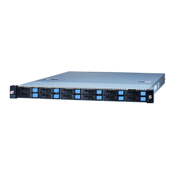
Page 27: About The Product
About the Product The following views show you the product. 1.5.1 System Front View B8252G79AE12HR-2T B8252G79V4E4HR-2T Description USB3.0 Port Drive Trays Power Button with green & red LED ID Button with blue LED http://www.tyan.com... - Page 28 Front Panel Button and LED Item Color Behavior System Power On / Green Solid On Power Button Green/Red System Power Off / All Off System Warning / Red Solid On ID Button Blue ID Located / Blue Solid On HDD LED Definitions Drive Status Activity LED (Green) Status LED (Red)
-
Page 29: System Rear View
1.5.2 System Rear View Description PSU0 ID Button OCP Card Area 10GbE LAN Port x 2 IPMI LAN Port USB3.0 Port x 2 PSU1 Full-height / Half-length PCIE Gen4 x16 Slot x 2 PSU 1+1 Redundancy Warning LED Indications PSU Status Warning LED 2 PSUs are present and system is power-on 1 PSU AC lost... - Page 30 1Gbps LAN Port 10/100/1000 Mbps LAN Link/Activity LED Scheme Left LED Right LED Link Green 10 Mbps Active Blinking Green Link Green Green 100 Mbps Active Blinking Green Green Link Green Amber 1000 Mbps(1Gps) Active Blinking Green Amber No Link 10Gbps LAN Port 10/100/1000 Mbps LAN Link/Activity LED Scheme Left LED...
-
Page 31: System Top View
1.5.3 System Top View Description Description M1725G68-USB Front USB Air Duct Board (pre-installed) M1724G68-FPB Front Panel PSU0 Board (pre-installed) Riser Card Bracket 2.5”/3.5” SSD/HDD Trays* (M8252G79-L16-1F & M8252G79-R16-1F pre-installed) System Fans PSU1 *NOTE: 1. M1312G68-BP6E-4 & M1302G68-BP12-4HDD Backplane Board (pre-installed on B8252G79V4E4HR-2T SKU) 2. -
Page 32: Chassis Dimensions
1.5.4 Chassis Dimensions http://www.tyan.com... -
Page 33: Chapter 2: Setting Up
Chapter 2: Setting Up 2.0.1 Before you Begin This chapter explains how to install the CPUs, CPU heatsinks, memory modules, and hard drives. Instructions on inserting add on cards are also given. 2.0.2 Work Area Make sure you have a stable, clean working environment. Dust and dirt can get into components and cause malfunctions. -
Page 34: Precautions
2.0.4 Precautions Components and electronic circuit boards can be damaged by discharges of static electricity. Working on a system that is connected to a power supply can be extremely dangerous. Follow the guidelines below to avoid damage to GC79-B8252/GC79A-B8252 or injury to yourself. -
Page 35: Installing Motherboard Components
Installing Motherboard Components This section describes how to install components on to the motherboard, including CPUs, memory modules and Add-on cards. 2.1.1 Removing the Chassis Cover Follow these instructions to remove the GC79-B8252/GC79A-B8252 chassis cover. 1. Push the latches simultaneously and slide backwards. 2. - Page 36 4. Slide out the drive trays. Unscrew the front top cover and then slide it forwards to lift it up. http://www.tyan.com...
-
Page 37: Replacing The Chassis Cover
2.1.2 Replacing the Chassis Cover Follow these instructions to replace the GC79-B8252/GC79A-B8252 chassis cover. 1. Place the front top cover on the chassis. Slide it backwards until it clicks. Fasten two screws. 2. Place the rear top cover on the chassis. Push the latches simultaneously and slide it forwards to close. -
Page 38: Installing The Cpu And Heat Sink
2.1.3 Installing the CPU and Heat sink Follow the steps below to install CPUs and CPU heat sinks. 1. Use a T20 Torx screwdriver to loosen the screws securing the force frame in a sequential order (3->2->1). NOTE: The force frame will automatically eject after the captive screws are being released. - Page 39 3. Remove the external cap from the rail frame. Using your thumbs and forefinger, remove the PnP cap by lifting it up vertically. 4. Align and install the carrier frame with package into the slot on the rail frame. 5. Carefully close the rail frame with the installed package. Then push both edges of the rail frame firmly until it locks in place.
- Page 40 NOTE: During installation, observe the following: 1. Make sure to push the carrier frame with package towards the end of the rail frame until it clicks into place. 2. Do not drop the carrier frame or touch the package pad to avoid component damage. 6.
-
Page 41: Installing The Memory
2.1.4 Installing the Memory The following instruction is a sample showing how to install a memory module. Follow these instructions to install the memory modules onto the motherboard. Press the memory slot locking levers in the direction of the arrows as shown in the following illustration. - Page 42 DIMM Location NOTE: 1. √ indicates a populated DIMM slot. 2. Use paired memory installation for max performance. 3. Populate the same DIMM type in each channel, specifically - Use the same DIMM size - Use the same # of ranks per DIMM 4.
- Page 43 Recommended Memory Population Table Dual CPU installed (CPU0 and CPU1) Quantity of Memory installed P0_D1_UMC0_CH_A0 √ √ √ √ P0_D1_UMC0_CH_A1 √ √ √ √ √ √ √ √ P0_D1_UMC1_CH_B0 √ √ P0_D1_UMC1_CH_B1 √ √ √ √ √ √ P0_D0_UMC1_CH_C0 √ √...
-
Page 44: Installing The Expansion Card
2.1.5 Installing the Expansion Card Follow these instructions to install the expansion card. 1. Unscrew to lift up the riser card bracket. 2. Unscrew to remove the dummy bracket. 3. Insert the PCI-E card into the slot and screw it firmly to the riser card bracket. 4. -
Page 45: Installing The 2.5" Hard Drive
2.1.6 Installing the 2.5” Hard Drive Follow these instructions to install the 2.5” hard drives for B8252AE12HR-2T SKU. 1. Press the locking tab to pull the lever open. 2. Slide the drive tray out. 3. Press the locking tab to pull the tray side rail open. http://www.tyan.com... - Page 46 4. Align the hard drive with the guide pins and install the hard drive into the drive tray. Close the tray side rail. http://www.tyan.com...
- Page 47 5. Insert the drive tray into the chassis and close the lever. http://www.tyan.com...
-
Page 48: Installing The Slim 2.5" Hard Drives
2.1.7 Installing the Slim 2.5” Hard Drives Follow these instructions to install the slim 2.5” hard drives for B8252G79V4H4HR-2T SKU. 1. Press the locking tab to pull the lever open. 2. Slide the drive tray out. 3. Align the hard drive with the guide pins and install the hard drive into the drive tray. - Page 49 4. Insert the drive tray into the chassis and close the lever. http://www.tyan.com...
-
Page 50: Installing The 3.5" Hard Drives
2.1.8 Installing the 3.5” Hard Drives Follow these instructions to install the 3.5” hard drives for B8252G79V4H4HR-2T SKU. 1. Press the locking tab to pull the lever open. 2. Slide the drive tray out. 3. Pull the tray side rail open. http://www.tyan.com... - Page 51 4. Align the hard drive with the guide pins and install the hard drive into the drive tray. Close the tray side rail. 5. Insert the drive tray into the chassis and close the lever. http://www.tyan.com...
-
Page 52: Installing The Micro Sd Card
2.1.9 Installing the Micro SD Card Follow these instructions to install the Micro SD Card. 1. Open the protection cap. 2. Insert the Micro SD Card into the slot and close the cap. 3. Slide the protection cap slightly forwards to lock. http://www.tyan.com... -
Page 53: Installing The M.2 Latch
2.1.10 Installing the M.2 Latch Follow these instructions to install the M.2 Latch. 1. Take out the M.2 Latch from the AK box. 2. Measure the length of the M.2 card and insert the latch into the appropriate hole. 3. Turn the M.2 Latch 90 to the left. - Page 54 4. Insert the M.2 card into the slot. Pull the latch to lock the M.2 card. http://www.tyan.com...
-
Page 55: Rack Mounting
Rack Mounting After installing the necessary components, GC79-B8252/GC79A-B8252 can be mounted in a rack using the supplied rack mounting kit. Rack mounting kit Rails x 2 Screw Sacks x 2 2.2.1 Installing the Server in a Rack Follow these instructions to mount the GC79-B8252/GC79A-B8252 into an industry standard 19”... -
Page 56: Installing Slide Rails To The Rack
2.2.2 Installing Slide Rails to the Rack Take out the tool-less rail set from the accessory kit. Push the white tab in the direction as the arrow shows to draw out the inner rail. Attach the inner rails to both sides of the chassis. Push the inner rails backwards to lock in place. - Page 57 NOTE: Use a screwdriver to slightly push the latch open and then push the inner rail forwards to unlock. Attach the outer rail to the rack. Pull the latch open and align the square stud with the square hole on the rack rail. Please note that the square stud must be fully attached inside the square hole and then close the latch to lock.
- Page 58 Front http://www.tyan.com...
-
Page 59: Rack Mounting The Server
2.2.3 Rack mounting the Server 1. Install the chassis. Draw out the rails half way and then slide the chassis into the rails. Must be done with at least 2 people. Properly place the chassis directly on the rack and install. 2. - Page 60 3. Fasten the chassis ear to the front surface of chassis. http://www.tyan.com...
-
Page 61: Removing The Server From Rack
2.2.4 Removing the Server from Rack Release the chassis ears by loosening the screws. Pull out the chassis half way to the lock position. Push the white locking tabs forwards to slide the chassis all out from the rack. Caution: Remove the server from the rack carefully. - Page 62 NOTE http://www.tyan.com...
-
Page 63: Chapter 3: Replacing Pre-Installed Components
Chapter 3: Replacing Pre-Installed Components Introduction This chapter explains how to replace the pre-installed components, including the S8252 Motherboard, M1724G68-FPB Front Panel Board, M1725G68-USB Front USB Board, M8252G79-L16-1F & M8252G79-R16-1F Riser Cards, four HDD Backplane Boards, System Fan and Power Supply etc. Disassembly Flowchart The following flowchart outlines the disassembly procedure. -
Page 64: Removing The Cover
Removing the Cover Follow Chapter 2.1.1 to remove the cover of GC79-B8252/GC79A-B8252. Replacing the Power Supply To replace the power supply follow these instructions. 1. Press the latch as shown to pull out the power supply module. 2. Replace a new single power and reinsert it into the power cage following the above steps in reverse. -
Page 65: Replacing The Front Panel Board
Replacing the Front Panel Board Follow these instructions to replace the M1724G68-FPB Front Panel Board. 1. Loosen 3 screws to release the front panel bezel from the chassis. 2. Loosen 2 screws to remove the front panel cage and bracket. 3. -
Page 66: Front Panel Board Features
3.5.1 Front Panel Board Features Front View Rear View M1724G68-FPB Front Panel Board Form Factor 33.5*21*1.6 mm (1) Signal Connector (J1) Integrated I/O (1) PWR Button (1) ID Button http://www.tyan.com... -
Page 67: Replacing Front Usb Board
Replacing Front USB Board Follow these instructions to replace the M1725G68-USB Front USB Board. 1. Loosen 3 screws to release the front USB bezel from the chassis. 2. Loosen 2 screws to remove the USB cage and bracket. 3. Disconnect the cable and unscrew the USB Board. 4. -
Page 68: Front Usb Board Features
3.6.1 Front USB Board Features Front View Rear View M1725G68-USB Front USB Board Form Factor 31.9*19.4*1.6 mm (1) Signal Connector (J2) Integrated I/O (1) USB3.0 Connector http://www.tyan.com... -
Page 69: Replacing The Hdd Backplane Board
Replacing the HDD Backplane Board Follow these instructions to replace the HDD Backplane Boards. B8252G79V4E4HR-2T SKU (M1312G68-BP6E-4 & M1302G68-BP12-4 pre-installed) 1. Disconnect all cables connected to the M1312G68-BP6E-4 HDD Backplane Board. Slide out the hard drive trays and unscrew to remove the M1312G68-BP6E-4 HDD BP Board. - Page 70 B8252G79AE12HR-2T SKU (M1299G68A-BPE-12 pre-installed) 1. Disconnect all cables connected to the M1299G68A-BPE-12 HDD Backplane Board. Slide out the hard drive trays and use a screwdriver to unscrew the M1299G68A-BPE-12 HDD Backplane Board. Life up the BP Board for replacement. 2. After replacing with a new HDD Backplane Board, follow the procedures described earlier in reverse order to reinsert the HDD Backplane Board into the chassis.
-
Page 71: Hdd Bp Board Features
3.7.1 HDD BP Board Features Front View Rear View M1299G68A-BPE-12 HDD Backplane Board (for B252G79AE12HR-2T SKU) Form Factor 435*38.3*2.6 mm PCI-EGen3 12-pot NVMe U.2 BP Board (12) Hot-swap 2.5” NVMe U.2 SSD (2) ATX 2x4-pin Power Connector (2) 5V connector for DOM Integrated I/O (6) Slim-SAS 8i connector (8) Fan connector... - Page 72 Front View Rear View M1302G68-BP12E-4 HDD Backplane Board (for B8252G79V4E4HR-2T SKU) Form Factor 433.95*38.2*2.6 mm PCI-EGen3 4-port 3.5”/2.5” HDD BP Board, supports 4x SATA 6G/s & SAS 12Gb/s (1) Big 4-pin Power Connector (PW2) Integrated I/O (1) ATX 4x2-pin Power Connector (J30) (1) Mini-SAS HD Connector (6) Fan Connector (1) 2x15-pin Fan Control Connector (J31)
- Page 73 Front View M1312G68-BP6E-4 HDD Backplane Board (for B8252G79V4E4HR-2T SKU) Form Factor 303*40.1*1.6 mm PCI-EGen3 4-port 2.5” slim HDD BP Board (4) Hot-swap slim SATA 6Gb/s SSD or (4) hot-swap slim 2.5” NVMe U.2 Integrated I/O (1) ATX 8-pin Power Connector (J1) (4) OCULink Connector (4) SATA Connector http://www.tyan.com...
-
Page 74: Replacing The Riser Card
Replacing the Riser Card Follow these instructions to replace the M8252G79-L16-1F M8252G79-R16-1F Riser Card. Unscrew to lift up the Riser Card Bracket from the chassis. Unscrew to replace with a new riser card. Follow the steps described earlier in reverse order to reinstall the riser card bracket. -
Page 75: Riser Card Feature
3.8.1 Riser card Feature M8252G79-L16-1F Riser Card 29.6*136.6mm Form Factor PCI-E x16 Gen3 adapter card Specification (1) PCI-E x16 Gen3 slot support (1) PCI-E x16 Add-on card M8252G79-R16-1F Riser Card 29.6*136.6mm Form Factor PCI-E x16 Gen3 adapter card Specification (1) PCI-E x16 Gen3 slot support (1) PCI-E x16 Add-on card http://www.tyan.com... -
Page 76: Replacing The Fan
Replacing the Fan Follow these instructions to replace the fan module. Disconnect the fan cable to lift up the fan module for replacement. 4. To replace a new 40x40x28mm Fan, release the fan rubbers and rivets from the fan module. Replace with a new fan and then insert the fan rubbers and rivets. 5. -
Page 77: Replacing The Motherboard
3.10 Replacing the Motherboard After removing all of the aforementioned components, follow these instructions to remove the motherboard from the chassis. 1. Disconnect all cables. The following shows three cable routing configurations. B8252G79AE12HR-2T SKU B8252G79V4E4HR-2T SKU http://www.tyan.com... - Page 78 2. Use a screwdriver to loosen cable holder screws and then remove cable holders. 3. Use a screwdriver to loosen 6 OCP 3.0 screws and remove OCP 3.0 rails. http://www.tyan.com...
- Page 79 4. Unscrew the motherboard to lift it up for replacement. http://www.tyan.com...
- Page 80 NOTE http://www.tyan.com...
-
Page 81: Chapter 4: Motherboard Information
Unplug the power from your computer power supply and then touch a safely grounded object to release static charge (i.e. power supply case). For the safest conditions, MiTAC recommends wearing a static safety wrist strap. (2) Hold the motherboard by its edges and do not touch the bottom of the board, or flex the board in any way. -
Page 82: Board Image
Board Image S8252GM2NE-2T This picture is representative of the latest board revision available at the time of publishing. The board you receive may not look exactly like the above picture. http://www.tyan.com... -
Page 83: Block Diagram
Block Diagram S8252 Block Diagram http://www.tyan.com... -
Page 84: Motherboard Mechanical Drawing
Motherboard Mechanical Drawing http://www.tyan.com... -
Page 85: Board Parts, Jumpers And Connectors
Board Parts, Jumpers and Connectors This diagram is representative of the latest board revision available at the time of publishing. The board you receive may not look exactly like the above diagram. The DIMM slot numbers shown above can be used as a reference when reviewing the DIMM population guidelines shown later in the manual. - Page 86 Motherboard Components Connectors 32. SSI 8-pin Power Connector (PE_PW2) 1. Rear IO ID LED Button(IDLED_BTN1) 33. NVME Hot plug Header (J26) 2. NMI Button(NMI_BTN1) 3. Power Button (PWR_BTN1) 34. Slim SAS CON(SATA/PCIE) (J12) 35. Slim SAS CON(SATA/PCIE) (J34) 4. Reset Button (COLD_RST_BTN1) 36.
- Page 87 d. COM2/5 Change (J201) j. Disable SMBUS5 For CPU1 VR (J68) e. Clear COMS Jumper (J64) k. Update Power VR FW (PJ1) f. SGPIO/SMBUS Change(J51) PCIE Slots A. PCIE4.0 Slot x16 (J24) D. PCIE4.0 Slot x24 (J21) B. OCP 3.0 Slot (OCP3_0) E.
- Page 88 CPU0_FAN/CPU1_FAN/ SYS_FAN_1/SYS_FAN_2/ SYS_FAN_3/ SYS_FAN_4/ SYS_FAN_5/ SYS_FAN_6: 4 -Pin CPU FAN Connector Signal P12V FAN_TACH Use this header to connect the cooling fan to your motherboard to keep the system stable and reliable. CPU0_FAN_1: CPU0 FAN Connector CPU1_FAN_1: CPU1 FAN Connector COM2/5 / COM1: COM1/2 Port Header Signal Signal...
- Page 89 USB3_FPIO1: Front USB2.0/USB3.0 *2 Header Signal Signal P0_RX_N P0_RX_P P1_RX_N P1_RX_P P0_TX_N P0_TX_P P1_TX_N P1_TX_P P0_N P0_P P1_N OC_N P1_P TYPEA_USB3: Vertical Type-A USB3.0 Connector Signal Signal SSRX- SSRX+ USB DATA2- USB DATA2+ SSTX- SSTX+ SGPIO Header (P0_SATA_SGPIO0/ P0_SATA_SGPIO1/ P1_SATA_SGPIO1) Signal Signal SDIN...
- Page 90 FAN_HD1: Front Fan Connector Signal Signal TACH_SYS1 TACH_SYS6 TACH_SYS2 TACH_SYS7 TACH_SYS3 TACH_SYS8 TACH_SYS4 TACH_SYS9 TACH_SYS5 TACH_SYS10 PWM_SYS2 PWM_SYS1 TACH_SYS11 BMC_DAT3 TACH_SYS12 BMC_CLK3 VDD3_DUAL PWM_SYS3 VDD3_DUAL TACH_SYS13 TACH_CPU1 TACH_SYS14 TACH_CPU0 PWM_SYS4 PWM_SYS5 PWM_CPU0 J20/J25/J26/J27: 7 Pin Header for hot plug Signal Signal VDD_33_Dual HP_CLK...
- Page 91 PE_PW2: 8-pin Power Connector to HDD BP Signal Signal P12_HDD2 P12_HDD2 P12_HDD2 P12_HDD2 PE_PW3: 8-pin Power Connector to HDD BP Signal Signal P12_HDD3 P12_HDD3 P12_HDD3 P12_HDD3 NOTE: The 8-pin GPU power connector can support up to 20A. PE_PW4: 8-pin Power Connector to GPU Card Signal Signal P12_GPU1...
- Page 92 HD_PW3: 8-pin Power Connector to GPU Card Signal Signal VDD_12_PSU VDD_5_RUN SHD_PW4/ SHD_PW5/ SHD_PW6/ SHD_PW7/SHD_PW8 Signal Signal VDD_12_PSU VDD_5_RUN http://www.tyan.com...
-
Page 93: Thermal Interface Material
Thermal Interface Material There are two types of thermal interface materials designed for use with the processors. The most common material comes as a small pad attached to the heat sink at the time of purchase. There should be a protective cover over the material. -
Page 94: Tips On Installing Motherboard In Chassis
Tips on Installing Motherboard in Chassis Before installing your motherboard, make sure your chassis has the necessary motherboard support studs installed. These studs are usually metal and are gold in color. Usually, the chassis manufacturer will pre-install the support studs. If you are unsure of stud placement, simply lay the motherboard inside the chassis and align the screw holes of the motherboard to the studs inside the case. - Page 95 Some chassis include plastic studs instead of metal. Although the plastic studs are usable, MITAC recommends using metal studs with screws that will fasten the motherboard more securely in place. Below is a chart detailing what the most common motherboard studs look like and how they should be installed.
-
Page 96: Installing The Memory
Installing the Memory Before installing memory, ensure that the memory you have is compatible with the motherboard and processor. Check the TYAN Web site at http://www.tyan.com details of the type of memory recommended for your motherboard. (16+16) DIMM slots support /(L)RDDR4 up to 3200 w/ ECC (1.2V) ... - Page 97 SP3/SP4 Families Support Table1.DIMM Interleaving Guidelines DIMM Channel B Channel A Notes Population DIMM0 DIMM1 DIMM0 DIMM1 NV-NVDIMM Populating NVDIMMs NVDIMMs are identical only per channel pair. D-R,LR, or 3DS DIMM type Populating NVDIMMs with capacity-2x D RDIMMs or capacity LRDIMMs Table2.DIMM Interleaving Guidelines Slots...
- Page 98 Recommended Memory Population Table Dual CPU installed (CPU0 and CPU1) Quantity of Memory installed P0_D1_UMC0_CH_A0 √ √ √ √ P0_D1_UMC0_CH_A1 √ √ √ √ √ √ √ √ P0_D1_UMC1_CH_B0 √ √ P0_D1_UMC1_CH_B1 √ √ √ √ √ √ P0_D0_UMC1_CH_C0 √ √...
-
Page 99: Finishing Up
Finishing Up Congratulations on making it this far! You have finished setting up the hardware aspect of your computer. Before closing up your chassis, make sure that all cables and wires are connected properly, especially SATA cables and most importantly, jumpers. - Page 100 NOTE http://www.tyan.com...
-
Page 101: Chapter 5: Bios Setup
Chapter 5: BIOS Setup About the BIOS The BIOS is the basic input/output system, the firmware on the motherboard that enables your hardware to interface with your software. The BIOS determines what a computer can do without accessing programs from a disk. The BIOS contains all the code required to control the keyboard, display screen, disk drives, serial communications, and a number of miscellaneous functions. -
Page 102: Getting Help
Chipset section unless you are absolutely sure of what you are doing. The Chipset defaults have been carefully chosen either by MiTAC or your system manufacturer for best performance and reliability. Even a seemingly small change to the Chipset setup options may cause the system to become unstable or unusable. -
Page 103: Main Menu
Main Menu In this section, you can alter general features such as the date and time. Note that the options listed below are for options that can directly be changed within the Main Setup screen. BIOS Information It displays BIOS related information. Memory Information This displays the total memory size. -
Page 104: Advanced Menu
Advanced Menu This section facilitates configuring advanced BIOS options for your system. Onboard Device Configuration Onboard Device and Function Configuration PCIE Slot Configuration Onboard PCIE Slot Configuration Trusted Computing Trusted Computing Setting Redfish Host Interface Settings Redfish Host Interface Parameters Hardware Health Configuration Hardware health Configuration S5 RTC Wake Settings... - Page 105 Serial Port Console Redirection Serial Port Console Redirection CPU Configuration CPU Configuration Parameters AST2500 Super IO Configuration System Super IO Chip Parameters PCI Subsystem Settings PCI, PCI-X and PCI Express Settings USB Configuration USB Configuration Parameters. Network Stack Configuration Network Stack Settings CSM Configuration CSM Configuration, Enable/Disable Option ROM execution setting, etc.
-
Page 106: Onboard Device Configuration
5.3.1 Onboard Device Configuration Onboard VGA Enable/Disable ASPEED VGA. Disabled / Enabled Active Video Select between onboard or external VGA support. Onboard Offboard Onboard LAN Enable/Disable Onboard LAN Devices. Disabled Enabled NMI Button Enable or Disable NMI button Disabled Enabled Clock Spread Spectrum Enable/Disable CG1_PLL Spread Spectrum Disabled... - Page 107 Serial IRQ Mode Configure Serial IRQ Mode Quiet Continuous http://www.tyan.com...
-
Page 108: Pcie Slot Configuration
5.3.2 PCIE Slot Configuration J1-J2 SATA or NVMe link Select Select link header function as Nvme or SATA function NVMe / SATA J3-J4 SATA or NVMe link Select Select link header function as Nvme or SATA function NVMe / SATA J5-J6 SATA or NVMe link Select Select link header function as Nvme or SATA function NVMe / SATA... - Page 109 OCP Slot Link Width Configuration OCP Slot Link Width Configuration, Auto is detected by GPIO (x8x8/x16) x4x4x4x4 / x8x8 / x16 Riser 1 Up Slot Link Width Configuration Setting PCIe Slot Link Width x4x4x4x4 / x8 / x16 Riser 2 Up Slot Link Width Configuration Setting PCIe Slot Link Width, Auto is detected by GPIO (x8x8/x16) x4x4x4x4 / x8 / x16 Riser 3 Middle Slot Link Width Configuration...
- Page 110 Riser 3 Down Slot Link Speed Onboard PCIE Slot Link Speed Configuration Auto / Gen 1 (2.5 GT/s) / Gen 2 (5 GT/s) / Gen 3 (8 GT/s) Riser 4 Down Slot Link Speed Onboard PCIE Slot Link Speed Configuration Auto / Gen 1 (2.5 GT/s) / Gen 2 (5 GT/s) / Gen 3 (8 GT/s) http://www.tyan.com...
-
Page 111: Trusted Computing
5.3.3 Trusted Computing Security Device Support Enable or disable BIOS support for security device. O.S. will not show Security device. O.S. will not show Security Device. TCG EFI protocol and INT1A interface will not be available. Enabled / Disabled Disable Block Sid Override to allow SID authentication in TCG Storage device. -
Page 112: Redfish Host Interface Settings
5.3.4 Redfish Host Interface Settings Read only. http://www.tyan.com... -
Page 113: Hardware Health Configuration
5.3.5 Hardware Health Configuration Auto Fan Control Auto Fan Control help. Automatic / Manual / Full Speed BMC Alert Beep Enable/Disable BMC Alert Beep On / Off NOTE: When Auto Fan Control is set to [Manual], PWM Minimal Duty Cycle item will appear. - Page 114 Greenwell Enabled or Disabled Advanced System Power Saving Enabled / Disabled Number of PSU Number of PSU 1 / 2 / 3 http://www.tyan.com...
- Page 115 5.3.5.1 Sensor Data Register Monitoring When you enter the Sensor Data Register Monitoring submenu, you will see the following dialog window pop out. Please wait 8~10 seconds. NOTE: SDR can not be modified. Read only. http://www.tyan.com...
-
Page 116: S5 Rtc Wake Settings
5.3.6 S5 RTC Wake Settings Wake system from S5 Enable or disable system wake on alarm event. Select Fixed time, system will wake on the hr::min::sec specified. Select dynamic time, system will wake on the current time+ increase minute(s) Disabled / Fixed time / Dynamic time When Wake system from S5 is set to [Fixed Time] Wake up hour Select 0-23. -
Page 117: Serial Port Console Redirection
5.3.7 Serial Port Console Redirection COM1/COM2 Console Redirection Console redirection enable or disable. Disabled / Enabled Console Redirection Settings The settings specify how the host computer (which the user is using) will exchange data. Both computers should have the same or compatible settings. NOTE: Console Redirection Settings menu only appear when Console Redirection was set to [Enabled]. - Page 118 5.3.7.1 COM1 Console Redirection Settings Terminal Type Emulation: ANSI: Extended ASCII charset. VT100: ASCII charset. VT100+: Extends VT100 to support color function keys, etc. VT-UTF8: Uses UTF8 encoding to map Unicode chars onto 1 or more bytes. VT-UTF8 / VT100 / VT100+ / ANSI Bits per Second Select serial port transmission speed.
- Page 119 Stop Bits Stop bits indicate the end of a serial data packet. (A start bit indicates the beginning). The standard setting is 1 stop bit. Communication with slow devices may require more than 1 stop bit. 1 / 2 Flow Control Flow Control can prevent data loss from buffer overflow.
- Page 120 5.3.7.2 COM2 Console Redirection Settings Terminal Type Emulation: ANSI: Extended ASCII charset. VT100: ASCII charset. VT100+: Extends VT100 to support color function keys, etc. VT-UTF8: Uses UTF8 encoding to map Unicode chars onto 1 or more bytes. VT-UTF8 / VT100 / VT100+ / ANSI Bits per Second Select serial port transmission speed.
- Page 121 Stop Bits Stop bits indicate the end of a serial data packet. (A start bit indicates the beginning). The standard setting is 1 stop bit. Communication with slow devices may require more than 1 stop bit. 1 / 2 Flow Control Flow Control can prevent data loss from buffer overflow.
- Page 122 5.3.7.3 Legacy Serial Redirection Settings Legacy Serial Redirection Port Select a COM port to display redirection of Legacy OS and Legacy OPROM Messages COM1 / COM2 Resolution On Legacy OS, the Number of Rows and Columns supported redirection 80x24 / 80x25 Redirect After POST When Bootloader is selected, then Legacy Console Redirection is disabled before booting to legacy OS.
- Page 123 5.3.7.4 Serial Port for Out-Of-Band Management/Windows Emergency Services (EMS) Console Redirection Settings Out-of Band Mgmt Port Microsoft Windows Emergency Management Services (EMS) allows for remote management of a Windows Server OS through a serial port. COM1 / COM2 Terminal Type VT-UTF8 is the preferred terminal type for out-of-band management.
- Page 124 buffers are empty, a ‘start’ signal can be sent to restart the flow. Hardware flow control uses two wires to send start/stop signal. None / Hardware RTS/CTS Data Bits / Parity / Stop Bits Read only. http://www.tyan.com...
-
Page 125: Cpu Configuration
5.3.8 CPU Configuration SVM Mode Enable/disable CPU Virtualization Enabled / Disabled SMEE Control secure memory encryption enable Enabled / Disabled CPU 0 / CPU 1 Information View Information related to CPU 0 / CPU 1 http://www.tyan.com... - Page 126 5.3.8.1 CPU 0 Information Read only. http://www.tyan.com...
- Page 127 5.3.8.2 CPU 1 Information Read only. http://www.tyan.com...
-
Page 128: Ast2500 Super Io Configuration
5.3.9 AST2500 Super IO Configuration Serial Port 1 / Serial Port 2 View and Set Basic properties of the SIO Logical device. Like IO Base, IRQ Range, DMA Channel and Device Mode. http://www.tyan.com... - Page 129 5.3.9.1 Serial Port 1 Configuration Use This Device Enable or Disable this Logical Device. Enabled / Disabled NOTE: When Use This Device item setting to [Disabled], the following menu will disappear. Possible Allows the user to change the device resource settings. New settings will be reflected on this setup page after system restarts.
- Page 130 5.3.9.2 Serial Port 2 Configuration Use This Device Enable or Disable this Logical Device. Enabled / Disabled NOTE: When Use This Device item setting to [Disabled], the following menu will disappear. Possible Allows the user to change the device resource settings. New settings will be reflected on this setup page after system restarts.
-
Page 131: Pci Subsystem
5.3.10 PCI Subsystem Above 4G Decoding Globally Enable or Disables 64bit capable Devices to be decoded in Above 4G Address Space(Only if System supports 64 bit PCI Decoding). Enabled / Disabled SR-IOV Supporting If system has SR-IOV capable PCIe devices, this option Enables or Disables Single Root IO virtualization Support Enabled / Disabled PCI Express Settings... - Page 132 5.3.10.1 PCI Express Settings Maximum Payload Set Maximum Payload of PCI Express Device or allow System BIOS to select the value. Auto / 128 Bytes / 256 Bytes / 512 Bytes Maximum Read Request Set Maximum Read Request Size of PCI Express Device or allow system BIOS to select the value.
-
Page 133: Usb Configuration
5.3.11 USB Configuration Legacy USB Support Enable USB legacy support. AUTO option disables legacy support if no USB devices are connected. DISABLE option will keep USB devices available only for EFI applications. Enabled / Disabled / Auto XHCI Hand-off This is a workaround for OSes without XHCI hand-off support. The XHCI ownership change should be claimed by XHCI driver Enabled / Disabled USB Mass Storage Driver Support... - Page 134 USB transfer time-out The time-out value for Control, Bulk and Interrupt transfers. 20 sec / 10 sec / 5 sec / 1 sec Device reset time-out USB mass storage device Start Unit command time-out. 20 sec / 10 sec / 30 sec / 40 sec Device power-up delay Maximum time the device will take before it properly reports itself to the Host Controller.
-
Page 135: Network Stack Configuration
5.3.12 Network Stack Configuration NOTE: The BIOS will automatically read the onboard LAN controller. Network Stack Enable/Disable UEFI Network Stack. Enabled / Disabled NOTE: The following items are not available when Network Stack is set to [Disabled]. Ipv4 PXE Support Enable IPV4 PXE Boot Support. - Page 136 Ipv6 PXE Support Enable IPV6 PXE Boot Support. If disabled IPV6 PXE boot option will not be created. Disabled / Enabled Ipv6 HTTP Support Enable IPV6 HTTP Boot Support. If disabled IPV6 HTTP boot option will not be created. Disabled / Enabled IPSEC Certificate Support to Enable/Disable IPSEC certificate for Ikev.
-
Page 137: Csm Configuration
5.3.13 CSM Configuration CSM support Enable/Disable CSM Support Enabled / Disabled Option ROM Messages Set display mode for Option ROM Force BIOS / Keep Current Network Controls the execution of UEFI and legacy PXE OpROM Do not launch / UEFI / Legacy Storage Controls the execution of UEFI and legacy PXE OpROM Do not launch / UEFI / Legacy... - Page 138 Other PCI devices Determines OpRom execution policy for devices other than network, storage, or video Do not launch / UEFI / Legacy http://www.tyan.com...
-
Page 139: Nvme Configuration
5.3.14 NVMe Configuration Read only. http://www.tyan.com... - Page 140 5.3.14.1 INTEL SSDPE2MD400G4 Read only. http://www.tyan.com...
-
Page 141: Sata Configuration
6.3.15 SATA Configuration Read only. http://www.tyan.com... -
Page 142: Nvdimm Force Self Refresh Configuration
5.3.16 NVDIMM Force Self Refresh Configuration Asset NVDIMM Save on Reset Asset NVDIMM Save on cold reset and warm reset Enabled / Disabled Asset NVDIMM Save on Shutdown Asset NVDIMM Save on Shutdown Enabled / Disabled http://www.tyan.com... -
Page 143: Tis Auth Configuration
5.3.17 TIs Auth Configuration Server CA Configuration Press <Enter> to configure Server CA. Client Cert Configuration Read only. http://www.tyan.com... - Page 144 5.3.17.1 Server CA Configuration Enroll Cert Press <Enter> to enroll cert. Delete Cert Press <Enter> to delete cert. http://www.tyan.com...
- Page 145 5.3.17.1.1 Enroll Cert Enroll Cert Using File Enroll Cert Using File. Cert GUID Input digit character in 11111111-2222-3333-4444-1234567890ab format. Commit Changes and Exit Commit Changes and Exit. Discard Changes and Exit Discard Changes and Exit. http://www.tyan.com...
- Page 146 5.3.17.1.2 Delete Cert FE9C6606-8B49-44A3-8B6B-DEA3A0E0324D GUID for CERT. Enabled / Disabled http://www.tyan.com...
-
Page 147: Iscsi Configuration
5.3.18 iSCSI Configuration Please follow the instructions to initiate the iSCSI function. Step 1. Select Advanced CSM Configuration Network [UEFI]. Step 2. Select Advanced Network Stack Configuration Network Stack [Enabled] Step 3. Save changes and reboot. iSCSI Initiator Name The worldwide unique name of iSCSI Initiator. - Page 148 5.3.18.1 Add an Attempt Read only. NOTE: Only LAN1 supports iSCSI function. http://www.tyan.com...
- Page 149 5.3.18.1.1 MAC AA:27:85:F7:C4:43 iSCSI Mode Disabled, Enabled, Enabled for MPIO. Disabled / Enabled / Enabled for MPIO Internet Protocol Initiator IP address is system assigned in IP6 mode. In Autoconfigure mode, iSCSI driver will attempt to connect iSCSI target via IPv4 stack, if failed then attempt IPv6 stack.
- Page 150 Configure ISID OUI-format ISID in 6 bytes, default value is derived from MAC address. Only last 3 bytes are configurable. Example: update 0ABBCCDDEEFF to OABBCCF07901 by input F07901. Enable DHCP Enable DHCP. Disabled / Enabled Initiator IP Address Enter IP address in dotted-decimal notation. Initiator Subnet Mask Enter IP address in dotted-decimal notation.
- Page 151 5.3.18.2 Delete Attempts Commit Changes and Exit Commit Changes and Exit. Discard Changes and Exit Discard Changes and Exit. http://www.tyan.com...
- Page 152 5.3.18.3 Change Attempt Order Commit Changes and Exit Commit Changes and Exit. Discard Changes and Exit Discard Changes and Exit. http://www.tyan.com...
-
Page 153: Vlan Configuration
5.3.19 VLAN Configuration Enter Configuration Menu Press ENTER to enter configuration menu for VLAN configuration. http://www.tyan.com... - Page 154 5.3.19.1 Enter Configuration Menu VLAN ID VLAN ID of new VLAN or existing VLAN, valid value is 0~4094. Priority 802.1Q Priority, valid value is 0~7. Add VLAN Create a new VLAN or update existing VLAN. Remove VLAN Remove selected VLANs. http://www.tyan.com...
-
Page 155: Mac Aa2785F7C443-Ipv4 Network Configuration
5.3.20 MAC AA2785F7C443-IPv4 Network Configuration Configured Indicate whether network address configured successfully or not. Disabled / Enabled Save Changes and Exit Save Changes and Exit. http://www.tyan.com... -
Page 156: Mac Aa2785F7C443-Ipv6 Network Configuration
5.3.21 MAC AA2785F7C443-IPv6 Network Configuration Enter Configuration Menu Press ENTER to enter configuration menu for IPv6 configuration. http://www.tyan.com... - Page 157 5.3.21.1 Enter Configuration Interface ID The 64 bit alternative interface ID for the device. The string is colon separated, e.g. ff:dd:88:66:cc:1:2:3 MAC AA:27:85:F7:C4:43 DAD Transmit Count The number of consecutive Neighbor Solicitation messages sent while performing Duplicate Address Detection on a tentative address. A value of zero indicates that Duplicate Address Detection is not performed.
-
Page 158: Chipset Menu
Chipset Menu PCIe Link Training Type PCIe Link training in 1 or 2 steps. 1 Step / 2 Step PCIe Compliance Mode PCIe Link Compliance Mode Off / On North Bridge North Bridge Parameters http://www.tyan.com... -
Page 159: North Bridge Configuration
5.4.1 North Bridge Configuration Socket 0 Information View Information related to socket 0 Socket 1 Information View Information related to Socket 1 http://www.tyan.com... - Page 160 5.4.1.1 Socket 0 Information Read only. http://www.tyan.com...
- Page 161 5.4.1.2 Socket 1 Information Read only. http://www.tyan.com...
-
Page 162: Amd Cbs
AMD CBS CPU Common Options CPU Common Options. DF Common Options DF Common Options. UMC Common Options UMC Common Options. NBIO Common Options NBIO Common Options. FCH Common Options FCH Common Options. http://www.tyan.com... -
Page 163: Cpu Common Options
5.5.1 CPU Common Options Platform First Error Handling Enable/disable PFEH, cloak individual banks, and mask deferred error interrupt from each bank. Enabled / Disabled / Auto Core Performance Boost Disable CPB Disabled / Auto Global C-state Control Controls IO based C-state generation and DF C-states. Enabled / Disabled / Auto Local APIC Mode xAPIC / x2APIC / Auto... - Page 164 5.5.1.1 Performance CCD/Core/Thread Enablement CCD/Core/Thread Enablement http://www.tyan.com...
- Page 165 5.5.1.1.1 CCD/Core/ Thread Enablement CCD Control Sets the number of CCDs to be used. Once this option has been used to remove any CCDs, a POWER CYCLE is required in order for future selections to take effect. Auto / 2 CCDs / 3 CCDs / 4 CCDs / 6 CCDs Core control Sets the number of cores to be used.
- Page 166 5.5.1.2 Prefetcher settings L1 Stream HW Prefetcher Option to Enable / Disable L1 Stream HW Prefetcher Disable / Enable / Auto L2 Stream HW Prefetcher Option to Enable / Disable L1 Stream HW Prefetcher Disable / Enable / Auto http://www.tyan.com...
-
Page 167: Df Common Options
5.5.2 DF Common Options http://www.tyan.com... - Page 168 5.5.2.1 Memory Addressing NUMA nodes per socket Specifies the number of desired NUMA nodes per socket. Zero will attempt to interleave the two sockets together. NPS0 / NPS1 / NPS2 / NPS4 / Auto Memory interleaving Allows for disabling memory interleaving. Note that NUMA nodes per socket will be honored regardless of this setting.
- Page 169 5.5.2.2 ACPI ACPI SRAT L3 Cache As NUMA Domain Enabled: Each CCX in the system will be declared as a separate NUMA domain. Disabled: Memory Addressing\NUMA nodes per socket will be declared. Disabled / Enabled / Auto ACPI SLIT Distance Control Determines how the SLIT distances are declared.
-
Page 170: Umc Common Options
5.5.3 UMC Common Options http://www.tyan.com... - Page 171 5.5.3.1 DDR4 Common Options http://www.tyan.com...
- Page 172 5.5.3.1.1 DRAM Timing Configuration Overclock Memory Overclock Settings. Auto / Enabled http://www.tyan.com...
- Page 173 5.5.3.1.2 Security TSME Transparent SME: AddrTweakEn=1; ForceEncrEn =1;DataEncrEn=0 Disabled / Enabled / Auto Data Scramble Data scrambling: DataScrambleEn Disabled / Enabled / Auto http://www.tyan.com...
- Page 174 5.5.3.2 DRAM Memory Mapping Chipselect Interleaving Interleave memory blocks across the DRAM chip selects for node 0. Disabled / Auto BankGroupSwap BankGroupSwapAlt default = Enabled in BIOS, which has priority than BankGroupSwap. BIOS equation: If BankGroupSwap =Disabled Endif. Please set BankGroupSwapAlt to Disabled while set BankGroupSwap to Enabled.
-
Page 175: Nbio Common Options
5.5.4 NBIO Common Options IOMMU Enable/Disable IOMMU Disabled / Enabled / Auto ACS Enable AER must be enabled for ACS enable to work to work Disabled / Enabled / Auto PCIe ARI Support Enable Alternative Routing-ID Interpretation Disabled / Enabled / Auto Enable AER Cap Enables Advanced Error Reporting Capability Disabled / Enabled / Auto... - Page 176 Preferred IO Preferred IO Select Type Manual: Bus Number manually Auto: Default Auto / Manual Loopback Mode Enable/Disable Pcie Loopback Mode Disabled / Enabled / Auto CV Test Set this to Enabled to support running PCIECV tool. Auto – preserve h/w defaults Disabled / Enabled / Auto http://www.tyan.com...
- Page 177 5.5.4.1 SMU Common Options Determinism Control Auto = Use the fused Determinsm Manual = User can set customized Determinism Manual / Auto cTDP Control Auto = Use the fused cTDP Manual = User can set customized TDP*** TDP is used to define the RC thermal model only *** Manual / Auto EfficiencyModeEn...
- Page 178 APBDIS 0= not APBDIS (mission mode) 1= APBDIS 0 / 1 / Auto DF Cstates Enable = Enable DF C-states Disable = Disable DF C-states Disabled / Enabled / Auto HSMP Support Select HSMP support enable or disable Disabled / Enabled / Auto Diagnostic Mode Select Diag mode enable or disable Disabled / Enabled / Auto...
-
Page 179: Fch Common Options
5.5.5 FCH Common Options http://www.tyan.com... - Page 180 5.5.5.1 Ac Power Loss Options Restore Ac Power Loss Select Ac Loss Control Method Power Off / Power On / Last State http://www.tyan.com...
- Page 181 5.5.5.2 FCH RAS Options Reset after sync flood Enable AB to forward downstream sync-flood message to system controller. Disabled / Enabled / Auto http://www.tyan.com...
-
Page 182: Server Management
Server Management FRB-2 Timer Enable or Disable FRB-2 timer (POST timer) Disabled / Enabled NOTE: When [FRB-2 Timer] is set to [Enabled], the following items will be available. FRB-2 Timer timeout Enter value Between 3 to 6 min for FRB-2 Timer Expiration value 3 minutes / 4 minutes / 5 minutes / 6 minutes / 12 minutes FBR-2 Timer Policy Configure how the system should respond if the FRB-2 Timer expires. - Page 183 OS Watchdog Timer If enabled, starts a BIOS timer which can only be shut off by management Software after the OS loads. Helps determine that the OS successfully loaded or follows the OS Boot Watchdog Timer policy. Disabled / Enabled NOTE: When [OS Watchdog Timer] is set to [Enabled], the following items will be available.
- Page 184 5.6.1 System Event Log SEL Components Change this to enable or disable event Logging for error/ progress codes during boot. Disabled / Enabled Erase SEL Choose options for erasing SEL. No / Yes, on next reset / No, on every reset When SEL is Full Choose options for reactions to a full SEL.
- Page 185 5.6.2 BMC Network Configuration Configure IPv4 support Management Port1 Configuration Address Source Select the configure LAN channel parameters statically or dynamically (by BIOS or BMC). Unspecified option will not modify any BMC network parameters during BIOS phase. Unspecified / Static / DynamicBmcDhcp / DynamicBmcNonDhcp Management Port 2 Enable/Disable BMC Share Nic.
- Page 186 Configuration Address source Select to configure LAN channel parameters statically or dynamically (by BIOS or BMC). Unspecified option will not modify any BMC network parameters during BIOS phase Unspecified / Static / DynamicBmcDhcp Management Port 2 IPV6 Support Enable or Disable LAN2 IPV6 Support Enabled / Disabled Configuration Address source Select to configure LAN channel parameters statically or dynamically (by BIOS or...
- Page 187 5.6.3 BMC User Settings Add User Press <Enter> to Add a User. Add User Press <Enter> to Delete a User. Add User Press <Enter> to Change User Settings. http://www.tyan.com...
- Page 188 5.6.3.1 Add User Read only. http://www.tyan.com...
- Page 189 5.6.3.2 Delete User User Name Enter BMC User Name. User Password Read only. http://www.tyan.com...
- Page 190 5.6.3.3 Change User Settings User Name Enter BMC User Name. User Password Read only. http://www.tyan.com...
-
Page 191: Security
Security Administrator Password Set administrator password in the Create New Password window. After you key in the password, the Confirm New Password window will pop out to ask for confirmation. User Password Set user password in the Create New Password window. After you key in the password, the Confirm New Password window will pop out to ask for confirmation. - Page 192 5.7.1 Secure Boot Secure Boot Secure Boot feature is Active if Secure Boot is Enabled, Platform Key(PK) is enrolled, and the system is in User mode. The mode change requires platform reset Disabled / Enabled Secure Boot Mode Secure Boot mode options: Standard or Custom. In Custom mode Secure Boot Policy variables can be configured by a physically present user without full authentication Custom / Standard...
- Page 193 5.7.1.1 Key Management Configuration Factory Key Provision Install factory default Secure Boot keys after the platform reset and while the System is in Setup mode Disabled / Enabled NOTE: The follow menu will be free when [Provision Factory Defaults] is set to [Enabled].
- Page 194 Enroll SHA256 hash of the binary into Autorized Signature Database (db) Remove‘UEFI CA’from DB Device Guard ready system must not list ‘Microsoft UEFI CA’ Certificate in Authorized Signature database (db) Restore DB defaults Restore DB variable to factory defaults Platform Key(PK) Enroll Factory Defaults or load certificates from a file: 1.
- Page 195 Forbidden Signatures Enroll Factory Defaults or load certificates from a file: 1. Public Key Certificate in: a)EFI_signature_LIST b)EFI_CERT_X509 (DER encoded) c)EFI_CERT_RSA2048(bin) d)EFI_CERT_SHA256,384,512 2.Autheticated UEFI Variable 3.EFI PE/COFF Image (SHA256) Key Source: Default, External, Mixed, Test Update / Append Authorized TimeStamps Enroll Factory Defaults or load certificates from a file: 1.
-
Page 196: Boot
Boot Setup Prompt Timeout Number of seconds to wait for setup activation key. 65535 (0xFFFF) means indefinite waiting. Bootup NumLock State Select the keyboard NumLock state. Off / On Quiet Boot Enable or disable Quiet Boot option. Disabled / Enabled Endless Boot Enable or disable Endless Boot. - Page 197 Wait For “ESC” If Error Enable or disable wait ‘ESC’ key Function. When chassis intrusion CMOS clear or BMC not Response. Disabled / Enabled Boot Option Priorities Boot Option #1 Sets the system boot order. Device Name / Device Name / Disabled Boot Option #2 Sets the system boot order.
-
Page 198: Delete Boot Option
5.8.1 Delete Boot Option Delete Boot Option Remove an EFI boot option from the boot order Select one to Delete / UEFI: Built-in EFI Shell http://www.tyan.com... -
Page 199: Save & Exit
Save & Exit Save Changes and Exit Exit system setup after saving the changes. Discard Changes and Exit Exit system setup without saving any changes. Save Changes and Reset Reset the system after saving the changes. Discard Changes and Reset Reset system setup without saving any changes. - Page 200 Save as User Defaults Save the changes done so far as User Defaults. Restore User Defaults Restore the User Defaults to all the setup options. http://www.tyan.com...
-
Page 201: Chapter 6: Diagnostics
Chapter 6: Diagnostics NOTE: if you experience problems with setting up your system, always check the following things in the following order: Memory, Video, CPU By checking these items, you will most likely find out what the problem might have been when setting up your system. -
Page 202: Amibios Post Code (Aptio)
AMIBIOS Post Code (Aptio) The POST code checkpoints are the largest set of checkpoints during the BIOS pre-boot process. The following table describes the type of checkpoints that may occur during the POST portion of the BIOS: Checkpoint Ranges Status Code Range Description 0x01 –... - Page 203 Status Code Description 0x0A OEM initialization after microcode loading 0x0B Cache initialization SEC Error Codes 0x0C – 0x0D Reserved for future AMI SEC error codes 0x0E Microcode not found 0x0F Microcode not found SEC Beep Codes None PEI Phase Status Code Description Progress Codes 0x10...
- Page 204 Status Code Description 0x31 Memory Installed 0x32 CPU post-memory initialization is started 0x33 CPU post-memory initialization. Cache initialization 0x34 CPU post-memory initialization. Application Processor(s) (AP) initialization 0x35 CPU post-memory initialization. Boot Strap Processor (BSP) selection 0x36 CPU post-memory initialization. System Management Mode(SMM) initialization 0x37 Post-Memory North Bridge initialization is started 0x38...
- Page 205 Status Code Description 0xE0 S3 Resume is started (S3 Resume PPI is called by the DXE IPL) 0xE1 S3 Boot Script execution 0xE2 Video repost 0xE3 OS S3 wake vector call 0xE4 – 0xE7 Reserved for future AMI progress codes S3 Resume Error Codes 0xE8 S3 Resume Failed...
- Page 206 # of Beeps Description S3 Resume failed Reset PPI is not available DXE Phase Status Code Description 0x60 DXE Core is started 0x61 NVRAM initialization 0x62 Installation of the South Bridge Runtime Services 0x63 CPU DXE initialization is started 0x64 CPU DXE initialization (CPU module specific) 0x65 CPU DXE initialization (CPU module specific)
- Page 207 Status Code Description 0x80 – 0x8F OEM DXE initialization codes 0x90 Boot Device Selection (BDS) phase is started 0x91 Driver connecting is started 0x92 PCI Bus initialization is started 0x93 PCI Bus Hot Plug Controller initialization 0x94 PCI Bus Enumeration 0x95 PCI BUS Request Resources 0x96...
- Page 208 Status Code Description 0xB0 Runtime Set Virtual Address MAP Begin 0xB1 Runtime Set Virtual Address MAP End 0xB2 Legacy Option ROM initialization 0xB3 System Reset 0xB4 USB hot plug 0xB5 PCI bus hot plug 0xB6 Clean-up of NVRAM 0xB7 Configuration Reset (reset of NVRAM settings) 0xB8 –...
- Page 209 # of Beeps Description Reset protocol is not available Platform PCI resource requirements cannot be met ACPI/ASL Checkpoints Status Code Description 0x01 System is entering S1 sleep state 0x02 System is entering S2 sleep state 0x03 System is entering S3 sleep state 0x04 System is entering S4 sleep state 0x05...
- Page 210 NOTE http://www.tyan.com...
-
Page 211: Appendix I: How To Recover Uefi Bios
Appendix I: How to recover UEFI BIOS Important Notes: The emergency UEFI BIOS Recovery process is only used to rescue a system with a failed or corrupted BIOS image that fails to boot to an OS. It is not intended to be used as a general purpose BIOS flashing procedure and should not be used as such. - Page 212 The system will boot to BIOS setup. A new menu item will appear at the far right of the screen. Scroll to the 'Recovery' tab, move the curser to “Proceed with flash update” and press the "Enter" key on the keyboard to start the BIOS recovery process.
-
Page 213: Appendix Ii: Cable Connection Tables
Appendix II: Cable Connection Tables B8252G79AE12HR-2T SKU Slim-SAS 8I Cable Front Backplane (BP) Board to S8252MB HDD BP Cable Connect to S8252GM2NE-2T/MB M1303G68A-BP12E-12 NVME0,1 Slim-SAS 8I SlimSAS 8I NVME2,3 Slim SAS 1 SlimSAS 8I NVME4,5 Slim SAS 2 ... - Page 214 B8252G79V4E4HR-2T SKU Slim-SAS 8I Cable Front Backplane (BP) Board to S8252MB HDD BP Cable Connect to S8252GM2NE-2T/MB M1302G68-BP12-4 Slim-SAS 8I to Mini-SAS HD SATA 0-3 SLIMSAS J12 Front Backplane (BP) Board to S8252MB HDD BP Cable Connect to S8252GM2NE-2T/MB M1312G68-BP6E-4 NVME0 ...
-
Page 215: Appendix Iii: Fan And Temp Sensors
Appendix III: Fan and Temp Sensors This section aims to help readers identify the locations of some specific FAN and Temp Sensors on the motherboard. A table of BIOS Temp sensor name explanation is also included for readers’ reference. Figure 1: Sensor Location NOTE: The red mark indicates the sensor. - Page 216 Fan and Temp Sensor Location: Fan Sensor: It is located in the third pin of the fan connector, which detects the fan speed (rpm) Temp Sensor: refer to Figure 1: Sensor Location. They detect the system temperature around. BIOS Temp Sensor Name Explanation: http://www.tyan.com...
- Page 217 http://www.tyan.com...
- Page 218 http://www.tyan.com...
- Page 219 BIOS Temp Sensor Name Explanation P0_Tctl_Value Temperature of the CPU0 P1_Tctl_Value Temperature of the CPU1 SYS_Air_Inlet Temperature of System Air Inlet Area MB_Air_Inlet Temperature of MB Air Inlet Area SYS_Air_Outlet Temperature of System Air Outlet Area OCP_Air_Inlet Temperature of System OCP Air Inlet Area X550_Temp ...
- Page 220 SYS_FAN_4 Fan Speed of System Fan4 SYS_FAN_5 Fan Speed of System Fan5 SYS_FAN_6 Fan Speed of System Fan6 SYS_FAN_7 Fan Speed of System Fan7 PSU0 Current Status of PSU0 PSU0_FAN Fan Speed of PSU0 PSU1 Current Status of PSU1 PSU1_FAN Fan Speed of PSU1 http://www.tyan.com...
-
Page 221: Appendix Iv: Fru Parts Table
Appendix IV: FRU Parts Table GC79-B8252/GC79A-B8252 FRU Parts Item Model Number Part Number Picture Description Power FRU-PS-0320 471100000417 1200W PSU Supply FRU-TS-0260 336210000073 22000RPM,40*40*56mm,8PIN fan FRU-TS-0270 422T60300001 31000RPM,40*40*28mm,8PIN fan Heatsink & FRU-TH-0260 343T58100002 Heatsink Cooler M8252G79-L16-1F 411T62500003 Riser Card M8252G79-R16-1F 411T62500007 Riser Card M1724G68-FPB... - Page 222 FRU-CS-1510 422T62500012 SlimSAS 8i 74P RE/2*OCuLink 4X 42P,450mm FRU-CS-1520 422T62500010 SlimSAS 8i 74P LE/2*OCuLink 4X 42P,450mm SlimSAS 8i 74P LE/2*Short Mini-SAS HD FRU-CS-1530 422T62500011 36P,700mm FRU-CS-1570 422T62500009 SlimSAS 8i 74P RE/SlimSAS 8i 74P,530mm Cable FRU-CS-1580 422T62500007 SlimSAS 8i 74P/SlimSAS 8i 74P LE,400mm SlimSAS 8i RE to SlimSAS 8i CABLE,SlimSAS FRU-CS-1590 422T62500008...
-
Page 223: Appendix V: Technical Support
With all these convenient resources just a few keystrokes away, users can easily find their latest software and operating system components to keep their systems running as powerful and productive as possible. MITAC also ranks high for its commitment to fast and friendly customer support through email. By offering plenty of options for users, MITAC serves multiple market segments with the industry’s most competitive services to support them. - Page 224 Returning Merchandise for Service During the warranty period, contact your distributor or system vendor FIRST for any product problems. This warranty only covers normal customer use and does not cover damages incurred during shipping or failure due to the alteration, misuse, abuse, or improper maintenance of products.
Need help?
Do you have a question about the TYAN GC79-B8252 and is the answer not in the manual?
Questions and answers