Table of Contents
Advertisement
Quick Links
Advertisement
Table of Contents

Related Manuals for A&A Tech EEM MOT 01 FL02.01


Summary of Contents for A&A Tech EEM MOT 01 FL02.01
- Page 1 Operators and Maintenance Manual Page 1/16 Display EEM MOT 01 FL02.01 Operators and Maintenance Manual Display EEM MOT 01 FL02.01 Rev. 01 – October 2017 Copyright: Auto & Aero Technologies Sp. z o.o. Mazowiecka 10/5, 20-723 Lublin, Poland ■ email: info@aatech.pl ■ www.aatech.pl...
-
Page 2: Table Of Contents
Operators and Maintenance Manual Page 2/16 Display EEM MOT 01 FL02.01 Table of Contents Introduction ..................... 3 General information ................3 Handling in transport and storage ............. 4 Installation ..................5 3.1. Environmental specifications............ 5 3.2. Dimensions ................5 3.3. -
Page 3: Introduction
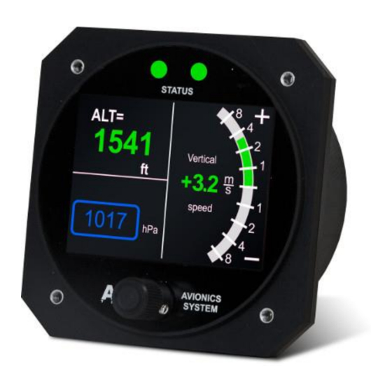
Operators and Maintenance Manual Page 3/16 Display EEM MOT 01 FL02.01 Introduction This instrument is intended for ultralight, microlight, homebuilt and experimental aircraft. The purpose of EEM MOT 01 type display is to present key flight information to the pilot. Version FL02.01 displays altitude and vertical speed of the aircraft. -
Page 4: Handling In Transport And Storage
Operators and Maintenance Manual Page 4/16 Display EEM MOT 01 FL02.01 during installation and in its operating phase. This document does not contain rules and guidelines on operation of aircraft instruments at large. Read the manual thoroughly before turning on the instrument and precisely follow the instructions to install and configure it. -
Page 5: Installation
Operators and Maintenance Manual Page 5/16 Display EEM MOT 01 FL02.01 3. Installation 3.1. Environmental specifications The EEM MOT 01 display has been designed to be installed in non- hermetic cockpits of ultralight aircrafts of ceiling not exceeding 3 000 m (10 000 ft). -
Page 6: Mounting
Operators and Maintenance Manual Page 6/16 Display EEM MOT 01 FL02.01 3.3. Mounting The display should be located conveniently within the pilot’s view in the control panel in the cockpit. The diameter of the mounting hole to be cut in the panel is 80mm. It is recommended that the display is installed from the rear side the control panel. - Page 7 Operators and Maintenance Manual Page 7/16 Display EEM MOT 01 FL02.01 The EEM MOT 01 display is connected to the system by in-built MOLEX Ultra-Fit 3.5 mm 6 pin male connector located at the back of the instrument. A schematic diagram of the connection is shown in Figure 4 and in Table 1.
-
Page 8: Operation And Maintenance
Operators and Maintenance Manual Page 8/16 Display EEM MOT 01 FL02.01 4. Operation and maintenance The display is to be connected to AUX AVS 2. The front panel of EEM MOT 01 is composed of three elements: the display, two status diodes (alert indication), and the encoder knob & push- button for setting parameters (Fig. - Page 9 On client’s request, warning and alarm threshold values may be set for some of the above parameters according to the specification provided by the aircraft supplier. Default threshold values are listed in Table 2. Tab. 2. Parameters displayed by EEM MOT 01 FL02.01 display Symbol/ Range of...
- Page 10 Operators and Maintenance Manual Page 10/16 Display EEM MOT 01 FL02.01 encoder knob. Figure 7 presents the idea of colour codes and warning/alarm indication. Fig. 7. The idea of flight parameter status information Thus, information on the status of a flight parameter is presented in two...
-
Page 11: Service, Diagnostics And Repairs
Operators and Maintenance Manual Page 11/16 Display EEM MOT 01 FL02.01 green – flight parameters within normal range; orange – warning; – alarm; 2) by means of the colour of digits and bar graph (if applicable) presenting the value of the parameter: green –... -
Page 12: Checks
Operators and Maintenance Manual Page 12/16 Display EEM MOT 01 FL02.01 5.2. Checks The following checks are recommended: 1) At pre-flight check: Turn on the power to check if operational; 2) After 100 hours of flight: Check the instrument’s electric connections;... -
Page 13: Repairs
Operators and Maintenance Manual Page 13/16 Display EEM MOT 01 FL02.01 Fig. 8. Indication of no connection to measurement modules c) In the case of the instrument’s failure or malfunction, turn power off and on again. d) If the above does not solve the problem, the display needs to be replaced. -
Page 14: Spare Parts
Operators and Maintenance Manual Page 14/16 Display EEM MOT 01 FL02.01 by means of service software provided by the Manufacturer and the dedicated diagnostic interface. 5.7. Spare parts The instrument does not contain any user-serviceable parts. The user is not allowed to disassemble it nor replace any subassemblies. - Page 15 Operators and Maintenance Manual Page 15/16 Display EEM MOT 01 FL02.01 a) mechanical damages and damages resulting from them, b) unauthorised repairs, damage caused by abuse or misuse, d) unauthorised alterations to hardware or software. 8. The warranty does not cover claims that arise from the product parameters unless they are different from values declared by Auto &...
- Page 16 Operators and Maintenance Manual Page 16/16 Display EEM MOT 01 FL02.01 The information in this document is subject to change without notice and should not be construed as commitment by Auto & Aero Technologies Sp. z o.o. These technical data and the information embodied therein are the property of Auto &...
Need help?
Do you have a question about the EEM MOT 01 FL02.01 and is the answer not in the manual?
Questions and answers