Table of Contents
Advertisement
Quick Links
Advertisement
Table of Contents

Related Manuals for A&A Tech EEM MOT 01


Summary of Contents for A&A Tech EEM MOT 01
- Page 1 Operators and Maintenance Manual Page 1/16 Display EEM MOT 01 FE01.05 Operators and Maintenance Manual Display EEM MOT 05 FE01.01 Rev. 01 – March 2020 Copyright: Auto & Aero Technologies Sp. z o.o. Mazowiecka 10/5, 20-723 Lublin, Poland ■ email: info@aatech.pl ■ www.aatech.pl...
-
Page 2: Table Of Contents
Operators and Maintenance Manual Page 2/16 Display EEM MOT 01 FE01.05 Table of Contents Introduction ....................3 General information ................3 Handling in transport and storage ............4 Installation ..................... 5 3.1. Environmental specifications ............5 3.2. Dimensions .................. 5 3.3. -
Page 3: Introduction
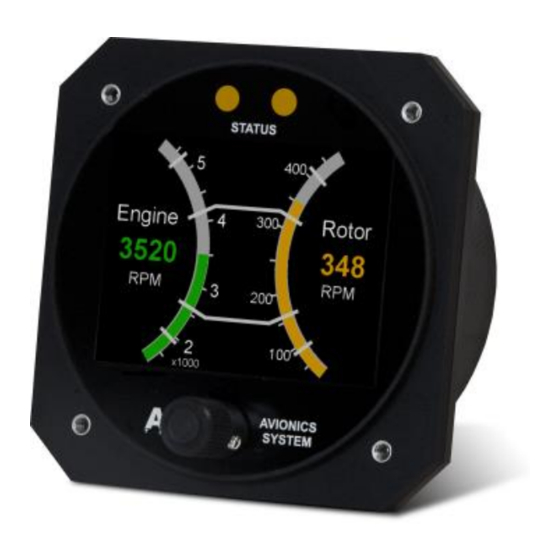
Introduction This instrument is intended for ultralight, microlight, homebuilt and experimental aircraft. The purpose of EEM MOT 01 type display is to present key engine status information to the pilot. Version FE01.05 displays engine speed, inlet air pressure, oil pressure and temperature. -
Page 4: Handling In Transport And Storage
Auto & Aero Technologies Sp. z o.o. with all the resulting consequences. 2. Handling in transport and storage The EEM MOT 01 monitor is bubble-wrapped to protect it against vibration and other physical damage, and packed in a cardboard box together with the warranty card. -
Page 5: Installation
3. Installation 3.1. Environmental specifications The EEM MOT 01 display has been designed to be installed in non- hermetic cockpits of ultralight aircrafts of ceiling not exceeding 3 000 m (10 000 ft). Acceptable range of operating parameters is listed below: •... -
Page 6: Mounting
Fig. 3. Mounting hole and screw holes measurements (not to scale) 3.4. Power and wiring The EEM MOT 01 display is powered from the aircraft power system. Power specifications: nominal supply voltage 12V, acceptable supply voltage range 8 ÷ 30V, current < 85mA. - Page 7 7/16 Display EEM MOT 01 FE01.05 The EEM MOT 01 display is connected to the system by in-built MOLEX Ultra-Fit 3.5 mm 6 pin male connector located at the back of the instrument. A schematic diagram of the connection is shown in Figure 4 and in Table 1.
-
Page 8: Operation And Maintenance
4. Operation and maintenance The display is to be connected to EMS DAQ R2. The front panel of EEM MOT 01 is composed of three elements: the display, two status diodes (alert indication), and the encoder knob & push- button for setting parameters (Fig. 5). - Page 9 On client’s request, warning and alarm threshold values may be set for some of the above parameters according to the specification provided by the aircraft supplier. Default threshold values are listed in Table 2. Tab. 2. Parameters displayed by EEM MOT 01 FE01.05 display Symbol/ Range of...
- Page 10 Operators and Maintenance Manual Page 10/16 Display EEM MOT 01 FE01.05 status diodes. Exceeding the alarm threshold is additionally indicated by the diodes flashing red. The pilot can switch off flashing by pushing the encoder knob. Figure 7 presents the idea of colour codes and warning/alarm indication.
-
Page 11: Service, Diagnostics And Repairs
Operators and Maintenance Manual Page 11/16 Display EEM MOT 01 FE01.05 Fig. 7. The idea of flight parameter status information 5. Service, diagnostics and repairs 5.1. Service life a) TBO of the display is not defined. Copyright: Auto & Aero Technologies Sp. z o.o. -
Page 12: Checks
Operators and Maintenance Manual Page 12/16 Display EEM MOT 01 FE01.05 b) In the case of failure or error, the display must not be used any more. 5.2. Checks The following checks are recommended: 1) At pre-flight check: Turn on the power to check if operational;... -
Page 13: Repairs
Operators and Maintenance Manual Page 13/16 Display EEM MOT 01 FE01.05 Fig. 8. Indication of no connection to measurement modules c) In the case of the instrument’s failure or malfunction, turn power off and on again. d) If the above does not solve the problem, the display needs to be replaced. -
Page 14: Spare Parts
Operators and Maintenance Manual Page 14/16 Display EEM MOT 01 FE01.05 by means of service software provided by the Manufacturer and the dedicated diagnostic interface. 5.7. Spare parts The instrument does not contain any user-serviceable parts. The user is not allowed to disassemble it nor replace any subassemblies. - Page 15 Operators and Maintenance Manual Page 15/16 Display EEM MOT 01 FE01.05 a) mechanical damages and damages resulting from them, b) unauthorised repairs, damage caused by abuse or misuse, d) unauthorised alterations to hardware or software. 8. The warranty does not cover claims that arise from the product parameters unless they are different from values declared by Auto &...
- Page 16 Operators and Maintenance Manual Page 16/16 Display EEM MOT 01 FE01.05 The information in this document is subject to change without notice and should not be construed as commitment by Auto & Aero Technologies Sp. z o.o. These technical data and the information embodied therein are the property of Auto &...
Need help?
Do you have a question about the EEM MOT 01 and is the answer not in the manual?
Questions and answers