Table of Contents
Advertisement
Quick Links
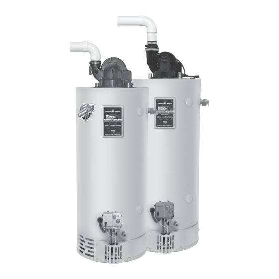
Ultra Low NOx Residential & Light Duty
Power Vent 75 Gallon Models
Power Vent 75 Gallon Models
Manual 238-51562-00B 1/19
Commercial Gas
SERVICE
SERVICE
MANUAL
MANUAL
Troubleshooting Guide
and Instructions for Service
(To be performed ONLY by
qualified service providers)
Models Covered
by This Manual:
URG2PV75H*N
ULG2PV75H76*N
(*) Denotes Warranty Years
Save this manual for future reference
Advertisement
Table of Contents

Related Manuals for Bradford White URG2PV75H N Series


Summary of Contents for Bradford White URG2PV75H N Series
- Page 1 Ultra Low NOx Residential & Light Duty Commercial Gas Power Vent 75 Gallon Models Power Vent 75 Gallon Models SERVICE SERVICE MANUAL MANUAL Troubleshooting Guide and Instructions for Service (To be performed ONLY by qualified service providers) Models Covered by This Manual: URG2PV75H*N ULG2PV75H76*N (*) Denotes Warranty Years...
-
Page 2: Table Of Contents
The Bradford White UPV75 Series Through-The-Wall Gas Water Heaters Table of Contents Page UPV75 Service Procedure Introduction ..........................4 How to Use This Manual......................5 Tools Required for Service.......................5 Specifications ..........................6 Control Timings.........................8 Sequence of Operation ......................9 Troubleshooting.........................13 Burner Operation Inspection, Cleaning & Replacement ............15 Pilot Inspection, Testing &... - Page 3 UPV75 Series WARNING: If the information in these instructions is not followed exactly, a fire or explosion may result causing property damage, DANGER personal injury, or death. Do not store or use gasoline or other flammable, combustible, or corrosive vapors and liquids in FOR YOUR SAFETY the vicinity of this or any other appliance.
-
Page 4: Introduction
The Bradford White Introduction The new Bradford White URG2PV75H and ULG2PV75H water heaters are designed to provide reliable performance with enhanced standard features. New design features include reliable spark to pilot ignition system, enhanced diagnostics, simplified servicing, significantly quieter operation, additional vent lengths, and Bradford White Defender Safety System (not available on all models). -
Page 5: How To Use This Manual
It is intended for this manual to be used by qualified service personnel for the primary purpose of troubleshooting and repair of the Bradford White UPV Series water heaters. Understanding the sequence of operation section of this manual will contribute greatly to troubleshooting the water heater. -
Page 6: Specifications
UPV75 Series Specifications Power supply Dedicated 115 VAC, 60 Hz, 15A. Gas Supply Pipe Minimum 1/2” NPT (schedule 40 black iron pipe recommended). Approved Gas Natural Gas, unit must match gas type supplied. Type Gas Pressure 6.0” W.C. min. for Natural Gas, 14.0” W.C. maximum. Venting System Power vent through the wall or vertical through the roof. - Page 7 UPV75 Series Specifications Vent Tables Venting Specifications for: URG2PV75H ULG2PV75H 3" Diameter (7.6 cm) PVC Vent Connector Lengths # of Maximum Straight Minimum Straight Terminating Elbows Length ft. (m) Length ft. (m) Through the Wall 45 (13.7) 2 (.6) Through the Wall 40 (12.2) 2 (.6) Through the Wall...
-
Page 8: Control Timings
UPV75 Series Specifications Control Timings Ignition State Timing Pre-purge 15 seconds Trial for Ignition 90 seconds Flame Stabilization Period 3 seconds Inter-purge 15 seconds 1.5 seconds (2 second. maximum; 1 second Flame Failure Response Time minimum.) Post-purge 15 Seconds PS Fault Delay (failed open/close) Retry after 2 minutes Soft Lockout Retry after 5 minutes... -
Page 9: Sequence Of Operation
UPV75 Series Sequence of Operation Power Up Sequence 1. Start Up. Upon power up, the control runs a safe-start check with a typical start-up delay of 5 seconds. 2. Simulative Resistive Device. To assure no outputs are energized if the “Simulated Resistive Device” is out of range, the control will test the “Simulated Resistive Device”... - Page 10 UPV75 Series Sequence of Operation Normal Heating Sequence (cont.) 7. Steady state operation. During steady state operation, the control monitors: Temperature sensor-when set point temperature is satisfied, gas valve is shut down and blower will post purge for 15 seconds. Control LED flashes a short flash once every 4 seconds (idle) status code.
- Page 11 UPV75 Series Sequence of Operation Abnormal Operation (cont.) times, then 3 times twice with 3 second pause. The status self clears if the fault clears for at least 15 seconds. c. Water temperature in excess of ECO (energy cut out) limit -The gas control immediately turns off pilot &...
- Page 12 UPV75 Series Sequence of Operation Abnormal Operation (cont.) 5. Flame sensing fault: a. Flame lost during run-the gas control turns off pilot and main valves, runs blower for 15 seconds (inter-purge). The gas control increments the recycle count, if the recycle count has not reached its limit (4), another trial for ignition begins.
-
Page 13: Troubleshooting
UPV75 Series Troubleshooting Observe green LED indicator on electronic gas control. Status flash codes are displayed with a three second pause before repeating. Check and repair the system as noted in the troubleshooting table below. Service LED Status Control Status Probable Cause Procedure None, control... - Page 14 UPV75 Series Troubleshooting Service LED Status Control Status Probable Cause Procedure 1. Unstable pilot. 2. Pilot tube blocked or restricted. Six-one flash, Failed to light pilot. Page 18 three second 3. Oxidation build up on pilot electrode. System auto resets. pause 4.
-
Page 15: Burner Operation Inspection, Cleaning & Replacement
UPV75 SERVICE PROCEDURE I UPV75 Series Burner Operation Inspection, Cleaning and Replacement Burner Inspection At periodic intervals (every 6 months) a visual inspection should be made of the pilot and main burner for proper operation and to assure no debris is accumulating. Pilot flame should be stable, some causes for an unstable pilot flame are: a) Water heater vent is less than the allowable vent length. - Page 16 UPV75 SERVICE PROCEDURE I UPV75 Series Burner Operation Inspection, Cleaning and Replacement Burner Cleaning (cont.) Step 9. Remove manifold mount from burner inner door by removing (2) ¼” hex drive screws. Step 10. Use a stiff brush, compressed air and/or a vacuum to remove any debris build up from the manifold mount.
-
Page 17: Pilot Inspection, Testing & Replacement
UPV75 Series UPV75 SERVICE PROCEDURE II Pilot Inspection, Testing and Replacement Pilot Inspection, Testing and Replacement Step 1. Position the gas control power switch to the “OFF” position and unplug the heater from the wall outlet. Step 2. Turn off gas supply to the water heater. - Page 18 UPV75 Series UPV75 SERVICE PROCEDURE II Pilot Inspection, Testing and Replacement Pilot Inspection, Testing and Replacement (cont.) Step 13.Visually inspect igniter/flame sense electrode for oxidation build up. Carefully clean any oxidation using very fine emery cloth. Step 14.Remove pilot assembly from the burner assembly (¼”...
-
Page 19: Pressure Switch Testing & Replacement
UPV75 Series UPV75 SERVICE PROCEDURE III Pressure Switch Testing and Replacement Pressure Switch Testing WARNING 115 volt potential exposure. Step 1. Position power switch on gas Use caution to avoid personal injury. control to the “OFF” position. Step 2. Remove the three screws (Phillip’s screw driver) from control access cover on blower assembly and remove cover (see photo 1). - Page 20 UPV75 Series UPV75 SERVICE PROCEDURE III Pressure Switch Testing and Replacement Pressure Switch Replacement ‘WARNING 115 volt potential exposure. Use Step 1. Position gas control power caution to avoid personal injury. switch to “OFF” position. Step 2. Remove the three screws (Phillip’s screw driver) from control access cover on blower assembly and remove cover (see photo 3).
-
Page 21: Blower Testing & Replacement
UPV75 Series UPV75 SERVICE PROCEDURE IV Blower Testing & Replacement Blower Testing WARNING 115 volt potential exposure. Use Step 1. Position gas control caution to avoid personal injury. power switch to “ON” position and adjust control to call for heat. Step 2. - Page 22 UPV75 Series UPV75 SERVICE PROCEDURE IV Blower Testing & Replacement Blower Removal Step 1. Position gas control power switch to “OFF” position and adjust control to call for heat. Step 2. Unplug blower power cord from wall outlet. Step 3. Disconnect vent system from exhaust adapter on top of blower.
-
Page 23: Blower Temperature Switch Testing & Replacement
UPV75 SERVICE PROCEDURE V UPV75 Series Blower Temperature Switch Testing and Replacement Blower Temperature Switch Testing Step 1. Position power switch on gas WARNING control to the “OFF” position. 115 volt potential exposure. Use Step 2. Remove the three screws (Phillip’s caution to avoid personal injury. - Page 24 UPV75 SERVICE PROCEDURE V UPV75 Series Blower Temperature Switch Testing and Replacement Blower Temperature Switch Replacement Step 1. Position gas control power switch to WARNING the “OFF” position and unplug heater 115 volt potential exposure. Use from wall outlet. caution to avoid personal injury. Step 2.
-
Page 25: Gas Control Testing & Replacement
UPV75 Series UPV75 SERVICE PROCEDURE VI Gas Control Testing and Replacement Line Pressure The gas control is designed for a maximum line pressure of 14.0” W.C. and a minimum line pressure of 1.0” W.C. over the water heater’s rated manifold pressure (check rating plate). - Page 26 UPV75 Series UPV75 SERVICE PROCEDURE VI Gas Control Testing and Replacement ECO (Energy Cut Out) The Honeywell gas control is designed with an ECO device that will reset. To reset the gas control after an status code (4), turn the gas control knob to the “OFF” position and wait a minimum of (5) minutes before relighting following the instructions located on the lighting instruction label or the lighting instructions located in the installation and operation manual.
- Page 27 UPV75 SERVICE PROCEDURE VI UPV75 Series Gas Control Testing and Replacement Gas Control Removal From Water Heater Step 1. Position the gas control power switch to the “OFF” position and unplug heater from wall outlet. Step 2. Drain the heater to a point below the gas control level. Step 3.
-
Page 28: Simulated Resistive Device Testing And Replacement
UPV75 SERVICE PROCEDURE VII UPV75 Series Simulative Resistance Device Testing and Replacement Simulative Resistance Device Testing Step 1. Position power switch on gas control to the “OFF” position. Step 2. Disconnect simulated resistive device harness from gas control. Step 3. Using a multi-meter set to the ohms setting, check resistance of simulative resistance device. -
Page 29: Safety Circuit Voltage Trace
UPV75 Series UPV75 SERVICE PROCEDURE VIII Safety Circuit Voltage Trace Safety Circuit Voltage Trace NOTE: This procedure assumes a cool tank. WARNING 115 volt potential exposure. Use caution to avoid personal injury. Remove three screws (Phillip’s screw driver) from control access cover on the blower and remove the cover (see photo 21). -
Page 30: 115 Vac Circuit Trace
UPV75 Series UPV75 SERVICE PROCEDURE IX 115 VAC Trace 115 VAC Circuit Trace Step 1. Verify 115 VAC and proper WARNING polarity at wall outlet. 115 volt potential exposure. Use Step 2. With unit plugged in and control caution to avoid personal injury. power switch in the “ON”... -
Page 31: Diptube Inspection & Replacement
UPV75 Series UPV75 SERVICE PROCEDURE X Dip Tube Inspection & Replacement Diptube Inspection & Replacement WARNING Water Heater components and stored water may be HOT when performing the following steps in this procedure. Take necessary precaution to prevent personal injury. Step 1. -
Page 32: Anode Inspection & Replacement
UPV75 Series UPV75 SERVICE PROCEDURE XI Anode Inspection & Replacement Anode Inspection & Replacement WARNING Water Heater components and stored water may be HOT when performing the following steps in this procedure. Take necessary precaution to prevent personal injury. Step 1. Position on/off switch of gas control valve to the “OFF”... -
Page 33: Flue Baffle Inspection & Replacement
UPV75 Series UPV75 SERVICE PROCEDURE XII Flue Baffle Inspection & Replacement Flue Baffle Inspection and Replacement Step 1. Position the gas control power switch to the “OFF” position and unplug blower from wall outlet. Step 2. Disconnect vent system from exhaust adapter on top of blower. Step 3. -
Page 34: Inner Door Removal, Inspection & Replacement
UPV75 SERVICE PROCEDURE XIII UPV75 Series Inner Door/Gasket Removal, Inspection & Replacement Inner Door Removal Procedure Step 1. Position gas control power switch to the “OFF” position. Step 2. Remove outer jacket burner access door. Step 3. Disconnect main burner feedline ( ”... - Page 35 UPV75 SERVICE PROCEDURE XIII UPV75 Series Inner Door/Gasket Removal, Inspection & Replacement Inner Door Gasket Replacement Procedure WARNING If the information in these instructions is not followed exactly, a fire or explosion may result causing property damage, personal injury or death. Step 1.
- Page 36 UPV75 SERVICE PROCEDURE XIII UPV75 Series Inner Door/Gasket Removal, Inspection & Replacement Installation of Inner Door With Gasket (cont.) Step 6. Replace outer jacket burner access door. Step 7. To resume operation follow the instructions located on the lighting instruction label or the lighting instructions located in the installation and operation manual.
-
Page 37: Glossary Of Terms
UPV75 Series Glossary of Terms Frozen Exhaust Vent Terminal If the exhaust vent terminal is blocked with ice or snow due to severe conditions, the pressure switch and control will not allow the burner to operate. This will result in a three flash status code. - Page 38 UPV75 Series Glossary of Terms 12. Inlet Dip Tube 23. Main Burner Orifice 1. Blower Complete 2. Air Mixing Inlet Cover 13. Wire Harness 24. Main Burner Feedline 3. Pressure Switch 14. T&P Valve 25. Resettable Thermal Switch 4. Blower Temp. Switch 15.
Need help?
Do you have a question about the URG2PV75H N Series and is the answer not in the manual?
Questions and answers