Table of Contents
Advertisement
Quick Links
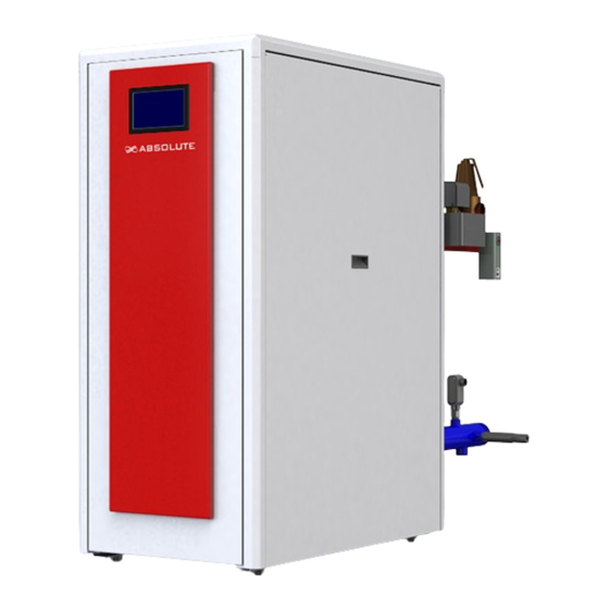
Gas-Fired Condensing Hot Water Boiler
750
ABS - 750
ABS - 900
900
ABS - 1050
1050
- Cast Aluminum Sectional Heat Exchanger
- 10 to 1 Turndown Ratio
- Honeywell Sola Boiler Control System
- Compact Light Weight Packaged Boiler
- Three Models from:
ABS 750, ABS 900, ABS 1050
- Low NO
Standard
x
Innovative industrial Inc.
Document # 1050-20
Installation and Operation Manual
MBH
MBH
MBH
CATION
Please read this manual and retain a copy for future
reference. Improper Installation, adjustment, alterations,
service or maintainer can cause serious injury, property
damage or death. Refer to this manual for assistances
or additional information or consult a qualified installer,
service agent.
Hamilton, Ontario, Canada L8l 3R5
ABS 750-900-1050/IOM Manual/V.01/12/2015
Innovative Industrial Inc.
122 Burton Street
Advertisement
Table of Contents

Related Manuals for Absolute ABS-750

Summary of Contents for Absolute ABS-750
- Page 1 Gas-Fired Condensing Hot Water Boiler Installation and Operation Manual ABS - 750 ABS - 900 ABS - 1050 1050 - Cast Aluminum Sectional Heat Exchanger - 10 to 1 Turndown Ratio CATION - Honeywell Sola Boiler Control System Please read this manual and retain a copy for future - Compact Light Weight Packaged Boiler reference.
- Page 2 Absolute Boilers 750-900-1050 CATION Before you install and operate this boiler, please read this manual carefully in its entirety. If for whatever reason you are not clear of any details, please do not hesitate to contact us as shown below. Please read all safety and warnings symbols.
-
Page 3: Table Of Contents
2.2 Operational principal of boiler 2.3 View of boiler for service connections 3. Technical Data 3.2 Boiler Service Clearance 3.2 Technical Data Sheet 3.3 Absolute Boiler Specifications 3.4 Ordering options 4. Installation: 4.1 General installation Instructions 4.2 Delivery and installation 4.2.1 Site preparation... - Page 4 Absolute Boilers 750-900-1050 4.6.5 Typical water system layout 4.6.6 Frost Protection 5 Electrical 5.1 General 5.2 Main power voltage 5.2 Control unit 5.2.1 Sola Model R7910A-1027 5.2.2 Honeywell Sola R7910A 1027 control (sheet 1-12) 5.3 Limit Controls 5.3.1 Temperature control 5.3.2 Low water level protection (LWCO) (flow and content)
- Page 5 Absolute Boilers 750-900-1050 10. Maintenance 10.1 General Maintenance 10.1.1 Inspection of air box and dirt trap 10.1.2 Cleaning the Whirlwind 10.1.3 Cleaning the fan 10.1.4 Cleaning the heat exchanger 10.1.5 Cleaning the burner assembly 10.1.6 Cleaning the siphon 10.1.7 Cleaning/replacing the ignition/ionization rod 10.1.8 Filter maintenace and filter replacement...
-
Page 6: Safety Instructions
Absolute Boilers 750-900-1050 1. SAFETY INSTRUCTIONS 1.2 Symbols The following symbols are used in this document to emphasize certain instructions. This is in order to increase your personal safety and to safeguard the technical reliability of the boiler. Indicates a potentially hazardous situation which, if ignored, may result in minor injury or product/ CAUTION property damage. -
Page 7: General Safety Notes
Absolute Boilers 750-900-1050 1.2 General safety notes Installers and operational personnel must at all times observe all safety regulations. The following warnings and cautions are general and must be given the same attention as specific precautions included in these instructions. -
Page 8: Lighting Instructions
Absolute Boilers 750-900-1050 1.3 Lighting Instructions FOR YOUR SAFETY READ BEFORE OPERATING WARNING: If you do not follow these instructions exactly, a fire or explosion may result causing property damage, personal injury or loss of life This appliance does not have a pilot. It is equipped phone. - Page 9 Europe. The cast aluminum provides a robust corrosion resistant heat exchanger that allows for ultra-high efficiencies with the added benefit of a small, light weight boiler foot print. The ABSOLUTE “ABS SERIES” heat exchanger also provides additional efficiencies with large water ways, reducing the pressure drop through the boiler! We are so confident in our heat exchanger, we provide an industry leading warranty.
- Page 10 The the Sola controls cannot override the standard flame safety controls. External controls or commands can modulate the boiler as required by the BMS. All Absolute boilers are fully test fired after assembly to ensure the boiler and controls comply with our strict quality policy.
-
Page 11: Operational Principal Of Boiler
Absolute Boilers 750-900-1050 2.2 Operational principal of boiler Combustion air is drawn into the inlet connection from the plant room (room ventilated version) or from outside via the air inlet pipe. On the inlet side of the fan is a specially designed chamber which takes gas from the multi-block and mixes it in the correct proportions with the incoming air. -
Page 12: View Of Boiler For Service Connections
Absolute Boilers 750-900-1050 2.3 View of boiler for service connections A- Combustion air supply 8” ID B- Condensate drain connection 1 1/4” NPT C- Flue gas discharge 8” ID D- Gas connection 1” NPT E- Return connection 2 1/2” NPT F- Supply connection 2 1/2”... -
Page 13: Technical Data
Absolute Boilers 750-900-1050 3. Technical Data 2 /7 ” 21” ” 5 /6 11” 1 /7 ” 1 /2 ” 1 /2 ” 2 /3 ” Boiler Control ” 2 /7 Panel ” 1 /2 1 /8 ” 1/2” Boiler Supply (male NPT) Gas Connection (NPT male) 1”... - Page 14 Absolute Boilers 750-900-1050 Absolute Boilers 750-900-1050...
-
Page 15: Boiler Service Clearance
Absolute Boilers 750-900-1050 The service side of the boiler (with the heat exchanger inspection cover) is the front. 1. Pressure Relief valve. 13. Gas Connection 27. Honeywell Touch Screen 2. Air Vent. 14. Condensate Pan 28. Gas Valve 3. Spare 15. -
Page 16: Technical Data Sheet
Absolute Boilers 750-900-1050 3.2 Technical Data Sheet Specifications Unit ABS750 ABS900 ABS1050 General Firing Sequence Operation Full modulation 75 [21.98] 90 [26.37] 105 [30.77] Minimum Fuel Input MBH[kW] 750 [219.80] 900 [263.76] 1,050 [307.72] Maximum Fuel Input MBH[kW] 70 [20.51] 84 [24.61]... -
Page 17: Absolute Boiler Specifications
Absolute Boilers 750-900-1050 3.3 Absolute Boiler Specifications: Fully assembled cast aluminum floor standing sectional hot water boiler. Premix burner with stainless steel cylinder with perforated holes for precise air-fuel mixture and velocity with a stainless tube with woven steel fiber for stable flame and heat insulation. -
Page 18: Ordering Options
Absolute Boilers 750-900-1050 3.4 Ordering options: Available in inputs from 750 to 1050 MBH, 3 models Control options: Honeywell Sola control with touch screen control Service kits for heat exchanger Condensate neutralization system with or without pump Multiple boiler control... -
Page 19: Installation
CSA & NEC electrical codes Other Regulations WARNING All Absolute boilers are CSA certified, and must not be modified or installed in any way contrary to these “Installation and operations manual. Delivery and installation The Absolute boiler is supplied fully assembled, plastic wrapped and crated on a pallet. The Unit should be completely inspected for evidence of shipping damage and shipping completeness at time of receipt. -
Page 20: Site Preparation
Absolute Boilers 750-900-1050 4.2.1 Site preparation Ensure that the site selected for the installation has the following: Access to AC input power of 120 VAC. Access to a natural gas line at a minimum gas line pressure of 3.5 inch W.C. to a maximum of 14 W.C. -
Page 21: Multiply Boiler Arrangements
Absolute Boilers 750-900-1050 4.2.3 Multiply boiler arrangements Rear 12” Front 36” Front 36” Rear 12” Front 36” Rear 12” Front 36” Rear 12” Absolute Boilers 750-900-1050... - Page 22 Absolute Boilers 750-900-1050 4.2.4 Setting the boiler in place It is recommended that a house keeping pad 4 to 6 inches high be installed to ensure proper condensate drainage. If anchoring the boiler is required due to local codes for seismic activities potential, ensure 4 holes ¾ diameter by 4 inches deep are drilled in the house keeping pad as per the dimension shown in figure# 4 The boiler frame has been drilled with 4 holes of 7/8 diameter, allowing for a ¾...
-
Page 23: Flue Gas Discharge And Air Supply
DANGER PVC or CPVC should never be used in the Absolute Boiler. PVC and CPVC is not rated for the potential flue temperatures and failure of this venting material can cause severe personnel injury or death! Use only AL 29-4C for the flue gases. -
Page 24: Vent Termination Inlet/Outlets
Each Absolute boiler is supplied with a ½ inch NPT port to house a flue gas temperature sensor. Each Absolute boiler is supplied with a ¼ NPT test port for a combustion probe. Ensure the test port in sealed after combustion analysis. -
Page 25: Room Combustion Air Supply Requirements
Absolute Boilers 750-900-1050 4.4.4 Room combustion air supply requirements: The boiler must be provided with an adequate combustion air supply, the combustion air supply requirements must be determined and sized in accordance to national and local codes having jurisdiction. CSA B149 & ANSI Z223.1 – More than one combustion air source maybe required. - Page 26 Absolute Boilers 750-900-1050 WARNING The boiler should never be operated in a negative building pressure. Caution should be exercised with exhaust fans, air handling & other devices, that could affect the buildings air pressure or combustion air supply. All venting must be arranged to avoid and prevent the accumulation of flue gas condensation.
- Page 27 Absolute Boilers 750-900-1050 Venting lengths must not exceed the minimum and maximum equivalent lengths show in chart below. Any horizontal runs of the venting must slope towards the boiler ¼ to½” per linear foot Chimney applications: This venting system uses a single vent to discharge all flue gases to the outside vertically, combustion air provided with the boiler room, the air source must be sized in accordance to national codes CSA B149 &...
-
Page 28: Co-Venting - Retrofitting
Absolute Boilers 750-900-1050 Application Note: In all applications the venting must be between the minimum and maximum equivalent vent lengths shown in. For values not shown in the chart, consult your local sales representative 4.4.6 Co-venting – Retrofitting: DANGER At the time of removal of any existing boiler is removed from a common vent system, the following steps shall be performed with each remaining appliance connected to the common vent in operation and not in operation. - Page 29 Absolute Boilers 750-900-1050 Instructions: Adjust thermostat so appliance will operate continuously. Test for spillage near and around the each of the gas appliances after 5 minutes of main burner operation. After determining that each appliance remaining connected to the common venting system properly vents when tested as outlined above, return all doors, windows, exhaust fan, fireplace dampers and any other gas burning appliance to their normal positions.
-
Page 30: Vent Terminations Installation Precautions
Absolute Boilers 750-900-1050 4.4.7 Vent terminations installation precautions: [Consult national & local codes for other requirements] All exhaust terminations for conventional chimney must be finished with a finishing cone with tapered end, with a bird/ rodent screen. All sidewall, direct vent systems must be finished with a tee termination, the combustion air inlet must be a 90°... -
Page 31: Condensate Drain Connection And Trap
4.5 Condensate drain connection and trap The Absolute boiler is fitted with a 1 ¼ NPT drain port near the back and bottom face of the condensate pan. Discharge the condensate directly into a drain. Only use synthetic material for the connecting pipe-work because of the acidity of the condensate (pH 2-5) and allow a min. -
Page 32: Water Connection
Absolute Boilers 750-900-1050 4.6 Water connection The Absolute boiler is supplied with 2 inch NPT inlet and outlet manifolds. It is advisable to install a shut off valve for the both the supply and return to allow removal of the boiler in the future. All water connections should be in compliance with national and local code requirements. -
Page 33: Water Pressure
Absolute Boilers 750-900-1050 4.6.1 Water pressure The boiler is suitable for a maximum working pressure of 80 psi [10.8 bar], the system pressure shall be at least 12 psi [0.8 bar] 4.6.2 Safety valve A safety relief valve NB certified with V or HV symbol as supplied must be installed on the boiler supply piping without any obstructions. -
Page 34: Water Treatment
Absolute Boilers 750-900-1050 4.6.3 Water treatment The heat exchanger is manufactured from aluminum alloys which will provide many years of excellent service, if maintained properly. All heat exchangers require proper water conditions to remain efficient and function properly. Failure to do so will lead to premature failures within the heat exchanger. The system should be filled with mains, cold water (this will usually have a pH of between 7 and 8). -
Page 35: Water Flow
Absolute Boilers 750-900-1050 4.6.4 Water Flow See the chart below for proper water flow requirements. Incorrect flow may cause eventual damage or premature boiler failure that may not be covered under the warranty Proper flow rates may be achieved through a combination of primary and secondary flow loops. Multiple zones and pumps may result in different flow rates at different times Consideration must be given to all possible conditions and their consequences. -
Page 36: Typical Water System Layout
Absolute Boilers 750-900-1050 4.6.5 Typical water system layout The piping diagram illustrates the minimum boiler system controls needed, the by-pass system is not necessary, but can be used in multiple heating temperature circuits. Consult all national, local and building codes having jurisdiction for other requirements regarding the boiler system. -
Page 37: Frost Protection
Absolute Boilers 750-900-1050 4.6.6 Frost Protection The boiler must be installed in a frost free area to prevent freezing of the condensate drain pan and pipe. If the temperature of the heating water drops to much, the built in unit protection activates. -
Page 38: Electrical
5.1 General The Absolute Boiler is supplied with an electronic flame ionization safety control, as standard equipment. A specially designed microprocessor is at the heart of the system. The boiler is pre-wired as shown in the wiring diagram in 12. -
Page 39: Control Unit
Absolute Boilers 750-900-1050 5.2 Control unit 5.2.1 Sola Model R7910A-1027 Voltage: 120V AC 60 Hz +10% -15% Safety time is 3 seconds Control voltage: 24 Volt DC 5.2.2 Honeywell Sola R7910A 1027 control (sheet 1-12) Honeywell Sola control with Touch screen S7999D 1006 display... - Page 40 Absolute Boilers 750-900-1050 Honeywell R7910A Control PCB Jumper Start enable Absolute Boilers 750-900-1050...
- Page 41 Absolute Boilers 750-900-1050 Absolute Boilers 750-900-1050...
- Page 42 Absolute Boilers 750-900-1050 Absolute Boilers 750-900-1050...
- Page 43 Absolute Boilers 750-900-1050 Absolute Boilers 750-900-1050...
- Page 44 Absolute Boilers 750-900-1050 Absolute Boilers 750-900-1050...
- Page 45 Absolute Boilers 750-900-1050 Absolute Boilers 750-900-1050...
- Page 46 Absolute Boilers 750-900-1050 S7999D 8 PIN Plug Connector COM1 COM2 POWER Absolute Boilers 750-900-1050...
- Page 47 Absolute Boilers 750-900-1050 Absolute Boilers 750-900-1050...
- Page 48 Absolute Boilers 750-900-1050 Absolute Boilers 750-900-1050...
-
Page 49: Limit Controls
5.3 Limit Controls 5.3.1 Temperature control The Absolute boiler is equipped with an electronic temperature limit control based on flow, return, and flue gas temperature sensors. The flow temperature is adjustable between 68-200°F [20- 93°C]. 5.3.2 Low water level protection (LWCO) (flow and content) The Absolute boiler is equipped with low water protection based on temperature differences (ΔT) between flow and... -
Page 50: High Limit Protection
Absolute Boilers 750-900-1050 The boiler has been approved and has found to be in compliance to the LWCO protection, provided the factory preset high limit and flow temperatures are not altered and the modulating controls are used and no minimum flow rate is required as the Sola control system will monitor these conditions and reduce the boiler output, finally shutting down until flow conditions improve. -
Page 51: High Gas Pressure Switch (Hgp)
Absolute Boilers 750-900-1050 5.3.5 High gas pressure switch (HGP) The boiler is equipped with a gas pressure switch that is mounted directly on the air intake housing. The gas pressure switch is pre set at the factory and should not be adjusted. -
Page 52: Gas Connection
6.1 Gas connection The Absolute boiler is suitable for use with natural gas only. The gas connection is at the back left side of the boiler . The boiler is fitted with a gas filter which is mounted within the mono block gas valve as standard to prevent dirt from contaminating the gas valve or burner assembly. -
Page 53: Gas Line Piping To Boiler
Absolute Boilers 750-900-1050 6.1.3 Gas line piping to boiler Ensure pipe sizing capability follows the recommend values based on an overall length of pipe from the meter plus the equivalent length of all fittings. Approximate sizing may be based on 1 cubic foot of natural gas supply per 1,000 BTU/ hour input. -
Page 54: Gas / Air Ratio Control
Absolute Boilers 750-900-1050 6.3 Gas / air ratio control The boiler has a pressure differential gas/air ratio control. This gas/air ratio control maintains the correct balance of gas and air quantities to the burner at a constant level under variable loads. This ensures clean and reliable combustion and high part load efficiency across the entire load range. - Page 55 Absolute Boilers 750-900-1050 To adjust low fire: Required tools- 2.5 mm hex wrench and combustion analyzer Start the boiler and observe proper settings for the system. Set the boiler to low fire, to achieve minimum firing rate of the boiler.
- Page 56 Absolute Boilers 750-900-1050 Electrical DIN Connector Upstream Flange G1/8 inlet test port Filter Valve Body Coil Test port connection #2, G 1/8 between V1 and V2; both sides. Test port connection #3, G1/8 downstream of V2; both sides. Regulator outlet pressure adjustment screw; both side 10.
-
Page 57: Commissioning
Absolute Boilers 750-900-1050 7. Commissioning: DANGER If you do not follow the commissioning instructions exactly, a fire or explosion may result causing property damage, personal injury or loss of life. 7.1 Pre operational checks Check power supply ensure fused and service disconnect provided as required by local code or authorities having jurisdiction. -
Page 58: Combustion Setting And Adjustment
Absolute Boilers 750-900-1050 7.3 Combustion setting and adjustment Chart 8 Combustion Tolerance Chart Emission Unit Range Part Load (20%) Full Load (100%) 6-9.5 8.0-4.0 <100 Check and correct, if necessary, the boiler for correct gas/ air ratio set-up. Checking takes place on full and part load, adjustment takes place only on the gas valve mono block. - Page 59 Absolute Boilers 750-900-1050 Flue port for combustion analyzer WARNING The installation of the boiler is not completed until all controls and safety device have been tested and verified for correct function and operation. It is the sole responsibility of the installer to ensure that all safety control systems and gas ignition systems and any the associated safety control are tested.
-
Page 60: Operator Interface Display
Absolute Boilers 750-900-1050 8. Operator Interface Display Warning Explosion Hazard. Improper configuration can cause fuel buildup and explosion. Operators of this display may move fuel and/ or air actuators to positions that can create hazardous burner conditions. Improper user operation may result in PROPERTY LOSS, PHYSICAL INJURY or DEATH. -
Page 61: Honeywell Sola Control Programming/Configuration
Absolute Boilers 750-900-1050 8.1 Honeywell Sola Control Programming/Configuration The Honeywell control has been fully programmed and configured by the factory for most installations, in most installation no adjustments or configurations are required, please note that optional items like, Outdoor reset, DHW production and lead/lag systems require configuration, see separate instruction provide with the kits. - Page 62 Absolute Boilers 750-900-1050 Step 2: From the Configuration window, use the slide bar on the right hand side and select the group by touching the group name. Step 3: Verify in correct group and view setting, determine the parameter in the group you wish to either view (confirm) or change, if changes to a group parameter is needed, a service password will have to be entered.
-
Page 63: Commissioning Steps
Absolute Boilers 750-900-1050 8.3 Commissioning Steps NOTE Commissioning can only be performed with the Honeywell S7999D 1006 color touch screen display All units are fully factory tested, due to varying field conditions, boiler must be tested on final site for safety shutdown, operation, and combustion limits. - Page 64 Absolute Boilers 750-900-1050 Touch the Diagnostics test button, screen changes to the Modulating Test window Press the Maximum Modulation button (High fire position), this will force the boiler into the High fire position. Once in the High fire postion and stable conditions are reached check the following: Check combustion (see table) for factory and field combustion limits Adjust main flow (High fire) as necessary via shutter adjustment slotted screw ±...
-
Page 65: Important Safety Warning
Note: Absolute is supplied with a number of factory default settings that should be correct for most installations. If there setting values are required: The following operating situations are now possible:... - Page 66 Absolute Boilers 750-900-1050 Local operation via internal set point, The output of the boiler modulates on the basis of the flow temperature. Remote operation via external signal (4-20mA) for output or temperature set-point Lead/Lag (Cascade master control) communicates directly to each boiler via Modbus communication protocol.
- Page 67 Absolute Boilers 750-900-1050 High gas/Vent Safety pressure switch calibration and check Check for leaks around the piping of high gas pressure switch for gas leaks Command boiler on, while starting turn dial to minimum setting or until the boiler shutdown on LCI (operating interlocks), the switch is equipped with a LED indication when switch has activated.
-
Page 68: Commission Report
Absolute Boilers 750-900-1050 9. Commission report Absolute Boilers- ABS Series Boiler Start-up Form Installation & Location Details Project Name Sart-up Date: Address Start-up Tech. City/Town Prov/State Equipment Installer Contact Info. Country Postal/Zip Code Equipment Information Boiler Model Serial # CRN # Boiler/Burner Control Serial # &... -
Page 69: Maintenance
If during the annual inspection combustion results indicate that the boiler is no longer operating at the optimum level additional maintenance should be carried out as follows: The Absolute boiler or any of its components does not contain any crystalline silica. Warning Electrical Shock Hazard: Please label all wires prior to disconnecting when servicing this boiler. -
Page 70: Cleaning The Fan
Absolute Boilers 750-900-1050 10.1.3 Cleaning the fan Use compressed air or a synthetic brush to clean the fan, be careful not to disturb the balance clips on the vanes. Warning Ensure the balancing clips in the impeller stay in place! 10.1.4 Cleaning the heat exchanger... -
Page 71: Cleaning The Burner Assembly
Absolute Boilers 750-900-1050 10.1.5 Cleaning the burner assembly CAUTION Turn electrical off, then ensure gas has been shut off at the main shut off valve. Next purge all gas in the system as per code. The burner may be hot, allow enough time to allow the boiler to cool before removing the burner tube. -
Page 72: Cleaning/Replacing The Ignition/Ionization Rod
Absolute Boilers 750-900-1050 10.1.7 Cleaning/replacing the ignition/ionization CAUTION Turn electrical off, then ensure gas has been shut off at the main shut off valve. Next purge all gas in the system as per code. The ignition/ionization rod may be hot, allow enough time to let boiler cool before removing the ignition/ionization rod. -
Page 73: Sight Glass Cleaning
Absolute Boilers 750-900-1050 10.1.9 Sight glass cleaning CAUTION Turn electrical off, then ensure gas has been shut off at the main shut off valve. Next purge all gas in the system as per code. The ignition/ionization rod may be hot, allow enough time to let boiler cool before removing the ignition/ ionization rod. -
Page 74: Maintenance Schedule
Absolute Boilers 750-900-1050 11. Maintenance Schedule Schedule Description System pressure Monthly Monthly Control functioning Monthly Seals or evidence of leaks Monthly Monthly Unobstructed combustion air supply, no chemicals, garbage, gasoline, combustible materials, Monthly flammable liquids are stored near the boiler. - Page 75 Absolute Boilers 750-900-1050 Absolute Boilers 750-900-1050...
- Page 76 Technical support: 1-800-943-6275 9 am to 5 pm EST For service or parts, contact your local sales representative.
Need help?
Do you have a question about the ABS-750 and is the answer not in the manual?
Questions and answers