Table of Contents
Advertisement
Quick Links
Advertisement
Table of Contents
Troubleshooting

Related Manuals for U-Line U-3060FZRINT-00A


Summary of Contents for U-Line U-3060FZRINT-00A
- Page 1 USER GUIDE & SERVICE MANUAL Model: U-3060FZRINT-00A...
- Page 2 USER GUIDE & SERVICE MANUAL Click on any section below to jump directly there Table of Contents Intro Airflow and Product Loading Safety Service Safety and Warning Freezer Baskets Disposal And Recycling Troubleshooting Wire Diagram Installation Product Liability Environmental Requirements Warranty Claims Electrical Ordering Replacement Parts...
-
Page 3: Product Information
U-Line has captivated those with an appreciation for the finer things with exceptional functionality, style, inspired innovations to preserve the right product, in the right place, at the right temperature. Since 2014, U-Line has been part of the Middleby and attention to even the smallest details. We are known and respected for our unwavering dedication to product design, family of brands. -
Page 4: Safety And Warning
USER GUIDE SAFETY • INSTALLATION & INTEGRATION • OPERATING INSTRUCTIONS • MAINTENANCE • SERVICE Safety and Warning This appliance is not intended for use by persons (including children) with reduced physical, sensory or mental capabilities, or lack of experience or knowledge, NOTICE unless they have been given supervision or instruction concerning use of the appliance by a person responsible... - Page 5 Allow unit temperature to stabilize for 24 hours before use. Do not block any internal fans. Use only genuine U-Line replacement parts. Imitation parts can damage the unit, affect its operation or performance and may void the warranty.
-
Page 6: Disposal And Recycling
USER GUIDE SAFETY • INSTALLATION & INTEGRATION • OPERATING INSTRUCTIONS • MAINTENANCE • SERVICE Disposal and Recycling DANGER RISK OF CHILD ENTRAPMENT. Before you throw away your old refrigerator or freezer, take off the doors and leave shelves in place so children may not easily climb inside. -
Page 7: Environmental Requirements
USER GUIDE SAFETY • INSTALLATION & INTEGRATION • OPERATING INSTRUCTIONS • MAINTENANCE • SERVICE Environmental Requirements This model is intended for indoor/interior applications only and is not to be used in installations that are open/ exposed to natural elements. This unit is designed to operate between 50°F (10°C) and 90°F (32°C). - Page 8 USER GUIDE SAFETY • INSTALLATION & INTEGRATION • OPERATING INSTRUCTIONS • MAINTENANCE • SERVICE Electrical NOTICE Electrical installation must observe all state and WARNING local codes. This unit requires connection to a grounded (three-prong), polarized receptacle SHOCK HAZARD — Electrical Grounding that has been placed by a qualified electrician.
-
Page 9: Cutout Dimensions
SAFETY • INSTALLATION & INTEGRATION • OPERATING INSTRUCTIONS • MAINTENANCE • SERVICE Cutout Dimensions CUTOUT DIMENSIONS PREPARE SITE Your U-Line product has been designed exclusively for a built-in installation. When built-in, your unit does not require additional air space for top, sides, or rear. Preferred location... -
Page 10: Product Dimensions
USER GUIDE SAFETY • INSTALLATION & INTEGRATION • OPERATING INSTRUCTIONS • MAINTENANCE • SERVICE Product Dimensions 24" (610mm)* 33-11/16" to 34-11/16" (856 mm to 881 mm) 23-5/8" (600 mm) 3-5/8" to 4-5/8" (92 mm to 118 mm) *Includes 3/4" (20 mm) integrated panel Product Dimensions 1... -
Page 11: Side-By-Side Installation
USER GUIDE SAFETY • INSTALLATION & INTEGRATION • OPERATING INSTRUCTIONS • MAINTENANCE • SERVICE Side-by-Side Installation Hinge-by-Hinge Installation (Mullion) When installing two units hinge-by-hinge, 13/16" (22 mm) OTHER SITE REQUIREMENTS is required for integrated models. Additional space may be Side-by-Side Installation needed for any knobs, pulls or handles installed. -
Page 12: Anti-Tip Bracket
USER GUIDE SAFETY • INSTALLATION & INTEGRATION • OPERATING INSTRUCTIONS • MAINTENANCE • SERVICE Anti-Tip Bracket 5. Using a 3/32" drill bit, drill 3 pilot holes 5/8" (16 mm) deep into bottom of countertop. Use the anti-tip bracket as a template. CAUTION 6. - Page 13 USER GUIDE u-line.com SAFETY • INSTALLATION & INTEGRATION • OPERATING INSTRUCTIONS • MAINTENANCE • SERVICE 5. Using a 3/32" drill bit, drill 3 pilot holes 5/8" (16 mm) deep into cabinetry frame using the anti-tip bracket as a template. 6. Install the 3 remaining #8x5/8" screws into the plate using a #2 Phillips head screwdriver.
-
Page 14: General Installation
USER GUIDE SAFETY • INSTALLATION & INTEGRATION • OPERATING INSTRUCTIONS • MAINTENANCE • SERVICE General Installation INSTALLATION 1. Plug in the power/electrical cord. LEVELING INFORMATION 1. Use a level to confirm 2. Gently push the unit into position. Be careful not to the unit is level. -
Page 15: Integrated Panel Dimensions
USER GUIDE SAFETY • • OPERATING INSTRUCTIONS • MAINTENANCE • SERVICE INSTALLATION & INTEGRATION Integrated Panel Dimensions Integrated Panel Dimensions Metric measurements rounded and optimized. 3/4" BACK SURFACE MUST HAVE AMPLE FLAT SURFACE (20 mm) TO MOUNT OVERLAY PANEL FLAT AND WITHOUT INTEGRATED PANEL INTERFERENCE 23-1/2"... - Page 16 23-1/2" (595 mm) 3-1/2" (89 mm) solution for a handleless, integrated design that can be easily applied to your U-Line 3000 Series model. Consult your cabinet manufacturer for applicable design and installation details. The cabinet manufacturer’s solution to Wooden Insert...
- Page 17 USER GUIDE SAFETY • • OPERATING INSTRUCTIONS • MAINTENANCE • SERVICE INSTALLATION & INTEGRATION Handleless Integrated Panel Dimensions 1/8" (3 mm) Top Design 1/4" (6 mm) 7/8" (22 mm) Ref. 2-3/8" R 5/8" (60 mm) (R16 mm) 23-1/2" (595 mm) 2-3/4"...
- Page 18 USER GUIDE SAFETY • • OPERATING INSTRUCTIONS • MAINTENANCE • SERVICE INSTALLATION & INTEGRATION EXTENDED INTEGRATED PANEL NOTICE Due to differences in surrounding cabinetry the panel may not perfectly align with door. The procedure below is designed to provide a finished panel that seamlessly integrates with surrounding cabinetry.
- Page 19 USER GUIDE SAFETY • • OPERATING INSTRUCTIONS • MAINTENANCE • SERVICE INSTALLATION & INTEGRATION Integrated Panel/Integrated Frame Integrated Panel U-Line U-Line Cabinet Unit Unit 3-5/16" (89 mm) 3-5/16" (89 mm) > 3-5/16" (> 89 mm) 4-5/16" (114 mm) 4-5/16" (114 mm)
- Page 20 USER GUIDE SAFETY • • OPERATING INSTRUCTIONS • MAINTENANCE • SERVICE INSTALLATION & INTEGRATION Extended Integrated Panel Dimensions 3/4" BACK SURFACE MUST HAVE AMPLE FLAT SURFACE (20 mm) TO MOUNT OVERLAY PANEL FLAT AND WITHOUT INTERFERENCE 23-1/2" (595 mm) 32-7/8" - 33-7/8"...
-
Page 21: Integrated Grille - Plinth Dimensions
3. Apply double sided tape to the backside of the integrated grill (plinth strip/base fascia). Use the diagram below for reference. U-Line recommends ™ ™ tape, a high strength bonding tape. -
Page 22: Integrated Panel Installation
NOTICE clamps. A robust tape may also be If the door/drawer houses the display, make used. U-Line certain the display cable remains securely recommends the seated in the inner door channel, see below. Door/Drawer use of bar clamps... - Page 23 USER GUIDE SAFETY • INSTALLATION & INTEGRATION • OPERATING INSTRUCTIONS • MAINTENANCE • SERVICE 9. Using a Phillips screwdriver, place one screw into each of the 6 pilot holes and screw down. Do not overtighten screws. 10.Be sure the screws force their way past the opening on the gasket channel and sit flush against the bottom of the channel.
-
Page 24: Grille - Plinth Installation
USER GUIDE SAFETY • INSTALLATION & INTEGRATION • OPERATING INSTRUCTIONS • MAINTENANCE • SERVICE Grille - Plinth Installation Installing the grille (plinth strip/base fascia) REMOVING AND INSTALLING GRILLE 1. Align slots in grille (plinth strip/base fascia) rail with (PLINTH STRIP/BASE FASCIA) screw heads in base of unit WARNING 2. -
Page 25: Door Swing
USER GUIDE SAFETY • INSTALLATION & INTEGRATION • OPERATING INSTRUCTIONS • MAINTENANCE • SERVICE Door Swing Wall For Integrated models that are installed adjacent to a wall, 1/2" (13 mm) 1/2" (13 mm) clearance is recommended from wall on hinge side to allow the door to open 90°. Allow for additional space for any knobs or pulls installed on the integrated panel/frame. - Page 26 3. Once cover is removed, slide hinge pin into hole as shown. Pin should slide into place, stopping the door at Your U-Line unit was shipped to you with the optional 90° 90°; if the pin does not go into the hole shown, hold pin.
-
Page 27: Door Alignment And Adjustment
USER GUIDE SAFETY • INSTALLATION & INTEGRATION • OPERATING INSTRUCTIONS • MAINTENANCE • SERVICE Door Adjustments Alignment and Adjustment Procedure 1. Remove integrated panel, if installed. DOOR ALIGNMENT AND ADJUSTMENT Align and adjust the door if it is not level or is not sealing 2. -
Page 28: First Use
USER GUIDE SAFETY • INSTALLATION & INTEGRATION • OPERATING INSTRUCTIONS • MAINTENANCE • SERVICE First Use All U-Line controls are preset at the factory. Initial startup requires no adjustments. NOTICE U-Line recommends allowing the unit to run overnight before loading with product. -
Page 29: Control Operation
USER GUIDE SAFETY • INSTALLATION & INTEGRATION • OPERATING INSTRUCTIONS • MAINTENANCE • SERVICE Control Operation Zone Toggle Select Polar O°F Can be displayed in Celsius Power Down U-Select Lighting CONTROL FUNCTION GUIDE FUNCTION COMMAND DISPLAY/OPTIONS Press and hold Display will count down from 5 to off. Press and release Unit will come on immediately. -
Page 30: U-Select ® Control
Interior Lighting (L) (R) Temp Left or right zone Verify door is closed and Your U-Line 3000 Series unit uses a state of the art LED Hi 6H+ temperature +10° over sealing. Contact Customer set point for over 6 Care if persistent. -
Page 31: Customer Menu
SAFETY • INSTALLATION & INTEGRATION • OPERATING INSTRUCTIONS • MAINTENANCE • SERVICE CUSTOMER MENU 2. Press to scroll through available information. The 3000 Series of U-Line undercounter refrigeration appliances contains a feature rich customer menu. The 3. To return to the Customer Menu, press and select Customer Menu allows access to a series of advanced “Return to Menu”. -
Page 32: Sound Level
RETURN TO MENU LANGUAGES ENGLISH 4. Press to confirm your choice. Down The U-Line 3000 Series of models supports a number of Fahrenheit/Celsius display languages including English, Spanish, French and German. Select RETURN TO MENU 1. To change display language select Languages from the FARENHEIT/CELSIUS DEGREES = °F... -
Page 33: Factory Default
The Help screen displays the following: To access Factory Default: • Model. 1. Press to select “Factory Default”. • U-Line contact information. • Software version. 2. Press • Serial Number. To restore settings to their factory default: To exit the Help menu, press to select “Return to... -
Page 34: Sabbath Mode
USER GUIDE SAFETY • INSTALLATION & INTEGRATION • OPERATING INSTRUCTIONS • MAINTENANCE • SERVICE 7. Press to change “Off” to “On”. Sabbath Mode 8. Press to confirm your selection. The Display will fade out as the unit enters Sabbath Mode. Select Sabbath RETURN TO MENU... -
Page 35: Airflow And Product Loading
USER GUIDE SAFETY • INSTALLATION & INTEGRATION • OPERATING INSTRUCTIONS • MAINTENANCE • SERVICE Airflow and Product Loading NOTICE The unit requires proper airflow to perform at its highest efficiency. Do not block the front grille, internal fans or vents at any time, or the unit will not perform as expected. -
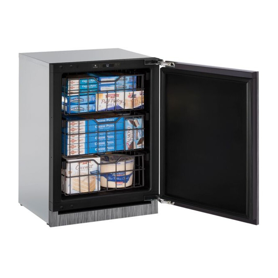
Page 36: Freezer Baskets
USER GUIDE SAFETY • INSTALLATION & INTEGRATION • OPERATING INSTRUCTIONS • MAINTENANCE • SERVICE Cleaning Freezer Baskets Baskets may be cleaned in a soapy warm water solution. A general household disinfectant, safe for plastics, may be FREEZER BASKET INSTALLATION & REMOVAL used if necessary. -
Page 37: Maintenance
USER GUIDE SAFETY • INSTALLATION & INTEGRATION • OPERATING INSTRUCTIONS • • SERVICE MAINTENANCE Cleaning Integrated Models To clean integrated panels, use household cleaner per the EXTERIOR CLEANING cabinet manufacturer’s recommendation. Stainless Models Stainless door panels and handles can discolor when INTERIOR CLEANING exposed to chlorine gas, pool chemicals, saltwater or Disconnect power to the unit. - Page 38 USER GUIDE SAFETY • INSTALLATION & INTEGRATION • OPERATING INSTRUCTIONS • • SERVICE MAINTENANCE NOTICE The drain pan was not designed to capture the water created when manually defrosting. To prevent water from overflowing the drain pan and possibly damaging water sensitive flooring, the unit must be removed from cabinetry.
-
Page 39: Cleaning Condenser
USER GUIDE SAFETY • INSTALLATION & INTEGRATION • OPERATING INSTRUCTIONS • MAINTENANCE • SERVICE Cleaning Condenser INTERVAL - EVERY SIX MONTHS To maintain operational efficiency, keep the front grille (plinth strip/base fascia) free of dust and lint, and clean the condenser when necessary. Depending on environmental conditions, more or less frequent cleaning may be necessary. -
Page 40: Extended Non-Use
If the unit will be exposed to temperatures of 40°F (5°C) or less, the steps above must be followed. For questions regarding winterization, please call U-Line at 414.354.0300. CAUTION Damage caused by freezing temperatures is not covered by the warranty. -
Page 41: Troubleshooting Guide
• Evaporator: Refrigerant flowing through an evaporator may sound like boiling liquid. BEFORE CALLING FOR SERVICE If you think your U-Line product is malfunctioning, read • Condenser Fan: Air moving through a condenser may the CONTROL OPERATION section to clearly understand be heard. -
Page 42: Checking Product Temperature
USER GUIDE SAFETY • INSTALLATION & INTEGRATION • OPERATING INSTRUCTIONS • MAINTENANCE • SERVICE Causes which affect the internal temperatures of Problem Possible Cause and Remedy the cabinet include: Product Is Not Air temperature does not indicate product • Temperature setting. Cold Enough. -
Page 43: Wire Diagram
USER GUIDE SAFETY • INSTALLATION & INTEGRATION • OPERATING INSTRUCTIONS • MAINTENANCE • SERVICE Wire Diagram Wire Diagram 1... -
Page 44: Product Liability
The part that caused the damage must be returned to U-Line in its entirety. The part must be clearly labeled with the serial number of the unit it was removed from, the date, and the servicer who removed the part. -
Page 45: Warranty Claims
• Final Billing – Remodel • Narda (or equivalent) form or submitted online at Noting all of the following on the warranty claim will be www.u-line.com considered proof of purchase, hard copy will not be required: • 60 day submittal deadline from date of completed service •... -
Page 46: Ordering Replacement Parts
Warranty parts will be shipped at no charge after U-Line confirms warranty status. Please provide the model, serial number, part number and part description. Some parts will require color or voltage information. - Page 47 Never use a torch on a fully charged refrigeration system. Never substitute U-Line OEM replacement parts or methods of construction. R-600a must be stored and transported in Technician must observe all federal, state and local laws regarding refrigerants.
- Page 48 USER GUIDE SAFETY • INSTALLATION & INTEGRATION • OPERATING INSTRUCTIONS • MAINTENANCE • SERVICE R-600A SPECIFICATIONS/LABELING WARNING R-600a equipped products are labeled (both the unit and the compressor). Only skilled and well trained service technicians permitted to service R-600a equipped products. R-600a is colorless and odorless.
-
Page 49: Leak Detection
USER GUIDE SAFETY • INSTALLATION & INTEGRATION • OPERATING INSTRUCTIONS • MAINTENANCE • SERVICE Evacuate/reclaim via the piecing pliers to ensure the When re-brazing, the system must be purged with dry system is empty of R-600a before any system work is nitrogen and at least one access point open to the performed. - Page 50 USER GUIDE SAFETY • INSTALLATION & INTEGRATION • OPERATING INSTRUCTIONS • MAINTENANCE • SERVICE The low side of the refrigeration system (evaporator, Proper ventilation during service is required. compressor and suction line) must be leak tested with the compressor off (equalized pressure). Never apply a torch to a charged R-600a refrigeration system.
-
Page 51: Refrigeration System Diagnosis Guide
USER GUIDE SAFETY • INSTALLATION & INTEGRATION • OPERATING INSTRUCTIONS • MAINTENANCE • SERVICE System Diagnosis Guide REFRIGERATION SYSTEM DIAGNOSIS GUIDE System Suction Suction Compressor Condenser Capillary Evaporator Wattage Condition Pressure Line Discharge Tube Normal Normal Slightly below Very hot Very hot Warm Cold... -
Page 52: Compressor Specifications
USER GUIDE SAFETY • INSTALLATION & INTEGRATION • OPERATING INSTRUCTIONS • MAINTENANCE • SERVICE Compressor Specifications OVERLOAD PROTECTOR STARTING RELAY DANGER Electrocution can cause death or serious injury. Burns from hot or cold surfaces can cause RELAY COVER CAPACITOR serious injury. Take precautions when servicing this unit. -
Page 53: Troubleshooting - Extended
USER GUIDE SAFETY • INSTALLATION & INTEGRATION • OPERATING INSTRUCTIONS • MAINTENANCE • SERVICE Troubleshooting - Extended MAIN CONTROL The main control board is very robust and is rarely the SPECIFIC ERRORS AND ISSUES cause of system issues. It is important to fully diagnose The technically advanced diagnostic capabilities of the the board for any suspected failures before attempting to electronic controls utilized on the 3000 series units allows... - Page 54 USER GUIDE SAFETY • INSTALLATION & INTEGRATION • OPERATING INSTRUCTIONS • MAINTENANCE • SERVICE Testing The Main Control Other Suspected Main Control Faults If other components have been ruled out as being faulty If the main control is suspected of being faulty, the but the unit continues to have operating issues, it is most following procedure should be performed to verify main likely due to a configuration error.
-
Page 55: Fault System Diagnosis Guide
USER GUIDE SAFETY • INSTALLATION & INTEGRATION • OPERATING INSTRUCTIONS • MAINTENANCE • SERVICE FAULT SYSTEM DIAGNOSIS GUIDE Error Solution 1 Solution 2 Solution 3 No Comm Inspect Customer UI and Data Cable (if defective replace entire door) Zone T Open Inspect zone thermistor Inspect main control wire harness connection. -
Page 56: Thermistor Failure
USER GUIDE SAFETY • INSTALLATION & INTEGRATION • OPERATING INSTRUCTIONS • MAINTENANCE • SERVICE REFRIGERATION SYSTEM DIAGNOSIS GUIDE System Suction Suction Line Compressor Condenser Capillary Evaporator Wattage Condition Pressure Discharge Tube Normal Normal Slightly below Very hot Very hot Warm Cold Normal room... -
Page 57: Quick Chill
USER GUIDE SAFETY • INSTALLATION & INTEGRATION • OPERATING INSTRUCTIONS • MAINTENANCE • SERVICE REED SWITCH Door Removed For Illustration Purposes A reed switch is used to monitor door state. When the door is closed magnetic force pulls the reed to its contact and closes the circuit which turns the light and display off. -
Page 58: Evaporator Fan
USER GUIDE SAFETY • INSTALLATION & INTEGRATION • OPERATING INSTRUCTIONS • MAINTENANCE • SERVICE Relay Toggle CONVECTION COOLING All 3000 series units are equipped with an advanced convection cooling system. Convection cooling stabilizes Select cabinet temperature, cools product faster and increases RETURN TO MENU energy efficiency. -
Page 59: Relay Status
USER GUIDE SAFETY • INSTALLATION & INTEGRATION • OPERATING INSTRUCTIONS • MAINTENANCE • SERVICE All Errors To access All Errors follow the steps below. Number Error ID Of Occurrences Select 1. Press to select “All Errors”. RETURN TO MENU ALL ERRORS NO COMM 0 2. -
Page 60: Interior Lighting
Down U-Select Lighting information. U-Line 3000 Series unit uses a state of the art theatre style LED lighting system. 4. Press to exit the Relay Status menu. NOTE: Lighting system is designed to fade in and out when switching states. -
Page 61: Error Notification
USER GUIDE SAFETY • INSTALLATION & INTEGRATION • OPERATING INSTRUCTIONS • MAINTENANCE • SERVICE ERROR NOTIFICATION Actual Temps The 3000 model series continuously monitors a series of Select inputs and parameters to ensure proper and efficient operation of your unit. Should the system detect a fault, an RETURN TO MENU error notification will be displayed on the user interface. - Page 62 USER GUIDE SAFETY • INSTALLATION & INTEGRATION • OPERATING INSTRUCTIONS • MAINTENANCE • SERVICE Thermistors Thermistor Resistance Data Nominal Resistance Temp (F) Temp (C) Thermistors are used for various temperature readings. (OHMS)* Thermistors provide reliable temperature readings using a 169157 resistance which varies based on surrounding 121795 temperatures.
- Page 63 USER GUIDE SAFETY • INSTALLATION & INTEGRATION • OPERATING INSTRUCTIONS • MAINTENANCE • SERVICE Defrost These units are frost free technology Model Length/ Stop Between Minutes Point Defrost Time 2218R/WC 2224BEV/R/WC 3018R/WC 1224DWR 1224WC 3024DWR/FZR/BEV/R 3036BVWC/RR/WCWC C01224F C029F 1224RF Defrost 1...
-
Page 64: Remove Fan And Cover
USER GUIDE SAFETY • INSTALLATION & INTEGRATION • OPERATING INSTRUCTIONS • MAINTENANCE • SERVICE Remove Fan and Cover Evaporator Fan Replacement Should the evaporator fan need to be replaced follow the steps below. CONVECTION COOLING This unit is equipped with an advanced convection cooling system. - Page 65 USER GUIDE SAFETY • INSTALLATION & INTEGRATION • OPERATING INSTRUCTIONS • MAINTENANCE • SERVICE 11.Grasp evaporator cover, pull the top forward and up as bottom of cover is installed behind the front edge of the drain trough. 12.While pulling the evaporator cover clear of the unit, it may be necessary to use your free hand to manipulate the fan plug end through the pass-through hole.
-
Page 66: One Year Limited Warranty
For products installed and used for normal residential use, material cosmetic defects are included in this warranty, with coverage limited to 60 days from the date of original purchase. All service provided by U-Line under the above warranty must be performed by a U-Line factory authorized servicer, unless otherwise specified by U-Line.
Need help?
Do you have a question about the U-3060FZRINT-00A and is the answer not in the manual?
Questions and answers