Table of Contents
Advertisement
Quick Links
OM−01587−01
CD
January 20, 1981
Rev. C 05-20-10
INSTALLATION, OPERATION,
AND MAINTENANCE MANUAL
WITH PARTS LIST
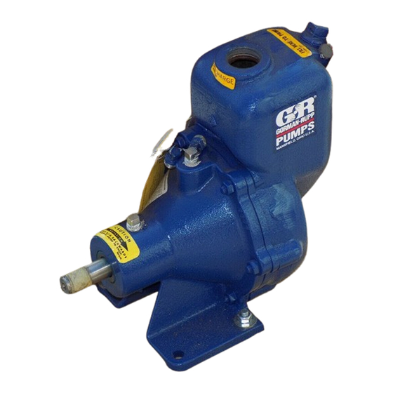
30 SERIES PUMP
MODEL
31A3−B
THE GORMAN-RUPP COMPANY D MANSFIELD, OHIO
www.grpumps.com
D
GORMAN-RUPP OF CANADA LIMITED
ST. THOMAS, ONTARIO, CANADA
Printed in U.S.A.
e
1981 The Gorman-Rupp Company
Advertisement
Table of Contents

Related Manuals for GORMAN-RUPP PUMPS 30 Series


Summary of Contents for GORMAN-RUPP PUMPS 30 Series
- Page 1 OM−01587−01 January 20, 1981 Rev. C 05-20-10 INSTALLATION, OPERATION, AND MAINTENANCE MANUAL WITH PARTS LIST 30 SERIES PUMP MODEL 31A3−B THE GORMAN-RUPP COMPANY D MANSFIELD, OHIO www.grpumps.com GORMAN-RUPP OF CANADA LIMITED ST. THOMAS, ONTARIO, CANADA Printed in U.S.A. 1981 The Gorman-Rupp Company...
- Page 2 Register your new Gorman-Rupp pump online at www.grpumps.com Valid serial number and e-mail address required. RECORD YOUR PUMP MODEL AND SERIAL NUMBER Please record your pump model and serial number in the spaces provided below. Your Gorman-Rupp distributor needs this information when you require parts or service. Pump Model: Serial Number:...
-
Page 3: Table Of Contents
TABLE OF CONTENTS INTRODUCTION ..........PAGE I −... - Page 4 TABLE OF CONTENTS (continued) TROUBLESHOOTING − SECTION D ......PAGE D − 1 PREVENTIVE MAINTENANCE .
-
Page 5: Introduction
This pump is a 30 Series, enclosed impeller, self- priming centrifugal model without a suction check valve. The pump is designed to handle petroleum... -
Page 6: Safety - Section A
30 SERIES OM−01587 SAFETY - SECTION A This information applies to 30 Series ba- sic pumps. Gorman-Rupp has no con- trol over or particular knowledge of the power source which will be used. Refer This pump is designed to handle most... - Page 7 OM−01587 30 SERIES to a boil, build pressure, and cause the pump casing to rupture or explode. Do not remove plates, covers, gauges, pipe plugs, or fittings from an over- heated pump. Vapor pressure within the Overheated pumps can cause severe pump can cause parts being disen- burns and injuries.
-
Page 8: Installation − Section Bpage B
30 SERIES OM−01587 INSTALLATION − SECTION B Review all SAFETY in Section A. specific application. Since the pressure supplied to the pump is critical to performance and safety, Since pump installations are seldom identical, this be sure to limit the incoming pressure to 50% of the... -
Page 9: Positioning Pump
OM−01587 30 SERIES c. Carefully read all tags, decals, and markings use lifting equipment with appropriate capacity. on the pump assembly, and perform all duties Drain the pump and remove all customer-installed indicated. equipment such as suction and discharge hoses or piping before attempting to lift existing, installed units. -
Page 10: Connections To Pump
30 SERIES OM−01587 Connections to Pump strainer furnished with the pump will also pass through the pump itself. Before tightening a connecting flange, align it ex- If a strainer is not furnished with the pump, but is actly with the pump port. Never pull a pipe line into... -
Page 11: Discharge Lines
OM−01587 30 SERIES recommended minimum submergence vs. veloc- by installing a standard pipe increaser fitting at the ity. end of the suction line. The larger opening size will reduce the inlet velocity. Calculate the required submergence using the following formula based NOTE on the increased opening size (area or diameter). -
Page 12: Alignment
30 SERIES OM−01587 vent clogging, but not so large as to affect pump Align spider insert type couplings by using calipers discharge capacity. to measure the dimensions on the circumference of the outer ends of the coupling hub every 90_. -
Page 13: Drive Belt Tensioning
OM−01587 30 SERIES systems using two or more belts, make certain that the belts are a matched set; unmatched sets will cause accelerated belt wear. Do not operate the pump without the shields and/or guards in place over the drive shaft, belts, and/or couplings, or other rotating parts. -
Page 14: Operation − Section C
OM−01587 30 SERIES OPERATION − SECTION C Review all SAFETY information in Section A. Add liquid to the pump casing when: 1. The pump is being put into service for the Follow the instructions on all tags, labels and first time. -
Page 15: Operation
OM−01587 30 SERIES If rotation is incorrect on a three-phase motor, have Liquid Temperature And Overheating a qualified electrician interchange any two of the The maximum liquid temperature for this pump is three phase wires to change direction. If rotation is 160_ F (71_C). -
Page 16: Stopping
OM−01587 30 SERIES not, check for air leaks in the seal, gasket, or dis- normal for bearings, and they can operate safely to charge valve. at least 180_F (82_C). Checking bearing temperatures by hand is inaccu- Open the suction line, and read the vacuum gauge rate. -
Page 17: Troubleshooting − Section D
30 SERIES OM−01587 TROUBLESHOOTING − SECTION D Review all SAFETY information in Section A. Before attempting to open or service the pump: 1. Familiarize yourself with this manual. 2. Lock out or disconnect the power source to ensure that the pump will remain inoperative. - Page 18 OM−01587 30 SERIES TROUBLE POSSIBLE CAUSE PROBABLE REMEDY Suction intake not submerged at Check installation and correct PUMP STOPS OR FAILS TO DELIVER proper level or sump too small. submergence as needed. RATED FLOW OR Replace worn or damaged parts.
-
Page 19: Preventive Maintenance Page D
30 SERIES OM−01587 equipped) between regularly scheduled inspec- PREVENTIVE MAINTENANCE tions can indicate problems that can be corrected Since pump applications are seldom identical, and before system damage or catastrophic failure oc- pump wear is directly affected by such things as curs. -
Page 20: Pump Maintenance And Repair - Section Epage E
OM−01587 30 SERIES PUMP MAINTENANCE AND REPAIR − SECTION E MAINTENANCE AND REPAIR OF THE WEARING PARTS OF THE PUMP WILL MAINTAIN PEAK OPERATING PERFORMANCE. STANDARD PERFORMANCE FOR PUMP MODEL 31A3−B Based on 70_ F (21 _ C) clear water at sea level with minimum suction lift. - Page 21 OM−01587 30 SERIES SECTION DRAWING PARTS PAGE Figure 1. Pump Model 31A3−B PAGE E − 2 MAINTENANCE & REPAIR...
-
Page 22: Parts List
OM−01587 30 SERIES PARTS LIST Pump Model 31A3−B (From S/N 263375 Up) If your pump serial number is followed by an N", your pump is NOT a standard production model. Contact the Gorman-Rupp Company to verify part numbers. ITEM PART MAT’L... -
Page 23: Pump And Seal Disassembly And Reassembly
OM−01587 30 SERIES PUMP AND SEAL DISASSEMBLY 3. Allow the pump to completely cool if overheated. AND REASSEMBLY 4. Check the temperature before opening any covers, plates, or Review all SAFETY information in Section A. plugs. 5. Close the suction and discharge Follow the instructions on all tags, label and de- valves. -
Page 24: Impeller Removal
30 SERIES OM−01587 Impeller Removal If no further disassembly is required, see Seal Reassembly and Installation. Immobilize the impeller by wedging a brass rod be- tween the vanes. Shaft And Bearing Removal And Disassembly Install the shaft key (16). Install a lathe dog on the When the pump is properly operated and main- drive end of the shaft (18) with the V"... -
Page 25: Shaft And Bearing Reassembly And Installation
OM−01587 30 SERIES be replaced any time the shaft and bear- ings are removed. Clean the bearing housing, shaft and all compo- nent parts (except the bearings) with a soft cloth To prevent damage during removal from soaked in cleaning solvent. Inspect the parts for the shaft, it is recommended that bearings wear or damage and replace as necessary. -
Page 26: Seal Installation
30 SERIES OM−01587 Most cleaning solvents are toxic and When installing the shaft and bearings into flammable. Use them only in a well-ven- the bearing bore, push against the outer tilated area free from excessive heat, race. Never hit the balls or ball cage. -
Page 27: Impeller Installation
OM−01587 30 SERIES RETAINER ROTATING BELLOWS ELEMENT SEAL PLATE IMPELLER IMPELLER SHAFT STATIONARY ELEMENT SPRING STATIONARY SEAT Figure 3. Seal Assembly (2) onto the shaft until fully seated against the shaft shoulder, then measure the distance between the back of the impeller and the seal plate. This clear- ance should be between .085 and .111 inch (2,2... -
Page 28: Final Pump Assembly
30 SERIES OM−01587 placement wear ring into the pump casing (1) until For maximum pump efficiency, the impeller should fully seated in the casing bore. be centered within the pump casing. To verify the impeller positioning, measure the pump casing and impeller as shown in Figure 4. -
Page 29: Bearings
OM−01587 30 SERIES Bearings The pedestal was fully lubricated when shipped from the factory. Monitor the condition of the bearing lubri- There are no provisions in the pedestal for check- cant for evidence of rust or moisture con- ing the oil level, therefore it is recommended that densation. - Page 30 For U.S. and International Warranty Information, Please Visit www.grpumps.com/warranty or call: U.S.: 419−755−1280 International: +1−419−755−1352 For Canadian Warranty Information, Please Visit www.grcanada.com/warranty or call: 519−631−2870 THE GORMAN-RUPP COMPANY D MANSFIELD, OHIO GORMAN-RUPP OF CANADA LIMITED ST. THOMAS, ONTARIO, CANADA...
Need help?
Do you have a question about the 30 Series and is the answer not in the manual?
Questions and answers